Development of Particle-in-Cell Simulation in a Two Dimensional Trench Geometry
Abstract
A two dimensional electrostatic Particle-in-Cell simulation code is developed to investigate anisotropy of ions in a trench geometry for plasma etching. The numerical simulation results suggest that if the trench width is larger than Debye length scale, anisotropy can be lost due to potential development across the trench. Furthermore, the effects of ion charge build up on the trench bottom is investigated, which can degrade the anisotropy.
Index Terms:
Plasma-material surface interaction, Particle-in-Cell simulation, Trench geometry, Anisotropic etching.I Introduction
For semiconductor processing in industries, plasma etching has been one of the key technologies. We can categorize the material etching into two types: dry etching and wet etching [1]. Wet etching employs chemical reactions by liquid to etch materials, which is a relatively low cost process. However, when the trench size becomes small, it may cause undercut [2] because etching direction becomes isotropic (meaning the etching is uniform in all directions). On the other hand, dry etching employs charged gases to etch materials. Ion bombardment resulting from acceleration by sheath potential is the primary mechanism for dry etching. By the dry etching, anisotropic etching can be achieved because the ion bombardment is primarily in one direction.
A capacitively coupled plasma (CCP) [3, 4] is frequently employed for plasma etching. A CCP can be seen as a plasma bounded by two plates. One plate with an etching target is connected to the radio frequency (RF) bias and the other is grounded. Plasma discharge is sustained by stochastic heating in the sheath [5]. When the plasma is generated, a sheath is developed near the material surface. The sheath accelerates ions and reflects electrons. Sheath formation is the key mechanism for anisotropic ion bombardment. On the other hand, within the trench, we do not want sheath to be developed in the direction perpendicular to the trench. Otherwise, the ions accelerated by the wall can erode sidewalls of the trench. In this work, the plasma behavior in the trench geometry is investigated by varying its size. We demonstrate that the trench width need to be smaller than a few Debye length.
The industrial trend shows that the etching scale is becoming smaller and smaller to reduce computational power [6], and improve memory size. To resolve sub-micron scale, one may need to rely on molecular dynamics approach which can be numerically demanding, however. In this work, despite the scale is slightly larger (than the sub-micron scale), we would like to establish a firm ground of self-consistent charged particle dynamics in a trench geometry; whether ion anisotropy is kept or not. Despite seemingly straightforward, Particle-in-Cell (PIC) simulation [7, 8] in a realistic two-dimensional trench geometry is not conducted by many authors [9]. We consider the plasma discharge based on industrial setting between two plates as in a capacitively coupled plasma and investigate the stable discharge for etching process in the trench geometry.
This paper is organized as follows. In Section II, the basic computational model in the presence of kinetic ions and the electrons is described. In Section III, a series of two dimensional Particle-in-Cell simulation, that are in a square geometry, in a periodic square geometry, and finally with the trench geometry, are discussed. We summarize this work in Section IV.
II Computational model
In this section, our computational model of two dimensional electrostatic PIC simulation is described. In the numerical simulation we incorporate both the electron and an ion species. We extend our previous work in [10] from one dimension to two dimension.
In this paper, we denote as the background plasma density and () as the electron (ion) temperature. We denote and as the mass and the charge of the species ( for electrons and for ions), and as the unit charge. The Debye length is given by and the plasma frequency is given by , where is the vacuum permittivity. We employ the MKS unit in this paper. As in [10], after normalizing length by Debye length, time by the inverse of plasma frequency [11], and the electrostatic potential by , the equations of motion are given by
| (1) |
| (2) |
| (3) |
and
| (4) |
where for and for . Here, and represent the coordinates of the configuration space and the velocity space, respectively. The normalized time variable is given by . As a reminder the velocities are normalized by the electron thermal velocity .
On the other hand, normalized two dimensional Poisson equation is given by (we normalize densities by )
| (5) |
In (1)-(5), all the quantities with “bar” denote normalized ones. Here, and while is the electrostatic potential. For the numerical derivative, we take Euler differencing using two mesh points at the boundaries (central differencing taken, otherwise).
In numerically integrating (1)-(4), we employ the leapfrog method [8, 12]. Because and dynamics are independent, we evolve in the order of (1) and (2), (5), (3) and (4). In solving two dimensional Poisson equation (5), we employ a Gauss-Seidel method and a Jacobi method. This is to assure correctness of the solution in the complicated trench geometries first, despite it may not be one of the fastest numerical schemes. We employ a homogeneous Dirichlet boundary condition for the electrostatic potential at one of the electrodes and a time dependent (an RF like) Dirichlet boundary condition at the other electrode.
III Two dimensional simulation results
In this section, we discuss our numerical simulation results by our newly developed two dimensional PIC code. To reach our final goal of simulating a realistic trench geometry, we build our models by verifying from a simple square geometry. We then impose periodic condition in the direction parallel to the plates (which we refer to as direction), and finally incorporate a trench geometry.
Plasma parameters employed in the numerical simulation are: plasma temperature (the temperature ratio ) and a mass ratio of . For example, with and , we obtain and . Then the industrial RF frequency typically used for capacitively coupled plasmas, , reads in our normalized units. All the plasma dynamics in this work is regarded as collisionless.
III-A PIC simulation in a square geometry
We first build a PIC model for a simple square geometry shown in Fig. 1. In initiating the PIC simulation, we employ Gaussian for the velocity distribution for both and (see [10] for methods to produce Gaussian):
| (6) |
where for electrons ( for the ions) and is the ion thermal velocity.
The initial particle positions in the configuration space are uniform within and . We distribute particles using a random number generator. In Fig. 1, we take and . The number of mesh points we take here are and (the mesh size is the Debye length). We employ Dirichlet boundary condition on , , , and (we set assuming the four boundaries are grounded). Note that the electric field components along the surface of the plates are taken to be zero (we assume conducting walls). We take one hundred particles per two-dimensional-cell for both the ions and the electrons. The time step is given by .
Sheath potential is developed [10] as shown in Fig. 1(a) and electrons are confined in two-dimensional square domain. As shown in Fig. 1(b), high energy electrons are lost into the boundaries making the plasma positively charged at the steady state. To reach Fig. 1(a) and Fig. 1(b), (1) to (5) are time advanced self-consistently up to . Ions are accelerated at the sheath due to large electric field toward the boundaries satisfying the Bohm-sheath criterion (as in [10]) . In sustaining a steady state plasma discharge, if an ion is lost at the boundaries, we provide the bulk plasma with a thermal ion regarding it as an ionization of the ambient neutral gas. In Fig. 1(b), four percent of total electrons are plotted.
Single electron orbit in a square geometry is shown in Fig.1(c). As an unexpected by-product of the sheath dynamics study, we discover the orbit fill in the space uniformly. This, as we observe, is similar to billiard balls reflecting at the elastic walls and filling in the volume ergodically [13] (note that the electrons’ reflection is given by deceleration and acceleration by the electric field near the boundaries).


III-B PIC simulation with periodicity and an RF bias
To further move on, we make the direction periodic. This is a second step toward the trench geometry. This implies that the trench pattern repeats in the direction and the trench region we study are far away from the capacitor edges. The parameters taken in Fig.2 is the same with Fig.1 except that and the Poisson equation is solved by imposing periodicity at and . When the particles cross , they are designed to re-enter and vice versa. We still employ Dirichlet boundary conditions at () and [ for an RF biased side. We take and ]. Note that (since there are no obstacles so far, such as a trench) the plasma dynamics should be equivalent to that of one dimensional system.
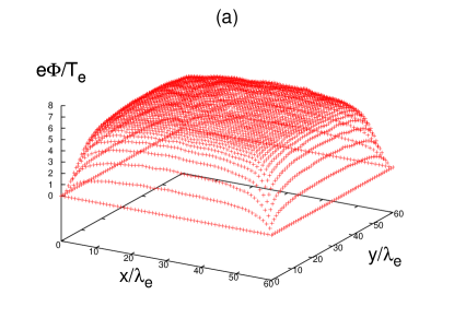
A surface plot of the electrostatic potential is shown in Fig. 2(a). A comparison with one dimensional simulation results are given in Fig. 2(b) and Fig. 2(c). Figure 2(b) compares variation of ( is the direction perpendicular to the plates, as a reminder) at fixed times and , and Fig. 2(c) compares the time dependence of potential values at . In Fig. 2(c), long time scale oscillation is by the bounce motion induced by the RF boundary condition and small ripples originate from plasma oscillations. The two data sets from one dimensional and two dimensional simulation compare favorably.
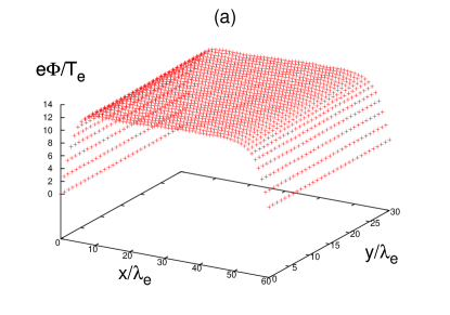
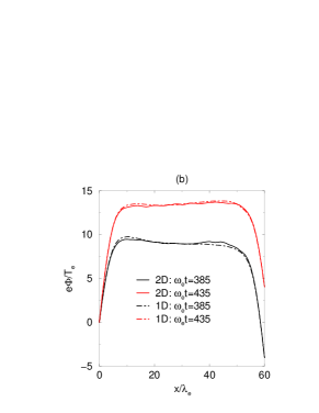
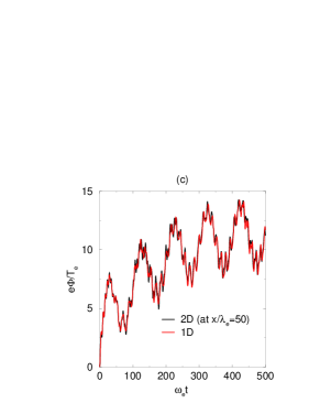
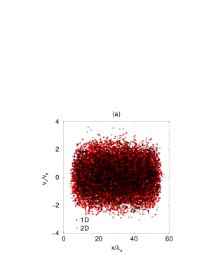
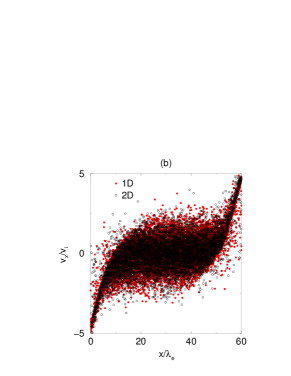
Figure 3(a) compares the electron phase space plots of a two dimensional PIC simulation with all the information projected onto (black hollow dots), with plots from a one dimensional PIC simulation (red dots), both at . At the steady state of the RF biased discharge, the electrons are absent in the sheath regions. Likewise, Fig. 3(b) is from ion phase space plots at , which demonstrates ions’ rapid acceleration toward the boundaries.
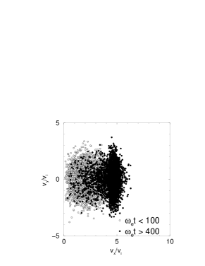
Interestingly, we can already reveal the ions’ velocity anisotropy for those reaching the plate on the right (employing the results shown in Figs.2 and 3). The two dimensional velocity distribution of ions which have reached the right boundary, , is plotted in Fig.4. In the initial phase, before the sheath is formed (the hollow black dots in Fig.4 is from ), the ion velocities are rather isotropic. After the sheath formation (black solid dots in Fig.4 obtained within ), when the ions are accelerated toward the plate, we see an enhanced anisotropy with the component being dominant.
III-C PIC simulation with a trench geometry
Finally, we incorporate the trench geometry. The size of the plasma is same as in III-B with an additional trench length of given in the direction (see Figs. 5 and 6). The trench width in the direction is given by in Fig. 5, and in Fig. 6, respectively. In Figs. 5 and 6, the bulk region given by is the periodic region as in III-B. Note that we recycle the ions hitting the walls as before, but the ionization is assumed only in the bulk region.
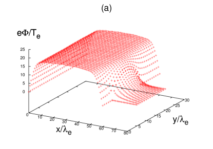
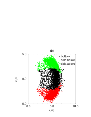
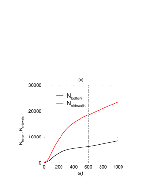
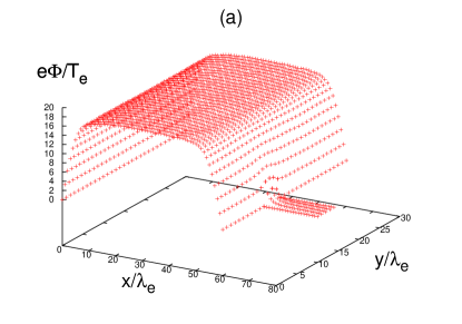
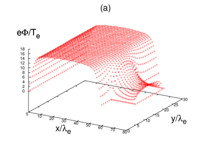
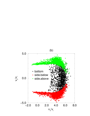
In Fig.5, a potential profile is developed in the direction. This is because the trench width is much larger than the Debye length. Finite potential height within the trench can be observed in Fig.5(a). The component of the electric field in the trench causes ions to be accelerated toward the sidewalls (which is not preferred from a plasma etching point of view). In Fig. 5(b), velocity distributions of the ions which have reached (hit) the trench bottom (at and , black dots), the lower side wall (at and , red dots), and the upper side wall (at and , green dots) are plotted. The velocity data are taken during the period of .
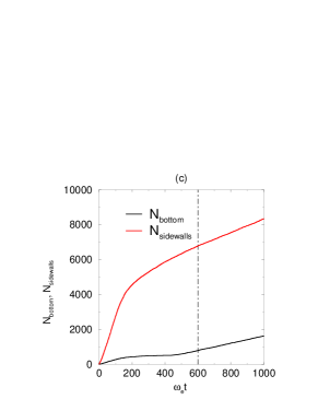
Accumulated numbers of particles reaching the bottom () and the two sidewalls () are shown in Fig.5(c). During the period , when we have constant ion fluxes toward the trench surface (meaning and are constant), ions reach the bottom and ions reach the sidewalls (the ratio between them are ).
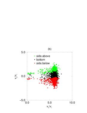
A similar analysis is done for a relatively small trench width of in Fig. 6. The trench bottom is located at and . In a thin trench region, potential profile is ignorable [see Fig.6(a)]. Ions can directly bombard the bottom of the trench. Velocity distributions of the ions at the boundaries are given in Fig. 6(b), and accumulated numbers of particles are given in Fig. 6(c). The velocity anisotropy in Fig. 6(b) is much clear compared to Fig. 5(b). During the period (as in Fig.5), ions reach the bottom and ions reach the sidewalls (the ratio between them are ). By comparing Fig.5 and Fig.6, what we learn is that the control of the anisotropy can be related to the competition of sheath dynamics between two perpendicular directions which are ”” (direction toward the plates) and ”” (direction across the trench).
III-D Charge build up effects
As we discussed in I, we are also interested in the effect of charge build-ups on the trench surface [2]. If ions keep hitting the trench region, it is possible that the trench bottom become positively charged and thus the potential can rise. The potential at the bottom of trench can be positive (relative to the trench region). Then some of the ions are repelled which in turn can gives rise to the sidewall erosion. Here, on top of the analysis in Fig.5, we provide the plasma with additional stationary ion charge density at the trench bottom. We provide an extra test ion density of at and (we do not time advance this latter portion of the ion density).
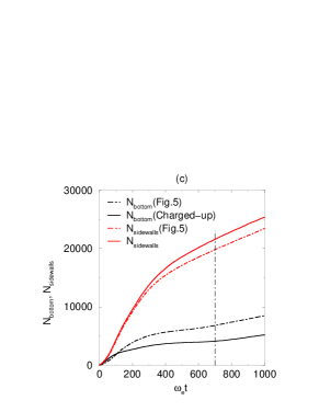
Figure 7(a) shows potential profile at which demonstrates significant potential variation in the trench region compared to the previous two cases. The potential gradient cause electric field to decelerate ions which was originally approaching the trench bottom. As in Fig. 5, velocity distributions are given in Fig. 7(b), which suggest loss of anisotropy [see Fig. 5(b) as well]. The accumulated numbers of particles are given in Fig. 7(c): the solid curves are the ones with charged build-ups and the dashed curves are the ones from Fig. 5(c) for comparison. The test simulation result shows much less ions are reaching the bottom but instead more ions are reaching the sidewalls. During the period of , ions reach the bottom and ions reach the sidewalls (the ratio between them are . As a reminder, smaller ratios suggest better anisotropy).
IV Summary and discussions
In this work, we have built a two-dimensional electrostatic PIC model to examine anisotropy of ion bombardment in a trench geometry [2]. We made our simulation results gradually closer to realistic plasma discharge processes. We have started from a two dimensional square shape with Dirichlet boundary conditions, then advanced to a square geometry with a periodic boundary condition, and finally added the trench geometry. The simulation results indicate ions can drift toward the sidewalls when the potential profile is developed in the trench region when the width is larger than a few Debye length. To the contrary, anisotropy can be achieved in a relatively small trench size. Furthermore, positive charging up on the trench bottom has been examined. The numerical simulation result indicates that if we have positive potential due to ions’ accumulation on the trench bottom, we can lose anisotropy.
To focus on the basic geometrical effects of the trench in the first place, the trench size we dealt in this work are larger than conventional ones (while our bulk plasma size is comparable to the industrial processing plasmas). In the future, we would like to extend our two dimensional PIC simulation to a sub-micron trench with a further speed-up of the numerical computation, the field solver in particular [14]. On the other hand, another path is to develop an N-body simulation method (as in gravitational N-body problems [15]) by calculating individual Coulomb force between charged particles.
Generally, secondary electron emission is not a preferable ingredient for etching. It causes the sheath instability and enhance power loss [16, 17, 18, 19]. However, in the trench region, it is possible that the secondary electron emissions reduce the plasma potential. Ions affected by sidewalls can be reduced. Inclusion of the secondary electron emission effects into our two dimensional model through the ion bombardment [16] and the electron bombardment [17, 10] is yet our another near future task.
Acknowledgment
The authors would like to thank Dr. M. R. Smith and Dr. F. C. N. Hong of National Cheng Kung University, and Dr. I. Kaganovich of Princeton University for useful discussions. This work is supported by Taiwan MOST 103-2112-M-006-007 and MOST 104-2112-M-006-019.
References
- [1] M. A. Lieberman and A. J. Lichtenberg, Principles of Plasma Discharges and Materials Processing, 2nd ed. Hoboken, NJ, USA: John Wiley and Sons, 2005, pp. 1-22.
- [2] W. N. G. Hitchon, Plasma Processes for Semiconductor Fabrication, Cambridge, UK:Cambridge University Press, 1999, pp. 121-141.
- [3] V. A. Godyak and R. B. Piejak, “Abnormally low electron energy and heating-mode transition in a low-pressure argon rf discharge at 13.56 MHz,” Physical Review Letters, vol. 65, no. 8, pp. 996-999, Aug. 1990.
- [4] M. M. Turner, “Pressure Heating of Electrons in Capacitively Coupled rf Discharges,” Physical Review Letters, vol. 75, no. 7, pp. 1312-1315, Sep. 1995.
- [5] V. A. Godyak and R. B. Piejak, “Dynamic model of the electrode sheaths in symmetrically driven rf discharges,” Physical Review A, vol. 42, no. 4, pp. 2299-2312, Aug. 1990.
- [6] M. R. Smith, private communication, 2016.
- [7] J. Dawson, “One dimensional plasma model,” Physics of Fluids, vol. 5, no. 4, pp. 445-459, Apr. 1962.
- [8] C. K. Birdsall and A. B. Langdon, Plasma Physics via Computer Simulation, IOP publishing, 1986, p. 12.
- [9] Z. Dai, G. Yue, and Y. Wang, “Simulations of Ion Behaviors in a Photoresist Trench During Plasma Etching Driven by a Radio-Frequency Source,” Plasma Science and Technology, vol. 14, no. 3, pp. 240-244, Mar. 2012.
- [10] C. W. Huang, Y. C. Chen, and Y. Nishimura, “Particle-in-Cell Simulation of Plasma Sheath Dynamics With Kinetic Ions,” IEEE Transactions on Plasma Science, vol. 43, no. 2, pp. 675-682, Feb. 2015.
- [11] D. R. Nicholson, Introduction to Plasma Theory, 2nd ed. Melbourne, FL, USA:Krieger Publishing, 1992, pp. 1-7.
- [12] R. D. Ruth, “A canonical integration technique,” IEEE Transactions on Nuclear Science, vol. 30, no. 4, pp. 2669-2671, Aug. 1983.
- [13] Charged particle’s mixing with a stadium shape boundary can be investigated. See for example: H. J. Stöckmann, Quantum Chaos: An Introduction, Cambridge, UK: Cambridge University Press, 1999, pp. 14-26.
- [14] Y. Nishimura, Z. Lin, J. L. V. Lewandowski, and S. Ethier ”A finite element Poisson solver for gyrokinetic particle simulations in a global field aligned mesh,” Journal of Computational Physics, vol. 214, no. 2, pp. 657-671, May 2006.
- [15] J. Makino and M. Taiji, Scientific Simulations with Special Purpose Computers: The GRAPE Systems, Chichester, UK: John Wiley and Sons, 1998, pp. 95-103.
- [16] M. Surendra and D. B. Graves, “Particle simulations of radio-frequency glow discharges”, IEEE Transactions on Plasma Science, vol. 19, no. 2, pp. 144-157, Apr. 1991.
- [17] M. D. Campanell, A. V. Khrabrov, and I. D. Kaganovich, “General Cause of Sheath Instability Identified for Low Collisionality Plasmas in Devices with Secondary Electron Emission,” Physical Review Letters, vol. 108, no. 23, pp. 235001-1-235001-5, Jun. 2012.
- [18] M. D. Campanell, A. V. Khrabrov, and I. D. Kaganovich, “Absence of Debye Sheaths due to Secondary Electron Emission,” Physical Review Letters, vol. 108, no. 25, pp. 255001-1-255001-5, Jun. 2012.
- [19] M. D. Campanell and M. V. Umansky, “Strongly Emitting Surfaces Unable to Float below Plasma Potential,” Physical Review Letters, vol. 116, pp. 085003-1-085003-5, Feb. 2016.
| Tai-Lu Lin has completed M.S. degree at the Institute of Space and Plasma Sciences (ISAPS), National Cheng Kung University (NCKU), Tainan, Taiwan in February 2016. His thesis has focused on plasma kinetic theory in industrial plasmas. He is now with Chunghwa Picture Tubes, LTD. in Taoyuan, Taiwan. Yasutaro Nishimura received the Ph.D. degree from the University of Wisconsin-Madison, Madison, in 1998. He has worked with the Max-Planck-Institut für Plasmaphysik, Garching, Germany, and the University of California. He is currently an Associate Professor with the ISAPS, NCKU, Tainan, Taiwan, where he focuses on kinetic instabilities in high temperature magnetized plasmas. |