An Inter-Node Interference Suppression Approach in Full-Duplex Wireless Communications
Abstract
Considering that a full-duplex network is comprised of a full-duplex (FD) base station (BS) and two half-duplex (HD) users, one user transmits on the uplink channel and the other receives through the downlink channel on the same frequency. The uplink user will generate inter-user interference (IUI) on the downlink user through the interference channel. In this paper, we propose a novel IUI suppression approach when the BS knows the full channel station information. The main idea of the approach is to retransmit the weighted uplink signal as soon as it has been received at the BS. For the narrowband case, we first derive the closed-form expression of the optimum weighted coefficient when the SI is perfectly cancelled at the BS and then analyze the performance of the proposed IUI suppression approach in practical considerations. Furthermore, the proposed IUI suppression approach can be extended to the broadband case using a time-domain weighted filter. Simulation results shows the advantage over existing IUI suppression schemes.
Index Terms:
Full-duplex, inter-user interference suppression, imperfect channel information, achievable rate, energy efficiency.I Introduction
Full-duplex (FD) wireless communications simultaneously operate over the same frequency channel which have the potential to double the spectrum efficiency [1, 2, 3, 4]. The FD communications are in contrast to the half-duplex (HD) communications, which are either time-division, frequency-division, or code-division for transmitting and receiving. The main obstacle in implementing the FD transceiver is the large self-interference (SI) leaking from the local transmitter because of the closeness of the transmitter and receiver chains. Typically, the SI signal is million times stronger than the intended signal on the air. Recently, many studies have implemented the FD communication systems using combing SI suppression techniques such as passive suppression, analog suppression and digital suppression and thus the SI can be attenuated to detect the intended signal [5, 6, 7, 8, 9, 10, 11, 12]. The feasibility of FD creates new design opportunities for wireless communications. Since the SI suppression techniques are too complex for mobile users compared with the base station (BS) to implement in near future, we focus on studying a network comprising the HD mobile users and the FD BSs.
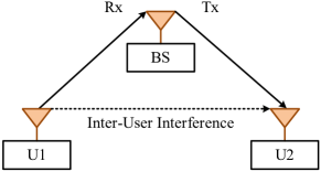
Considering about a FD network shown in Fig. 1, two HD mobile users communicate with a FD BS that supports one uplink and one downlink traffics at the same time on the same frequency. In this network, there are two types of interference: SI at the FD BS, and inter-user interference (IUI) from the uplink mobile user U1 to the downlink mobile user U2. The distinction of these two types of interferences is that, the SI signal is known at the BS receiver, because the transmitter and receiver are deployed at the same location, but the IUI is not known at the node U2. In this paper, we assume that the SI at the BS has been suppressed under the noise floor and can be neglected, and thus focus on IUI suppression. Note that SI may be easily processed [2, 1, 3, 5, 6, 7, 4, 8, 9, 10, 13, 12] as the SI information is locally available at the FD BS. However, handling IUI is much more challenging as it is between distributed users, who cannot share data information without sacrificing bandwidth resources. Roughly, IUI management techniques can be sorted into three categories as follows
1) Resource allocation techniques: To reduce IUI, Goyal et al. propose a scheduling approach to maximize the achievable rate that can be harvested from in-band FD transmissions [14, 15]. Ramirez et al. propose a joint algorithm to realize power allocation and routing considering both SI and IUI among neighboring nodes in FD wireless relay networks [16]. The authors [17] investigate IUI problem that occurs in multi-user scenarios and show that FD transmission can be made more robust against IUI, which inevitably occurs in cellular communication systems. Shao et al. [18] propose partitioning method that the cell is divided into several partitions where the IUI is regarded as Gaussian noise at the mobile user receiver and the same frequency resource is assigned to the two users who are far enough from each other. This method is suitable for the larger cell. In [19], the authors investigate the joint issue of subcarrier assignment and power allocation to maximize the sum achievable rate performance in FD orthogonal frequency division multiple access (OFDMA) networks. In [20] an IUI coordination approach based on geographical context information is given, which exploits the signal attenuation from obstacles between mobile users so that IUI is minimized. To potentially cancel co-channel interference caused by other users, the opportunistic interference suppression (OIC) technique is applied at user side and a joint mode selection, user scheduling, and channel allocation problem is formulated to maximize the system throughput [21].
2) Medium access control (MAC) techniques: The simplest method avoids IUI by picking nodes that are completely hidden from each other [22]. Singh et al. propose a distributed MAC protocol with a selection scheme for a secondary receiver [23]. The selection approach allocates different weight values to candidates for the secondary receiver. If a candidate node experiences more successful transmissions, it has a higher weight value and thus a greater chance to be selected as the secondary receiver. Another method [24] optimizes user pairing by considering IUI based on the information about IUI and traffic demands reported from all pairs of users. Goyal et al. in [25] develop a centralized MAC protocol considering interference between two users due to their concurrent transmissions. In [26], Choi et al. studies a random-access MAC protocol using distributed power control to manage IUI in wireless networks with FD BSs that serve HD users. In practice, it would be favorable to design an adaptable MAC protocol configured by specific channel and network conditions. Chen et al. [27] present a distributed FD MAC protocol that allows a BS to adaptively switch between FD and HD modes so as to reduce the influence of the IUI.
3) Physic layer (PHY) techniques: Bai et al. [28, 29] present the sum achievable rate of a three-node wireless network with a FD BS and two HD terminals. Their method is the first study to access the direct mitigation of IUI among HD terminals and the authors utilize an additional side-channel to manage IUI. To investigate the performance of the proposed approach, four schemes are proposed under different side-channel information. To combat the severe IUI in the FD communication systems, Sahai et al. [30] propose new interference management strategies which allow the network to handle IUI while obtaining rate gains by operating in-band FD transmission. In their following work, Sahai et al. propose an interference management (IA) scheme to handle IUI for multiple antennas FD communication systems so as to achieve rate gains over conventional cellular systems in terms of degrees of freedom (DoF) [31]. Using the cascade interference suppression, IUI can be effectively eliminated among multiple nodes. In [32], successive interference suppression (SIC) is applied, which is based on the fact that the downlink mobile user observes a MAC of two users and thus the downlink user has an opportunity to remove the IUI according to the transmission rates and its received powers. In their following work [33], superposition coding based IUI suppression (SCIIC) referenced by the interference suppression method applied in the X-interference channel is proposed. Mai et al. [34] manage the IUI through transmit beamforming in millimeter wave FD systems when the BS adopts multiple antenna.
In the following, we study how to reduce the IUI. If the BS knows the full channel information of the uplink, the downlink, and the interference channels, the BS knows the IUI as soon as it receives the uplink signal and thus IUI can be suppressed by transmitting the reversed signal of IUI at the BS. This idea is simple. For example, we assume the values of the uplink, the downlink, and the interference channels are s and the uplink signal is . When signal-to-noise (SNR) is high and noise can be neglected, the IUI signal is and the IUI signal can be perfectly suppressed if the BS transmits a superposition signal . This scheme does not need complex algorithm and only need some extra transmit power at the BS. Our contributions are summarized as follows: 1), first, we propose a BS assisting IUI suppression scheme and give the closed-form expression for narrowband system when the SI is perfectly cancelled at the BS; 2), second, the performance of the proposed IUI suppression scheme is furthermore evaluated under practical considerations such as imperfect SI mitigation at the base station, imperfect channel information, delay difference between the IUI and the IUI suppression signals, power control and limited total transmit power; 3), third, besides the newest IUI suppression scheme, we compared the performance of the proposed IUI suppression scheme with the HD mode, the ideal FD mode without IUI, and the FD mode with IUI but not suppressed; 4), finally, we extend the proposed approach to the broadband case.
The remainder of this paper is organized as follows. In Section II, the proposed IUI suppression scheme is given. The performance of the proposed scheme for narrowband system is introduced in Section III. Section IV extends the proposed scheme to the broadband system. Section V presents the conclusion.
Notation: denotes the expectation operation, ∗ denotes the complex conjugate, and denotes circularly symmetric Gaussian random variable with mean and variance.
II Proposed IUI suppression scheme
In this section, we will introduce the system model to be used for the remainder of the paper. As is shown in Fig. 2, the network is comprised of interference-free uplink transmission and the downlink transmission interfered by the uplink user.
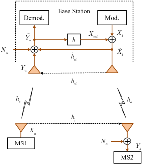
If the channels are fading, the signal model considered here is frequency-flat and block-fading. This implies that the system uses orthogonal frequency division multiplexing (OFDM) for broadband transmission over multipath channels. Thus, the signal model here represents a single narrowband subcarrier. The following equations give the signal relationship between BS and mobile users
| (1) |
where and represent the uplink and the downlink signals respectively, and and . Let and be independently and identically distributed (i.i.d.) complete white Gaussian noise with zero mean and variance of . denotes the direct link channel from the mobile user U1 to the BS, denotes the direct link channel from the BS to the mobile user U2, and denotes the interference link channel from mobile user U1 to mobile user U2. We assume that BS has the full channel station information of all other nodes. To simplify the notation, let , , and .
The in (II) can be obtained by the following recursive equation
| (2) |
For the wideband system, it is hard to solve the (2) because of the recursion of the . However, for the narrowband system, the channels can be modeled as single-path and the delay of the signal can be neglected and can be expressed as follows
| (3) |
Thus, the received signals at the BS and the donwlink user can be written as
| (4) |
We assume the uplink signal , the downlink signal , and complex Gaussian noise and are uncorrelated. Therefore, the signal-to-interference-plus-noise-ratios (SINRs) at the BS and the mobile user 2 can be expressed as
and
respectively.
Therefore, the achievable rates of the downlink and the uplink can be written as
and
respectively. Our optimization is to maximize the sum achievable rate as follows
| (5) |
In the following section, we will propose a novel IUI suppression scheme for the narrowband system.For wideband system, we will introduce the scheme in Section IV based on the narrowband system.
Moreover, we introduce the Jensen inequality [35], which will used throughout this paper, as follows
| (6) |
where is a nonnegative random variable.
III IUI Suppression Scheme for narrowband system
Since the joint optimization of the uplink transmit power , the downlink transmit power , and the IUI suppression coefficient under imperfect SI suppression at the BS cannot be derived by the explicit expression, we give the solution for different cases.
III-A Optimization for Ideal Case
We assume that the SI at the BS is perfectly suppressed, the transmit power at the uplink user and the BS is fixed, and the BS has the perfect knowledge of wireless channels.
Since the BS knows the state information of all channels , , and , the IUI can be suppressed if the BS transmits the reversed version of the IUI signal as soon as it receives the uplink transmission signal. We assume the delay difference between the IUI signal and the reversed version of the IUI signal transmitted by the BS can be neglected111When the propagation distance difference between the IUI and the IUI suppression signals is large, long OFDM frame should be adopted. Here we assume the SI is perfectly or almost mitigated, i.e., . Then, the optimization objective becomes
| (7) |
Obviously, the optimization can be equivalent to maximize the as follows
Let interference-plus-noise-power (INP) be . The problem to maximize the is equivalent to minimize as follows
Differentiate once yields
Let the differentiation be zero, we get the optimum as follows
| (8) |
Therefore, the maximization output at the mobile user U2 is
| (9) |
In above analysis, we assume the transmit power of BS is not limited. Thus, there exists enough power to generate the reversed version of the IUI signal.
Remark 1: We can see that the residual IUI denoted as at the mobile user U2 avoids from the influence of the downlink channel power . In addition, is increased with increase of the downlink channel power .
Remark 2: For fixed , it is obvious that the ratio of the interference channel and the uplink channel power, i.e., , decides the . Specially, when and , if ( ) , it means that degrades about 3dB compared to the IUI-free case. On the other hand, this rate is in one-bit rate scope of the ideal case when there is no IUI.
Remark 3: If , it means that approximates to performance of IUI-free situation. Even when , the IUI can be suppressed, as long as the channel power of the uplink is not zero. Specially, when the uplink signal power received by the BS is equal to noise floor , the IUI can be attenuated half. The reason is that the rate of noise floor increase at the downlink user is slower than the rate of the IUI reduction when applying the proposed IUI suppression method. For example, if the IUI is and , then the power of the IUI is . When the received signal at the BS is and the uncorrelated noise floor is where , subtracting the IUI by , which is five times of the signal received at the BS, yields and the residual IUI power is attenuated half to .
III-B Practical Considerations
In the following, we consider some practical restrictions, such as the imperfect SI suppression of the BS , the delay difference between the IUI and the IUI suppression signals, the limited total transmit power of the BS, the power control of the uplink and downlink, and imperfect channel information, and analyze the their impact on the performance of the proposed IUI suppression scheme.
III-B1 Imperfect SI suppression of the BS
If we take the residual SI signal into account, the maximum optimization of the sum rate in (II) is hard to give the close-form expression. Here we just discuss the trending of sum rate. We assume the optimization of the adjustable coefficient is , then the sum rate is
| (10) |
Remark 1: It is easy to know that the sum rate is increased with the SI suppression capability, i.e, . Specially, when no SI suppression operation is carrier out, i.e., , then the uplink rate . On the other hand, the SNR of the received uplink signal at the BS is too small. In this case, the proposed scheme will be ineffective.
III-B2 Delay difference between the IUI and the IUI suppression signals
Obviously, the delay difference between the IUI signal delay and the IUI suppressio signal delay affects the IUI suppression effects. Assuming the modulation signals is and , then the uplink signals at the baseband can be expressed as
| (11) |
where denotes the symbol duration and denotes the signal shaping filter. Here we adopt raised cosine roll-off filter as follows
| (14) |
where denotes the roll-off factor.
For simplify, we only consider the IUI suppression in one symbol. Thus, the IUI sinal at the downlink user is
| (15) |
where denotes the Dirac Delta function.
Similarly, the IUI suppression at the downlink user is
| (16) |
Neglecting the additive noise and assuming and , the residual IUI signal after IUI suppression at the downlink user approximately is
| (17) |
The IUI suppressio ratio can be expressed as
| (18) |
where denotes the auto-correlation function of raised cosine function as follows
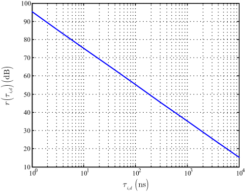
In the following, we investigate the impact of the delay difference on the IUI suppression. Here, we set and . Fig. 3 shows the the IUI suppression ratio versus the delay difference . When the delay difference , i.e.., the , the IUI suppression ratio is about dB. That is to say, long enough symbol duration is needed to maintain the IUI suppression of the proposed scheme when the delay difference is fixed.
III-B3 Power control of the uplink and downlink
If power control of the uplink and downlink is considered, the performance of the proposed INI suppression scheme may be further improved. In the following, we discuss it for two cases.
Case 1: Perfect SI mitigation at the BS.
For this case, the sum achievable rate can be expressed as
| (19) |
Remark 1: It is obviously that the sum achievable rate is increased with the downlink transmit power . Thus, the downlink transmit power should be set to the largest.
Remark 2: The first term of the is decreased with the uplink transmit power and the second term is increased with . Thus, the uplink transmit power may exist a optimum transmit power between the and the maximum uplink transmit power. Specially, when the received SNR of the uplink is much greater than one, i.e., , we can get . Obviously, the sum achievable rate is increased with the uplink transmit power . In this situation, the uplink transmit power should be set to the largest.
Case 2: Imperfect SI mitigation at the BS.
Since the INI suppression signal is retransmitted for this case, it is hard to give the explicit expression.
Up to data, many researchers have devoted to INI suppression using the power control, please refer to [36, 37, 38, 39, 40] and the referees therein.
Specially, a simple power control scheme is proposed in [39]. In this literature, the SI and the INI are both taken into account for power control optimization in single-cell and multi-cell FD networks. They show that the binary feature in sum rate-optimized power control solution holds, even when applying the INI suppression techniques referred by the method used in the multi-access channel. Thus, the proposed INI suppression scheme can be companied with this power control scheme. Since this study is too complicated, we leave it for future work.
III-B4 Imperfect channel information
Usually, we have perfect knowledge of the uplink channel and imperfect channel information of the downlink and IUI channels because of limited feedback bandwidth. Assuming that we the perfect amplitudes of the downlink and IUI channels and the their phases obeys uniform distribution, i.e., and , , , where represents the uniform distribution in interval .
Let and , where and are specific phase values. Thus, the average INP becomes
| (20) |
Let and and are independent. The distribution function of the can be calculated as follows:
When ,
| (21) |
When ,
| (22) |
The probability distribution function (PDF) of is
| (26) |
Thus, the expectation of the , where is a constant, is
| (27) |
Therefore, the INP becomes
| (28) |
It is obviously that INP reaches the minimum when the amplitude of the weighted coefficient is zero, i.e., . Notice that this conclusion holds on when any of the phase of the the downlink and interference channels is uniformly random.
Remark 1: The proposed INI suppression scheme fails in the situation when the phase information of the cam not be obtained. On the other hand, partial or precise phase information of the downlink and interference channels at the BS is necessary.
III-B5 Limited total transmit power
In practice, the total transmit power is limited. In the following, we total available power is . For simplify, the uplink and downlink power is the same.
We assume that the uplink, the downlink, and the interference channels are Rayleigh fading. We assume that the transceiver transmits signals in uniform power. We also assume that . and .
To evaluate the performance of proposed IUI suppression scheme, four scenarios are considered as follows. Case one, the networks works in HD mode. Case two, the networks works in ideal FD mode without IUI. Case three, the networks works in practical FD mode with IUI but no any IUI suppression technique is adopted. Case four, the networks works in practical FD mode with IUI suppressed by the proposed IUI scheme.
In the following, we first give the sum achievable rate of the four cases and then energy efficiency.
a): Sum achievable rate
For case one, the network works in HD mode. We assume the uplink ratio is , then the downlink ratio is . The sum achievable rate is
| (29) |
For case two, the network works in FD mode while no IUI exists. In practice, this case occurs when the downlink user is hidden from the uplink user. The sum achievable rate is
| (30) |
For case three, the sum achievable rate is
| (31) |
For case four, sometimes in practice, if the uplink channel power is small, it needs to control the usage of the proposed IUI suppression method. Thus, we introduce the threshold coefficient of the uplink channel power which decides whether the BS attempts to or not suppress the IUI222When the threshold coefficient of the uplink channel power , the results are in theory. In the following, we set . Moreover, the simulation results are similar to the situation when in our parameter set.. If , the BS decides to transmit the extra signal to suppress the IUI. In other situation, the BS keeps silent. The sum achievable rate of three nodes network can be expressed as
| (32) |
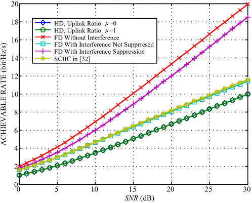
Fig. 4 shows the sum achievable rate versus SNR for five cases besides the SCIIC scheme in [33]. The gap between the ideal FD mode without interference and the FD mode with IUI suppression by the proposed scheme in this paper almost keep constant from dB to dB SNR, where . In addition, the proposed scheme performs better than SCIIC. However, the difference between the FD mode with IUI suppression by the proposed scheme and the FD mode with interference not suppressed increases with the increase of the SNR. Moreover, even the FD mode with interference not suppressed performs better than the HD mode. This result verifies that the FD operation can obtain benefit even the IUI is considered as an additive Gaussian noise at the U2 mobile receiver.
b): Energy efficiency
In the following, we assume where is the average power used for suppressing the IUI. For simplify, we assume .
For case one, it easy to know that , thus the energy efficiency is
| (33) |
For case two, also, , thus the energy efficiency is
| (34) |
For case three, also, and . The energy efficiency is
where .
For case four, the energy efficiency is
| (35) |
where
| (36) |
For case four, the transmitted power can be obtained by
| (37) |
Hence, the average transmit power can be solved by the following equation
| (38) |
The numerical algorithm of the energy efficiency calculation for case four is summarized as Algorithm 1.
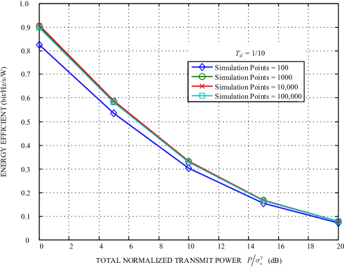
Fig. 5 shows the energy efficiency versus the total normalized transmit power for proposed IUI suppression scheme under different simulation points. The threshold coefficient of the uplink channel power is . The power threshold value of the downlink channel is . Four cases are simulated. We can see that when the simulation point is larger than , the Monte Carlo simulations for the energy efficiency are almost stable.
For the SCIIC scheme, the uplink and downlink transmit power is equal.
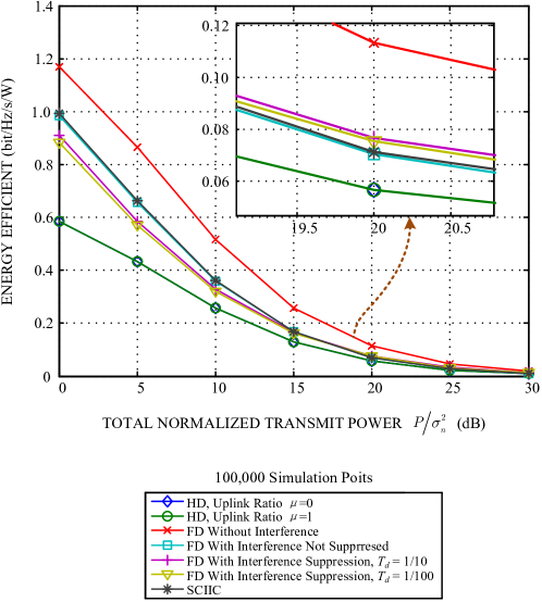
Fig. 6 shows the energy efficiency versus the total normalized transmit power for six cases besides the SCIIC scheme in [33]. The threshold coefficient of the uplink channel power . We can see that the energy efficiency of the FD mode with interference suppressed by the proposed IUI suppression scheme when the s are and is higher than the HD mode, but lower than the FD mode with interference not suppressed. The energy efficiency of the FD mode with interference suppressed by the proposed IUI suppression scheme can be improved if we adjust the . However, too large means low spectral efficiency. This result implies that there exist an obvious trade-off between the energy efficiency and the spectral efficiency. In addition, the proposed scheme performs better than SCIIC when the normalized total transmit power is more than about dB.
IV IUI Suppression Scheme for Wideband system
Here we take OFDM modulation for example.
If we extend the proposed narrowband INI suppression scheme to wideband case, there are two main realizations, frequency-domain method and time-domain scheme method.
For frequency-domain method, the INI suppression signal is weighted in the frequency-domain. In this case, INI can not be generated and transmitted at the BS until one total OFDM frame has been received. In order to improve the IUI suppression ability, the length of OFDM frame should be designed as short as possible. However, as isillustrated in Section III, to degrade the impact of the delay difference between the INI and INI suppression signals on the IUI suppression ability, the length of OFDM frame should be designed as long as possible. Thus, this conflict for frequency-domain method makes it worthless in practical application.
For time-domain method, the INI suppression signal is weighted in the time-domain. The optimum weighted coefficient for each subcarrier is translated into time-domain, we call it time-domain INI suppression (TDINIS) filter. Thus, the uplink signal can be transmitted after passing TDINIS filter as soon as it has been received. In this case, the length of OFDM frame can be set long enough while maintaining the delay difference between the INI and INI suppression signals can be minimized.
In the whole, the proposed narrowband INI suppression scheme can be extended to the wideband situation using a TDINIS filter.
V Conclusion
In mixed HD and FD networks, IUI is a key bottleneck especially when the scale of the network becomes larger. In this paper, one simple IUI suppression scheme is proposed when the BS knows the full state information of the uplink, the downlink, and the interference channels. We first investigate the effectiveness of the proposed scheme for narrowband case and then extend it to broadband case.
For the narrowband case, we evaluate the performance of the proposed scheme under practical considerations such as imperfect SI mitigation at the base station, imperfect channel information, delay difference between the IUI and the IUI suppression signals, power control and limited total transmit power. In practice, the ratio between delay difference and symbol length, e.g., the length of the OFDM frame, should be designed to be small enough to maintain performance of the proposed approach. Furthermore, besides the newest IUI suppression schemes, we compared the performance of the proposed IUI suppression scheme with the HD mode, and the FD mode with IUI but not suppressed. For achievable rate, the proposed approach outperforms other cases or schemes. For energy efficiency, the proposed approach outperforms other cases or schemes when the SNR of the channels becomes moderately high. This implies, the proposed approach prefers high SNR scene such as small or high density cell, which will be common in the next wireless communications.
In addition, when applying the proposed IUI suppression method in the FD networks, the users should be paired. How to pair the users? One gold rule is according to the quality of the uplink channel. That is to say, the quality of the interference and the downlink channels is not so important. Especially, even in the worst case that the power of the interference channel is strong and the power of the downlink channel is weak, the proposed IUI suppression method can achieve high rate, as long as the quality of the uplink channel is high. This is in contrast to the conventional viewpoint that the uplink channel power should be rationally controlled under certain level to obtain optimum sum achievable rate.
Acknowledgement
The authors would thank Qingpeng Liang for his helpful advice. This work was supported by the National Natural Science Foundation of China [grant numbers 61531009, 61471108]; the National Major Projects [grant number 2016ZX03001009]; and the Fundamental Research Funds for the Central Universities.
References
- [1] M. Duarte and A. Sabharwal, “Full-duplex wireless communications using off-the-shelf radios: Feasibility and first results,” in 2010 Conference Record of the Forty Fourth Asilomar Conference on Signals, Systems and Computers, Nov 2010, pp. 1558–1562.
- [2] J. I. Choi, M. Jain, K. Srinivasan, P. Levis, and S. Katti, “Achieving single channel, full duplex wireless communication,” in Proceedings of the sixteenth annual international conference on Mobile computing and networking. ACM, 2010, pp. 1–12.
- [3] B. Radunovic, D. Gunawardena, P. Key, A. Proutiere, N. Singh, V. Balan, and G. Dejean, “Rethinking indoor wireless mesh design: Low power, low frequency, full-duplex,” in Wireless Mesh Networks (WIMESH 2010), 2010 Fifth IEEE Workshop on, June 2010, pp. 1–6.
- [4] D. Bharadia, E. McMilin, and S. Katti, “Full duplex radios,” ACM SIGCOMM Computer Communication Review, vol. 43, no. 4, pp. 375–386, 2013.
- [5] T. Riihonen, S. Werner, and R. Wichman, “Mitigation of loopback self-interference in full-duplex MIMO relays,” IEEE Transactions on Signal Processing, vol. 59, no. 12, pp. 5983–5993, Dec 2011.
- [6] M. Jain, J. I. Choi, T. Kim, D. Bharadia, S. Seth, K. Srinivasan, P. Levis, S. Katti, and P. Sinha, “Practical, real-time, full duplex wireless,” in Proceedings of the 17th annual international conference on Mobile computing and networking. ACM, 2011, pp. 301–312.
- [7] M. Duarte, C. Dick, and A. Sabharwal, “Experiment-driven characterization of full-duplex wireless systems,” IEEE Transactions on Wireless Communications, vol. 11, no. 12, pp. 4296–4307, December 2012.
- [8] A. Sabharwal, P. Schniter, D. Guo, D. W. Bliss, S. Rangarajan, and R. Wichman, “In-band full-duplex wireless: Challenges and opportunities,” IEEE Journal on Selected Areas in Communications, vol. 32, no. 9, pp. 1637–1652, Sept 2014.
- [9] D. Kim, H. Lee, and D. Hong, “A survey of in-band full-duplex transmission: From the perspective of PHY and MAC layers,” IEEE Communications Surveys Tutorials, vol. 17, no. 4, pp. 2017–2046, Fourthquarter 2015.
- [10] Z. Zhang, K. Long, A. V. Vasilakos, and L. Hanzo, “Full-duplex wireless communications: Challenges, solutions, and future research directions,” Proceedings of the IEEE, vol. 104, no. 7, pp. 1369–1409, July 2016.
- [11] Y. Zhang, T. Liang, and A. Sun, “Improving Physical Layer Security via TAS and Full-Duplex Artificial-Noise-Added Receiver,” FREQUENZ, vol. 69, no. 7-8, pp. 357–367, JUL 2015.
- [12] F. Wu, S. Li, S. Shao, and Y. Tang, “Near-field self-interference suppression with subscriber beamforming in full-duplex communications,” AEU-International Journal of Electronics and Communications, pp. –, 2016. [Online]. Available: http://www.sciencedirect.com/science/article/pii/S1434841116307257
- [13] V. Syrjala, K. Yamamoto, and M. Valkama, “Analysis and design specifications for full-duplex radio transceivers under RF oscillator phase noise with arbitrary spectral shape,” IEEE Transactions on Vehicular Technology, vol. 65, no. 8, pp. 6782–6788, Aug 2016.
- [14] S. Goyal, P. Liu, S. Hua, and S. Panwar, “Analyzing a full-duplex cellular system,” in Information Sciences and Systems (CISS), 2013 47th Annual Conference on, March 2013, pp. 1–6.
- [15] S. Goyal, P. Liu, S. Panwar, R. A. DiFazio, R. Yang, J. Li, and E. Bala, “Improving small cell capacity with common-carrier full duplex radios,” in 2014 IEEE International Conference on Communications (ICC), June 2014, pp. 4987–4993.
- [16] D. Ramirez and B. Aazhang, “Optimal routing and power allocation for wireless networks with imperfect full-duplex nodes,” IEEE Transactions on Wireless Communications, vol. 12, no. 9, pp. 4692–4704, September 2013.
- [17] B. Yin, M. Wu, C. Studer, J. R. Cavallaro, and J. Lilleberg, “Full-duplex in large-scale wireless systems,” in 2013 Asilomar Conference on Signals, Systems and Computers, Nov 2013, pp. 1623–1627.
- [18] S. Shao, D. Liu, K. Deng, Z. Pan, and Y. Tang, “Analysis of carrier utilization in full-duplex cellular networks by dividing the co-channel interference region,” IEEE Communications Letters, vol. 18, no. 6, pp. 1043–1046, June 2014.
- [19] C. Nam, C. Joo, and S. Bahk, “Radio resource allocation with inter-node interference in full-duplex ofdma networks,” in 2015 IEEE International Conference on Communications (ICC), June 2015, pp. 3885–3890.
- [20] M. Duarte, A. Feki, and S. Valentin, “Inter-user interference coordination in full-duplex systems based on geographical context information,” in 2016 IEEE International Conference on Communications (ICC), May 2016, pp. 1–7.
- [21] G. Yu, D. Wen, and F. Qu, “Joint user scheduling and channel allocation for cellular networks with full duplex base stations,” IET Communications, vol. 10, no. 5, pp. 479–486, 2016.
- [22] A. Sahai, G. Patel, and A. Sabharwal, “Pushing the limits of full-duplex: Design and real-time implementation,” arXiv preprint arXiv:1107.0607, 2011.
- [23] N. Singh, D. Gunawardena, A. Proutiere, B. Radunovi, H. V. Balan, and P. Key, “Efficient and fair MAC for wireless networks with self-interference cancellation,” in Modeling and Optimization in Mobile, Ad Hoc and Wireless Networks (WiOpt), 2011 International Symposium on, May 2011, pp. 94–101.
- [24] J. Y. Kim, O. Mashayekhi, H. Qu, M. Kazandjieva, and P. Levis, “Janus: A novel mac protocol for full duplex radio,” CSTR, vol. 2, no. 7, p. 23, 2013.
- [25] S. Goyal, P. Liu, O. Gurbuz, E. Erkip, and S. Panwar, “A distributed MAC protocol for full duplex radio,” in 2013 Asilomar Conference on Signals, Systems and Computers, Nov 2013, pp. 788–792.
- [26] W. Choi, H. Lim, and A. Sabharwal, “Power-controlled medium access control protocol for full-duplex WiFi networks,” IEEE Transactions on Wireless Communications, vol. 14, no. 7, pp. 3601–3613, July 2015.
- [27] S. Y. Chen, T. F. Huang, K. C. J. Lin, Y. W. P. Hong, and A. Sabharwal, “Probabilistic-based adaptive full-duplex and half-duplex medium access control,” in 2015 IEEE Global Communications Conference (GLOBECOM), Dec 2015, pp. 1–6.
- [28] J. Bai and A. Sabharwal, “Decode-and-cancel for interference cancellation in a three-node full-duplex network,” in 2012 Conference Record of the Forty Sixth Asilomar Conference on Signals, Systems and Computers (ASILOMAR), Nov 2012, pp. 1285–1289.
- [29] ——, “Distributed full-duplex via wireless side-channels: Bounds and protocols,” IEEE Transactions on Wireless Communications, vol. 12, no. 8, pp. 4162–4173, August 2013.
- [30] A. Sahai, S. Diggavi, and A. Sabharwal, “On uplink/downlink full-duplex networks,” in 2013 Asilomar Conference on Signals, Systems and Computers, Nov 2013, pp. 14–18.
- [31] ——, “On degrees-of-freedom of full-duplex uplink/downlink channel,” in Information Theory Workshop (ITW), 2013 IEEE, Sept 2013, pp. 1–5.
- [32] W. Bi, X. Su, L. Xiao, and S. Zhou, “On rate region analysis of full-duplex cellular system with inter-user interference cancellation,” in 2015 IEEE International Conference on Communication Workshop (ICCW), June 2015, pp. 1166–1171.
- [33] ——, “Superposition coding based inter-user interference cancellation in full duplex cellular system,” in 2016 IEEE Wireless Communications and Networking Conference, April 2016, pp. 1–6.
- [34] V. V. Mai, J. Kim, S. W. Jeon, S. W. Choi, B. Seo, and W. Y. Shin, “Degrees of freedom of millimeter wave full-duplex systems with partial CSIT,” IEEE Communications Letters, vol. 20, no. 5, pp. 1042–1045, May 2016.
- [35] K. L. Chung, A course in probability theory. Academic press, 2001.
- [36] R. Zhang, M. Ma, D. Li, and B. Jiao, “Investigation on dl and ul power control in full-duplex systems,” in 2015 IEEE International Conference on Communications (ICC), June 2015, pp. 1903–1907.
- [37] M. Feng, S. Mao, and T. Jiang, “Joint duplex mode selection, channel allocation, and power control for full-duplex cognitive femtocell networks,” Digital Communications and Networks, vol. 1, no. 1, pp. 30 – 44, 2015. [Online]. Available: http://www.sciencedirect.com/science/article/pii/S2352864815000036
- [38] M. Al-Imari, “Theoretical analysis of full-duplex system with power control,” in 2016 International Symposium on Wireless Communication Systems (ISWCS), Sept 2016, pp. 461–465.
- [39] R. Li, Y. Chen, and Y. Wu, “Binary power control for full-duplex networks,” in IEEE 27th Annual International Symposium on Personal, Indoor, and Mobile Radio Communications (PIMRC), accepted.
- [40] J. Mairton, S. Jr, Y. Xu, G. Fodor, and C. Fischione, “Distributed spectral efficiency maximization in full-duplex cellular networks,” in 2016 IEEE International Conference on Communications (ICC), accepted.