Engineering chiral light–matter interaction in photonic crystal waveguides with slow light
Abstract
We design photonic crystal waveguides with efficient chiral light–matter interfaces that can be integrated with solid-state quantum emitters. By using glide-plane-symmetric waveguides, we show that chiral light-matter interaction can exist even in the presence of slow light with slow-down factors of up to and therefore the light–matter interaction exhibits both strong Purcell enhancement and chirality. This allows for near-unity directional -factors for a range of emitter positions and frequencies. Additionally, we design an efficient mode adapter to couple light from a standard nanobeam waveguide to the glide-plane symmetric photonic crystal waveguide. Our work sets the stage for performing future experiments on a solid-state platform.
I Introduction
Waveguide quantum electrodynamics (WQED) is an attractive platform for performing experiments where a one-dimensional continuum of radiation modes interacts strongly with quantum emitters Shen2005OL . This platform has been used to demonstrate efficient single-photon generation Arcari2014PRL ; Schwagmann2011APL , few-photon nonlinearities Javadi2015NCOM , and atom–atom interactions near a photonic band edge Hood2016arXiv . The dynamics of a WQED system is ideally governed by the decay rate of the quantum emitter into the right and left propagating modes of the waveguide, however the quantum emitter generally also couples to a continuum of radiation modes outside the waveguide with a rate . This acts as a loss which spoils the ideal interaction of the emitter with the guided one-dimensional reservoir. Accordingly, much research has been devoted to designing light–matter interfaces that maximize the fraction of light emitted from the quantum emitter to the waveguide mode MangaRao2007PRB ; Bleuse2011PRL ; LeCamp2007PRL ; Lodahl2015RMP . This is known as the beta factor . Nanophotonic waveguides composed of high refractive index materials have strongly confined optical modes and when patterned with photonic nanostructures can both suppress coupling to radiation modes using a photonic bandgap and further enhance coupling to the waveguide mode by reducing its group velocity . Such systems can be efficiently combined with solid-state quantum emitters such as quantum dots Lodahl2015RMP with near-unity values of being demonstrated recently Arcari2014PRL .
An exciting development in WQED systems is the demonstration of chiral light–matter interaction, i.e., when the symmetry between emission into the right- and left-propagating modes is broken Petersen2014Science ; Sollner2015NNANO ; Coles2016NCOM ; Lodahl2016arXiv . Since the Hamiltonian in these systems is not symmetric under time-reversal Stannigel2012NJP , they can be used to construct optical isolators and circulators Xia2014PRA ; Sollner2015NNANO ; Sayrin2015PRX ; Scheucher2016arXiv as well as to dissipatively prepare entangled states in a cascaded spin network Stannigel2012NJP ; PichlerPRA2015 . In the extreme case this interaction can also become unidirectional, i.e., the emitter couples only to a single direction. Unidirectional emission occurs when the transition dipole moment of the emitter couples to the waveguide mode in one direction while being orthogonal to the mode in the other direction. This has been achieved by engineering the modes of the nanophotonic waveguide to have an in-plane circular polarization. The modes of a dielectric waveguide are time-reversal symmetric and therefore and implying that counter-propagating modes are counter circulating. An ideal WQED system with a chiral light-matter interface exhibits unidirectional emission and also minimizes the coupling fraction to radiation modes. The fraction of light coupled to a single directional mode is characterized by the directional beta factor Lodahl2016arXiv , where the subscripts and refer to right or left respectively. In this manuscript we show that an ideal chiral light-matter interface can be achieved in a glide-plane waveguide. Unlike in previous work Sollner2015NNANO ; Young2015PRL ; Lang2016arXiv , we show that in-plane circular polarization can be preserved in photonic crystal waveguides with glide-plane symmetry (GPWs) for group velocities as low as and that the waveguide has only a single mode. This requires carefully engineering the glide-plane waveguide to ensure that it only has a single mode while preserving its symmetry. By computing the emission properties of a dipole embedded in the waveguide, we show that the decay rate of emission to a single directional mode can be enhanced by a factor of 5 while maintaining directional beta factors of . Finally, we design an efficient mode adapter to couple between a regular suspended nanobeam waveguide and our GPW.
II Engineering light-matter interaction in glide-plane waveguides
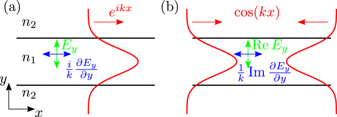
Before presenting our design we briefly discuss the requirements for realizing a waveguide whose modes have an in-plane circular polarization. The first requirement is that the waveguide modes have a longitudinal field component thus requiring non-paraxial wave propagation. The longitudinal field component must also be out of phase with the transverse field component. Fortunately, it has been shown that the magnitude of the longitudinal component of the electric field of a confined mode is proportional to the strength of its transverse confinement Bliokh2012PRA ; Lodahl2016arXiv and that Gauss’s Law ensures that the longitudinal component is out of phase with the transverse component. This is illustrated in a simple example in Fig. 1(a) which shows a schematic of the field in a two-dimensional nanophotonic waveguide. Since the geometry is piecewise homogeneous, within the waveguide Gauss’s Law requires that . The field of the waveguide is given by and therefore the waveguide mode must possess a longitudinal field component given by . We note that this argument only holds if eigenstates of the waveguide are forward and backward propagating modes. If the forward and backward propagating states are coupled, for example by creating a cavity, the mode becomes a linear combination of these states. The limit of where the eigenmodes are complete standing-waves is shown in Fig. 1(b). Here, since the mode is a linear combination of the forward and backward propagating modes, it becomes a real-valued field and cannot possess an in-plane circular polarization.
Although photonic-crystal waveguide (PCW) modes are more complex than the simple schematic shown in Fig. 1, the same arguments can be used to determine whether its modes have an in-plane circular polarization. Importantly, the presence of a band-edge occurring at the Brillouin zone (BZ) boundary , where is the Bloch wavevector and is the lattice period, sets the same restrictions on the mode profile Sukhorukov2009JoptA . In particular, if the dispersion is quadratic the field becomes a real-valued standing wave and does not have circularly polarized modes Lang2016arXiv . This follows due to time-reversal symmetry and crystal periodicity giving the relation
| (1) |
as the two zone edges are separated by a reciprocal lattice vector . This means that regular PCWs have modes that are standing waves near the band-edge and cannot have an in-plane circular polarization. We emphasize that the behaviour near the band edge is of importance as this is the regime of slow light.
This constraint can be overcome by introducing glide-plane symmetry to the waveguide. A glide-plane operation is a reflection about a plane followed by a translation. Figure 2(a) shows a GPW that is invariant under a reflection about the - plane followed by a translation of along the -direction. We denote the glide-plane operator , where is the half-period translation operator and is the reflection operator. Since the GPW is invariant under the operation , its electric field eigenstates are also eigenstates of . To find the eigenvalues of , we note that two glide-plane operations correspond to a translation along a unit cell. Therefore and thus . Importantly, at the Brillouin zone edge and thus the eigenvalues of the glide-plane operator are . This means that two positions in the GPW separated by a glide-plane symmetry operation differ by a factor of and therefore the field cannot be entirely real at the zone edge. To satisfy time-reversal symmetry there must be a second mode at the zone edge with the same frequency which is related to the first through
| (2) |
In contrast to Eq. 1 this generally implies that and are complex fields and does not constrain their polarization properties. Under these conditions the modes generally have a linear dispersion relation with equal and opposite group velocities at the Brillouin zone boundary.
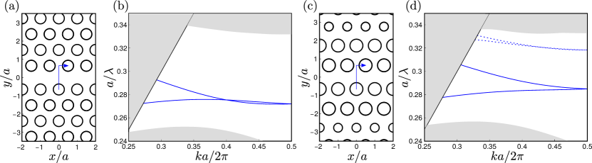
A schematic of a GPW with a hole-to-hole-centre width of between the centre of holes on the two sides of the waveguide is shown in Fig. 2(a) with its dispersion curve shown in Fig. 2(b). For all calculations the radii of the cylinders are unless otherwise stated, the membrane thickness is with a refractive index of corresponding to GaAs at cryogenic temperatures. All dispersion curves are for three-dimensional structures and are computed using freely available software Johnson2001OE . As predicted, the combination of time-reversal symmetry and glide-plane symmetry causes a degeneracy at the BZ boundary. Unfortunately, the dispersion curve has multiple modes as the two curves cross in Fig. 2(b). We note the difference to topologically-protected edge states, which can be designed to guarantee a single Dirac point Hasan2010RMP . This is problematic because, due to Eq. 2, the two modes will tend to have opposite handed circular polarizations at a given position and therefore at such a position an emitter will couple to two counter-propagating modes destroying the directionality of the system.
To make this waveguide optimum for chiral light-matter interaction we must engineer the dispersion of the waveguide Frandsen2005OE to ensure that the waveguide bands are single moded. This involves changing the radius and position of the holes around the waveguide. Since the electric field has different field profiles along the dispersion curve, perturbations to the holes affect the frequency of the modes at different wavevectors differently, i.e., the perturbation matrix element varies with , where is some perturbation to the permittivity distribution of the GPW. We vary the hole positions and radii until the bands have the desired single mode dispersion. The GPW schematic shown in Fig. 2(c) has been engineered to have the single mode dispersion curve shown in Fig. 2(d). We end up with a design where rows two to four are shifted outwards by , , and , and the radii of the first three rows of holes are modified to , , and .
III Results
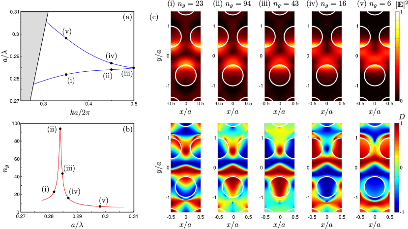
Figure 3(a) shows a close-up of the dispersion curve of the GPW and Fig. 3(b) shows the slow-down factor given by the group index where is the speed of light in vacuum. The group index becomes as large as implying a significant increase in the light-matter interaction. The electric field intensity of the modes is shown in the top panel of Fig. 3(c) while the bottom panel shows the directionality , with and where and are unit vectors. Since there is only one GPW mode, determines the fraction of light emitted to the right or left within the waveguide, i.e., implies the field is entirely left-hand circularly polarized, implies the field is entirely right-hand circularly polarized while corresponds to linear polarization. Therefore an emitter with a circularly polarized transition dipole moment positioned at a point with will emit unidirectionally within the waveguide mode. We highlight that there are many positions with for all frequencies and even for group indices up to . Importantly the shape of the Bloch modes is also such that the field has a significant fraction of its maximum intensity near the positions where the field is circularly polarized. A quantum dot that is well-coupled to the mode is therefore also likely to be at a position of high directionality.
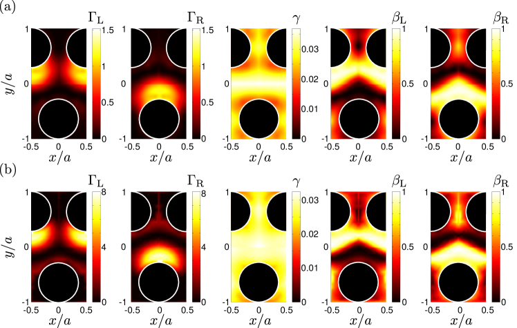
To fully appreciate the properties of the GPW for chiral light-matter interaction we quantify the fraction of emission that couples to the guided modes of the waveguide and the emission that couples to other modes. Figure 4 shows the results of computing the emission profile of a dipole for different positions within a unit cell of the GPW for two different frequencies. These computations were carried out using frequency-domain finite-element modelling software. Further details of these calculations can be found in Javadi2014InPrep . Unlike the eigenmode calculations shown in Fig. 3, these calculations enable us to also quantify the coupling to the radiation reservoir and extract the decay rate . Since these computations are considerably more time consuming, and because quantum dots cannot lie within the air holes, we have restricted the computation to positions within the GaAs. Both at and at , corresponding to Figs. 4(a) and (b) respectively, the directional beta factors approach unity. This is because the large refractive index contrast and the photonic bandgap inhibit coupling to the unguided radiation reservoir and the emission is dominated by the waveguide mode. We find that at the directional coupling rates and exhibit strong Purcell enhancement of up to 8. Purcell enhancement can help overcome decoherence processes in solid-state emitters Lodahl2015RMP . At this frequency we have found positions where while . Such parameters indicate that the GPW constitutes an almost ideal WQED geometry with chiral light-matter interaction.
We note that chiral light-matter interaction in solid-state systems has been demonstrated in regular nanobeam waveguides Coles2016NCOM . By computing the emission properties in this waveguide, we have found that the directionality factor approaches unity, but the factor has a maximum of (see Appendix A).
IV An efficient mode adapter
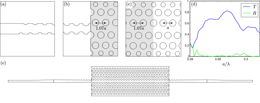
For most quantum photonics applications, it is necessary to couple light off chip Mahmoodian2016arXiv . Coupling light efficiently off chip to a fiber requires mode-matching of the tightly confined modes of the on-chip waveguides to a much larger mode confined in the core of a single-mode fiber. This is usually achieved by using inverse tapers Cohen2013OE or specially designed gratings Taillaert2006JJAP . These tapers and gratings usually complemented with standard ridge waveguides or underetched nanobeam waveguides, therefore, in order to couple light propagating in a GPW off-chip we must first demonstrate efficient coupling to a nanobeam waveguide. Unfortunately, because of the GPW’s symmetry, its modes cannot be coupled to a nanobeam waveguide directly and a mode adapter is required.
Figure 5(a)-(c) shows three segments of a mode adapter that couples light from a suspended nanobeam waveguide of width to a GPW. The purpose of the first segment in Fig. 5(a) is to adiabatically break the reflection symmetry of the nanobeam about the - plane but preserve glide-plane symmetry in the nanobeam. We do this by introducing cylindrical indentations into the side of the nanobeam. These are made by removing the high index material of the nanobeam that overlaps with circles positioned at whose radius starts at and increases linearly until the twelfth cylinder which has radius which is the same as the radius of the first row of holes in the GPW. After this section of the taper the mode has the same symmetry as the GPW. Figure 5(b) shows the second part of the mode adapter where the glide-plane symmetric nanobeam couples to a GPW whose lattice constant has been stretched to . The lattice stretching has been used for regular photonic crystal waveguides Hugonin2007OL and has the effect of shifting the dispersion curve lower. For the frequencies of interest this means that the group index of the stretched region is lower and ensures there is not a significant impedance mismatch between the nanobeam and the stretched GPW. This can then be directly coupled to the GPW with lattice constant . Just as in regular PCWs, evanescent modes help match the mode of the stretched GPW to the regular GPW to ensure efficient coupling deSterke2009OE . The transmitted power through the mode adapter to a GPW and out through a mode adapter again is shown in Fig. 5(d). We emphasize that the light propagates through the mode adapter twice. The fraction of transmitted power is comparable to coupling from a nanobeam waveguide to a regular PCW and peaks at 0.82. Here the losses are dominated by scattering into other modes. The transmission through the structure exceeds 0.6 between and .
V Conclusion
Future experiments exploiting chiral light-matter interaction such as dissipatively generating entangled dark states PichlerPRA2015 , performing two-qubit parity measurements Mahmoodian2016arXiv , or realizing non-reciprocal photon transport Sollner2015NNANO all require ideal chiral interactions between a one-dimensional radiation bath and quantum emitters. We have shown that glide-plane waveguides provide unidirectional emission and near-unity -factors and that, when interfaced with high-quality solid-state quantum emitters, can form a platform for performing the next generation of experiments.
Funding
We gratefully acknowledge financial support from the Villum Foundation, the Carlsberg Foundation, the Danish Council for Independent Research (Natural Sciences and Technology and Production Sciences), and the European Research Council (ERC Consolidator Grants ALLQUANTUM and QIOS).
Acknowledgments
The authors would like to thank Alisa Javadi and Leonardo Midolo for enlightening discussions.
Appendix A Appendix
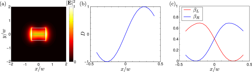
Nanobeam waveguides have also been used to demonstrate chiral light-matter interaction with near-unity values of directionality being reported Coles2016NCOM . Here we briefly evaluate their properties numerically. Figure 6(a) shows the electric field intensity of the mode of a nanobeam waveguide at a frequency where the waveguide has a single mode forward and backward mode. By computing the emission properties of a dipole with positions along the green line in Fig. 6(a) we extract the directionality and directional beta factors . Figure 6(b) shows that the nanobeam waveguide contains positions where the emission can be completely unidirectional, which is in agreement with the experimental results in Coles2016NCOM . However, the absence of slow light and a photonic bandgap in the nanobeam waveguide causes a larger fraction of the emission to couple to radiation modes outside of the waveguide. This is encapsulated by the directional beta factor plotted in Fig. 6(c). Here the directional and approach values only as large . Although the nanobeam waveguide provides a simple geometry for obtaining chiral light-matter interaction, it is less efficient than the GPW.
References
- (1) J. T. Shen and Shanhui Fan. Coherent photon transport from spontaneous emission in one-dimensional waveguides. Opt. Lett., 30:2001, 2005.
- (2) M. Arcari, I. Söllner, A. Javadi, S. Lindskov Hansen, S. Mahmoodian, J. Liu, H. Thyrrestrup, E. H. Lee, J. D. Song, S. Stobbe, and P. Lodahl. Near-unity coupling efficiency of a quantum emitter to a photonic crystal waveguide. Phys. Rev. Lett., 113:093603, 2014.
- (3) A. Schwagmann, S. Kalliakos, I. Farrer, J. P. Griffiths, G. A. C. Jones, D. A. Ritchie, and A. J. Shields. On-chip single photon emission from an integrated semiconductor quantum dot into a photonic crystal waveguide. Appl. Phys. Lett., 99:261108, 2011.
- (4) A. Javadi, I. Söllner, M. Arcari, S. Lindskov Hansen, L. Midolo, S. Mahmoodian, G. Kiršanskeė, T. Pregnolato, E. H. Lee, J. D. Song, S. Stobbe, and P. Lodahl. Single-photon non-linear optics with a quantum dot in a waveguide. Nat. Commun., 6(8655), 2015.
- (5) J. D. Hood, A. Goban, A. Asenjo-Garcia, M. Lu, S.-P. Yu, D. E. Chang, and H. J. Kimble. Atom-atom interactions around the band edge of a photonic crystal waveguide. arXiv:1603.02771, 2016.
- (6) V. S. C. Manga Rao and S. Hughes. Single quantum-dot Purcell factor and -factor in a photonic crystal waveguide. Phys. Rev. B, 75:205437, 2007.
- (7) Joël Bleuse, Julien Claudon, Megan Creasey, Nitin S. Malik, Jean-Michel Gérard, Ivan Maksymov, Jean-Paul Hugonin, and Philippe Lalanne. Inhibition, enhancement, and control of spontaneous emission in photonic nanowires. Phys. Rev. Lett., 106:103601, 2011.
- (8) G. Lecamp, P. Lalanne, and J. P. Hugonin. Very large spontaneous-emission Factors in Photonic-Crystal Waveguides. Phys. Rev. Lett., 99:023902, 2007.
- (9) Peter Lodahl, Sahand Mahmoodian, and Søren Stobbe. Interfacing single photons and single quantum dots with photonic nanostructures. Rev. Mod. Phys., 87:347, 2015.
- (10) Jan Petersen, Jürgen Volz, and Arno Rauschenbeutel. Chiral nanophotonic waveguide interface based on spin-orbit interaction of light. Science, 346:67, 2014.
- (11) Immo Söllner, Sahand Mahmoodian, Sofie Lindskov Hansen, Leonardo Midolo, Gabija Kirsanske, Tomamaso Pregnolato, Haitham El-Ella, Eun Hye Lee, Jin Dong Song, Søren Stobbe, and Peter Lodahl. Deterministic photon–emitter coupling in chiral photonic circuits. Nat. Nanotechnol., 10:775, 2015.
- (12) R. J. Coles, D. M. Price, J. E. Dixon, B. Royall, E. Clarke, P. Kok, M. S. Skolnick, A. M. Fox, and M. N. Makhonin. Chirality of nanophotonic waveguide with embedded quantum emitter for unidirectional spin transfer. Nat. Commun., 7, 2016.
- (13) Peter Lodahl, Sahand Mahmoodian, Søren Stobbe, Philipp Schneeweiss, Jürgen Volz, Arno Rauschenbeutel, Hannes Pichler, and Peter Zoller. Chiral quantum optics. arXiv:1608.00446, 2016.
- (14) K. Stannigel, P. Rabl, and P. Zoller. Driven-dissipative preparation of entangled states in cascaded quantum-optical networks. New J. Phys., 14(6):063014, 2012.
- (15) Keyu Xia, Guowei Lu, Gongwei Lin, Yuqing Cheng, Yueping Niu, Shangqing Gong, and Jason Twamley. Reversible nonmagnetic single-photon isolation using unbalanced quantum coupling. Phys. Rev. A, 90:043802, 2014.
- (16) Clément Sayrin, Christian Junge, Rudolf Mitsch, Bernhard Albrecht, Danny O’Shea, Philipp Schneeweiss, Jürgen Volz, and Arno Rauschenbeutel. Nanophotonic optical isolator controlled by the internal state of cold atoms. Phys. Rev. X, 5:041036, Dec 2015.
- (17) Michael Scheucher, Adèle Hilico, Elisa Will, Jürgen Volz, and Arno Rauschenbeutel. Quantum optical circulator controlled by a single chirally coupled atom. arXiv:1609.02492, 2016.
- (18) Hannes Pichler, Tomás Ramos, Andrew J. Daley, and Peter Zoller. Quantum optics of chiral spin networks. Phys. Rev. A, 91:042116, Apr 2015.
- (19) A. B. Young, A. C. T. Thijssen, D. M. Beggs, P. Androvitsaneas, L. Kuipers, J. G. Rarity, S. Hughes, and R. Oulton. Polarization engineering in photonic crystal waveguides for spin-photon entanglers. Phys. Rev. Lett., 115:153901, 2015.
- (20) Ben Lang, Daryl M. Beggs, and Ruth Oulton. Time reversal constraint limits unidirectional photon emission in slow-light photonic crystals. arXiv:1601.04591, 2016.
- (21) Konstantin Y. Bliokh and Franco Nori. Transverse spin of a surface polariton. Phys. Rev. A, 85(6):061801, 2012.
- (22) A. A. Sukhorukov, S. Ha, A. S. Desyatnikov, A. V. Lavrinenko, and Y. S. Kivshar. Slow-light vortices in periodic waveguides. J. Opt. A, 11(9):094016, 2009.
- (23) S. G. Johnson and J. D. Joannopoulos. Bloch-iterative frequency-domain methods for maxwell’s equations in a planewave basis. Opt. Express, 8:173, 2001.
- (24) M. Z. Hasan and C. L. Kane. Colloquium: Topological insulators. Rev. Mod. Phys., 82:3045, 2010.
- (25) L. H. Frandsen, A. V. Lavrinenko, J. Fage-Pedersen, and P. I. Borel. Photonic crystal waveguides with semi-slow light and tailored dispersion properties. Opt. Express, 14:9444, 2005.
- (26) Alisa Javadi et al. In preparation. 2014.
- (27) Sahand Mahmoodian, Peter Lodahl, and Anders Søresensen. Quantum networks with chiral light–matter interaction in waveguides. arXiv:1602.07054, 2016.
- (28) Justin D Cohen, Seán M Meenehan, and Oskar Painter. Optical coupling to nanoscale optomechanical cavities for near quantum-limited motion transduction. Optics express, 21(9):11227–11236, 2013.
- (29) Dirk Taillaert, Frederik Van Laere, Melanie Ayre, Wim Bogaerts, Dries Van Thourhout, Peter Bienstman, and Roel Baets. Grating couplers for coupling between optical fibers and nanophotonic waveguides. Japanese Journal of Applied Physics, 45(8R):6071, 2006.
- (30) J. P. Hugonin, P. Lalanne, T. P. White, and T. F. Krauss. Coupling into slow-mode photonic crystal waveguides. Opt. Lett., 32:2638, 2007.
- (31) C. Martijn de Sterke, K. B. Dossou, T. P. White, L. C. Botten, and R. C. McPhedran. Efficient coupling into slow light photonic crystal waveguide without transition region: role of evanescent modes. Opt. Express, 17:17338, 2009.