Acousto-optic and opto-acoustic modulation in piezo-optomechanical circuits
Abstract
Acoustic wave devices provide a promising chip-scale platform for efficiently coupling radio frequency (RF) and optical fields. Here, we use an integrated piezo-optomechanical circuit platform that exploits both the piezoelectric and photoelastic coupling mechanisms to link 2.4 GHz RF waves to 194 THz (1550 nm) optical waves, through coupling to propagating and localized 2.4 GHz acoustic waves. We demonstrate acousto-optic modulation, resonant in both the optical and mechanical domains, in which waveforms encoded on the RF carrier are mapped to the optical field. We also show opto-acoustic modulation, in which the application of optical pulses gates the transmission of propagating acoustic waves. The time-domain characteristics of this system under both pulsed RF and pulsed optical excitation are considered in the context of the different physical pathways involved in driving the acoustic waves, and modelled through the coupled mode equations of cavity optomechanics.
I Introduction
Nanomechanical systems have been widely used as transducers Cleland (2013) in sensing applications where an external force is mapped onto the motion of a mechanical resonator, which in turn is read out through electrical or optical means. Coupling such nanomechanical systems to electromagnetic waves Aspelmeyer et al. (2014) has further expanded the available experimental toolkit, enabling measurement imprecision below the standard quantum limit Teufel et al. (2009); Schliesser et al. (2009); Wilson et al. (2015), sideband cooling Chan et al. (2011); Teufel et al. (2011) and parametric amplification Rokhsari et al. (2005) of mechanical motion, and use of the mechanical resonator as an effective nonlinear medium for frequency conversion Hill et al. (2012); Dong et al. (2012); Liu et al. (2013). This latter role can be extended to situations in which radio frequency (RF) and optical waves are parametrically coupled to the same mechanical system. Achieving an RF-to-optical link is of relevance to quantum information science as a bridge between superconducting circuits whose qubits and resonators operate in the few GHz range Barends et al. (2014) and low propagation loss fiber-optical links in the 200 THz telecommunications band Andrews et al. (2014); Kurizki et al. (2015). It is also of significant interest for classical signal processing, where the low speed of sound and accompanying reduction in wavelength in comparison to an electromagnetic wave of the same frequency (a factor of in GaAs) allows one to create compact integrated filters, delay lines, and signal buffers Hashimoto and Hashimoto (2000), while an optical interface enables encoding RF signals onto an optical carrier for long-distance information transmission Urick et al. (2015).
Piezoelectric optomechanical devices Bochmann et al. (2013); Fong et al. (2014); Tadesse and Li (2014); Li et al. (2015); Balram et al. (2016) provide one route for coupling RF and optical waves. Our approach to such devices was recently described in Ref. Balram et al., 2016, where we used phononic crystal waveguides to link the propagating surface acoustic waves (SAWs) generated by an RF interdigitated transducer (IDT) to an optomechanical cavity. Here, we demonstrate the dynamic manipulation of optical and acoustic waves in this system. In particular, we show acousto-optic modulation, in which waveforms encoded on an RF carrier are mapped to the optical domain, and opto-acoustic modulation, in which optical pulses gate the transmission of propagating acoustic waves. This ability to dynamically control acoustic wave propagation through the application of optical fields is a novel functionality of these piezo-optomechanical systems, and may be particularly relevant considering the limited alternatives for achieving such functionality. Along with indicating the potential of these devices in optical and acoustic wave based signal processing, our measurements provide insights into how the different mechanisms by which we drive the optomechanical resonator (optically through photoelastic coupling or electrically through piezoelectric coupling to propagating acoustic waves) differ in their time-domain response. This behavior, which includes signatures of dynamic back-action under optical excitation, is well-modelled by the coupled cavity optomechanical interaction equations.
II Experimental platform
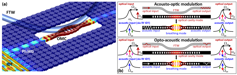
Our device architecture Balram et al. (2016) is depicted schematically in Figure 1(a). At its heart is a GaAs nanobeam optomechanical crystal cavity that supports both a localized optical mode ( 1550 nm) and mechanical mode ( 2.4 GHz), with the simulated modes displayed in Fig. 1(b). The optomechanical interaction is engineered using the photoelastic effect Chan et al. (2012); Balram et al. (2014) and the coupling strength ( MHz 60 kHz) achieved in these devices is among the highest measured for an integrated cavity optomechanical system. The mechanical motion of this breathing mode is driven due to three different sources: (i) incoherent Brownian motion due to contact with a finite temperature thermal bath; (ii) coherent RF-driven motion Bochmann et al. (2013); Fong et al. (2014); Balram et al. (2016), in which an RF signal applied to an interdigitated transducer (IDT) excites a propagating surface acoustic wave that travels through a phononic crystal waveguide and preferentially excites the breathing mode when incident on the cavity; and (iii) coherent optically-driven motion Aspelmeyer et al. (2014), wherein a phase-modulated optical signal ( ) drives the mechanical motion (the interference between the optical carrier and sideband produces a beat-note at the mechanical frequency, which drives the cavity through electrostriction). Here, we study this system in the time-domain, focusing on modulation phenomena in both the optical and acoustic domains, mediated by the optomechanical interaction and coupling to both photonic and phononic waveguides.
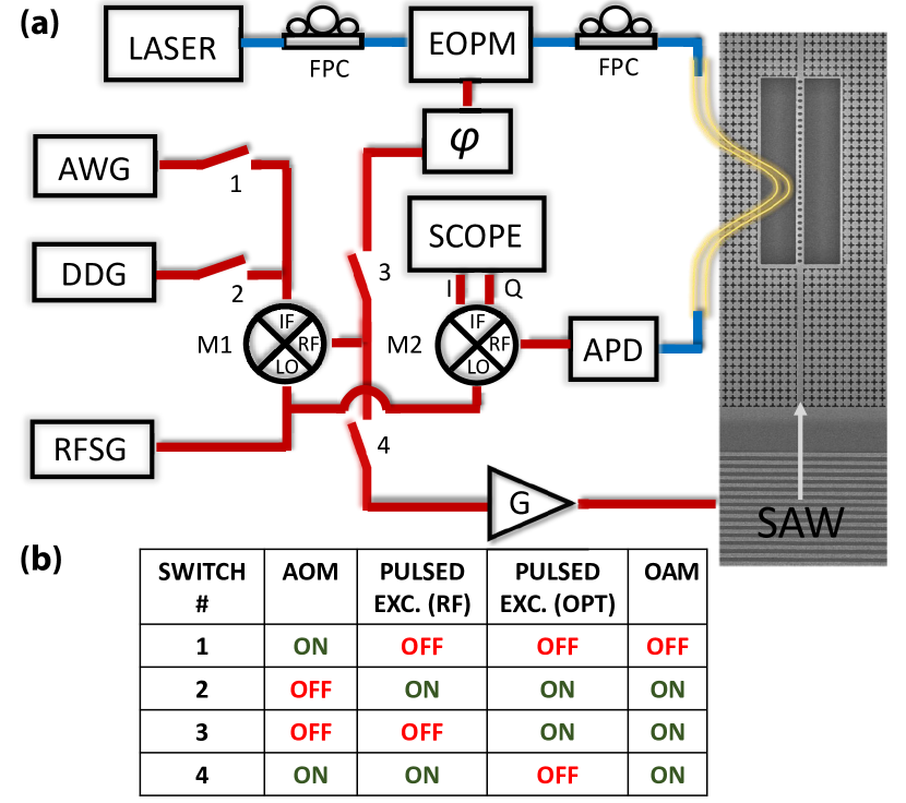
Our experimental setup is shown in Fig. 2, along with an electron microscope image of one of our devices. An arbitrary waveform generator (AWG) or digital delay generator is used to create various waveforms that can be mixed onto an RF carrier produced by an RF signal generator. This RF signal can then either be amplified and sent into an IDT, passed through a phase shifter and into an electro-optic phase modulator to generate sidebands on an optical signal that is coupled into the optomechanical cavity using a fiber taper waveguide, or both, depending on the configuration of the switches (labeled 1-4 in the diagram). The transmitted optical signal past the optomechanical cavity is photodetected with an avalanche photodiode (APD), mixed down to an intermediate frequency by using an IQ demodulator with the RF signal generator output as a local oscillator, amplified, and sent into a 8 GHz bandwidth real-time oscilloscope with a sampling rate of 25 GHz. The table at the bottom of Fig. 2 indicates the switch configurations for the different experiments we proceed to describe in the following sections.
III Acousto-optic modulation
The ability to coherently drive mechanical motion of the cavity using an applied RF signal allows us to operate the device as a resonant (in both the optical and mechanical domains) acousto-optic modulator (AOM), as depicted schematically in the top panel of Fig. 1(b). To understand the device operation, we note that the displacement amplitude of a SAW is determined by the applied RF voltage, and thus modulations in the applied voltage get mapped into modulations of the SAW amplitude. By using such propagating acoustic waves to excite the localized breathing mode of the cavity, we can transfer the RF voltage modulation to cavity mechanical mode displacement modulation. Since the optomechanical cavity converts displacement fluctuations into optical intensity or phase fluctuations (depending on the laser detuning), the transmitted optical signal thus gets amplitude or phase modulated. In our experiments, we adjust the laser detuning such that the transmitted optical signal is amplitude modulated.

To operate the piezo optomechanical circuit as an AOM, we use the setup depicted in Fig. 2 - closing switches 1 and 4 and leaving switches 2 and 3 open. The AWG produces an intermediate frequency waveform () that is mixed with the 2.4 GHz RF carrier (,) amplified, and applied to the IDT. The photodetected signal is demodulated at the frequency using an IQ demodulator, amplified, and sent to two channels of the oscilloscope, whose acquisition is triggered by the AWG.
We first identify the appropriate and available bandwidth for through thermomechanical and piezo-optical spectroscopy Bochmann et al. (2013); Fong et al. (2014); Balram et al. (2016). The thermal noise spectrum of our optomechanical cavity, under weak enough optical excitation to avoid any dynamic back-action effects, is shown in Fig. 3(a), while the photodetected signal due to coherent motion driven by the RF IDT and through a phononic waveguide, measured using the approach in Ref. Balram et al., 2016, is shown in Fig. 3(b). We confirm that 2.4 GHz is needed to drive the IDT to generate a propagating acoustic wave to match the localized breathing mode frequency, and that the breathing mode quality factor limits the bandwidth of to 1.7 MHz.
As Fig. 3(c) demonstrates, the application of different modulation signals in the RF domain (black dashed lines in the figure) results in the corresponding modulations in the photodetected optical signal. We have shown examples where is a square wave (blue), sine wave (magneta), and sawtooth wave (red), and observe faithful signal transduction from the RF to the optical domain, subject to the bandwidth limitations imposed by the mechanical cavity. The modulation effects can be understood well (Fig. 3(d)) by numerically solving the coupled equations of cavity optomechanics, which are discussed in detail in the next section. We note that in contrast to prior demonstrations of amplitude modulation in which the optical cavity was non-resonantly shaken by an incident SAW Tadesse and Li (2014); Li et al. (2015); de Lima Jr and Santos (2005), here we use the phononic waveguide to preferentially excite the localized breathing mode of the cavity, which has a high mechanical quality factor (). Moreover, the strong optomechanical coupling rate ( MHz) allows us to convert efficiently between the displacement fluctuations of the cavity breathing mode and the intensity fluctuations of the transmitted optical signal. This overall process has the potential to result in acousto-optic modulators that operate at GHz carrier frequencies with low operating voltages.
To quantify the operation of our resonant AOM, we characterize its (the voltage required to get a phase shift). By taking a ratio of the modulations obtained using a phase modulator with known and the RF signal applied to the IDT (comparing peak heights of the two CW signals in the power spectrum), we estimate = 720 mV 72 mV (the error arises primarily from the uncertainty in the reference signal and is a one standard deviation value, as discussed in the Appendix). This estimated value takes into account the (reflection) spectrum of the IDT. By optimizing the acoustic energy transfer between the SAW and the nanobeam breathing mode and improving the mechanical quality factor , we can push below 1 mV. Such low AOMs can potentially be useful for mapping weak electromagnetic signals from the RF to the optical domain Bagci et al. (2014), where they can propagate over long distances in optical fiber and be sensed by single-photon detectors. This functionality may have use in areas like radio astronomy Rohlfs and Wilson (2013), MRI Kovacs et al. (2005), and radar Eaves and Reedy (2012).
IV Optical drive, acoustic wave drive, and dynamical back action
To further explore the dynamics of our cavity optomechanical system, we excite the localized breathing mode of the cavity using RF and optical pulses and optically monitor the cavity displacement. The experimental setup is similar to that used for the AOM experiments in the previous section, except that we replace the arbitrary waveform generator with a pulse generator. The mechanical cavity displacement is probed by measuring the modulation induced on the transmitted optical signal. The mechanical cavity can be driven either through the RF channel (green curve in Fig. 4(a)) using an IDT (Fig. 2; switches 2 and 4 closed, and 1 and 3 open) or through the optical channel (blue and red curves in Fig. 4(a)) by phase modulating the optical input (Fig. 2; switches 2 and 3 closed, and 1 and 4 open), where the interference between the optical input and the phase modulated sideband drives the mechanical motion using electrostriction).

To understand the response for the different driving conditions, we can start with the optical drive. The blue curve in Fig. 4(a) corresponds to the case when the RF carrier signal () is set to a frequency that is detuned off the mechanical resonance. In this regime, the system effectively has an infinite mechanical bandwidth (no ) and the transmitted cavity signal shows a sharp rising edge. This situation corresponds exactly to putting a phase modulated signal on a bare optical cavity and measuring the transmitted amplitude modulated (AM) response (which has a rise time corresponding to the optical cavity lifetime). On the other hand, when the cavity is driven at its mechanical frequency (red curve in Fig. 4(a)), we can clearly see an evidence of dynamic back action. The probe transmission now has two time scales; a sharp step corresponding to the AM induced on the directly transmitted optical signal (this is similar to what happens in the off-resonance case) and a second slower rise that occurs due to coherent scattering of the optical pump as a result of cavity motion. To put this result in context, we note that in the frequency domain, this corresponds to the observation of coherent dynamic back action leading to optomechanically-induced transparency Weis et al. (2010); Safavi-Naeini et al. (2011).
When the system is driven through the RF channel by an IDT (green curve in Fig. 4(a)), we see a slower response. As opposed to the optical driving case where the input optical signal was phase modulated, the input optical signal here is continuous wave and the phase modulation is induced by mechanical motion of the cavity that is driven by the phononic waveguide. The timescale is thus set by the loaded mechanical quality factor of the cavity (, where the uncertainty is given by the 95 confidence interval of the Lorentzian fit shown in Fig. 3(a)). The time constants extracted from fitting the curves in Fig. 4(b) are ns 3 ns for the RF excitation and ns 4 ns for the optically driven excitation (model fit uncertainty, 95 confidence interval). These numbers agree reasonably well with the time constant ( ns 1 ns) extracted from the aforementioned value for .
We can understand and model the observed effects by using the coupled equations of cavity optomechanics:
| (1) |
| (2) |
with representing the annihilation (creation) operator for the intracavity optical field and the annihilation (creation) operator for the mechanical displacement. represents the detuning of the control beam from the optical cavity resonance frequency, the intrinsic decay rate of the optical cavity, and is the extrinsic decay rate (coupling rate) to the waveguide. represents the mechanical mode frequency, the intrinsic decay rate of the mechanical cavity, and is the extrinsic decay rate (coupling rate) to the phononic waveguide. and represent the optical and acoustic field drive strengths in the photonic and phononic waveguides, respectively, while is the vacuum optomechanical coupling rate.
We assume that we are operating in a linearized regime of small perturbations around some steady state. This allows us to model the dynamics by Fourier transforming the input signal, finding the system response to each frequency component (with appropriate phase) and inverse Fourier transforming the output. Figure 4(c) shows the results of our calculations, which faithfully reproduce the response for the optical driving (both on and off resonance) and produce the right time scales for the mechanical response. Figure 4(b) shows the experimental data plotted over the same range of timescales, indicating the correspondence with the simulations. This correspondence is also observed in the RF-driven AOM data and simulations from Fig. 3(c)-(d).
While the optically-driven response matches theory well, a closer inspection of the zoomed-in RF-driven data in Fig. 4(b) reveals some deviation from the picture we have described. In particular, the RF-driven response is not perfectly described by a single timescale, but instead seems to include a fast component and then a slower component (we note that this fast component is still much slower than the fast component in the optically-driven case). We believe the fast rise originates due to imperfect excitation of the mechanical breathing mode. While the localized breathing mode is most strongly excited by the incident acoustic wave, it can be accompanied by excitation of a variety of beam modes at the same frequency (which have low ), and these modes can also modulate the optical cavity and give rise to a fast component. In effect, in the fast regime, the system behaves like a photonic cavity that is non-resonantly modulated by the acoustic wave, which is essentially the mechanism demonstrated in previous acousto-optic modulators based on manipulating a photonic cavity with surface acoustic waves de Lima Jr and Santos (2005); Tadesse and Li (2014); Li et al. (2015). As our model neglects the potential excitation of low- modes, it fails to capture the resulting fast rise seen in the experiments. On the other hand, when the cavity is driven optically, only the localized breathing mode is excited because it is the only mechanical mode that has strong , and our model fully reproduces the experimental results.
V Opto-Acoustic Modulation
Thus far, we have probed the dynamics of our cavity optomechanical system under pulsed excitation through either the optical channel or the RF channel. However, as discussed in steady-state measurements in Ref. Balram et al., 2016, these two excitation processes can lead to interference effects in the acoustic domain as long as phase coherence is maintained between the two drive channels. In particular, by choosing the amplitude and phase of the RF excitation appropriately, one can observe destructive interference between the optically-driven and RF-driven motion. Such interference, schematically depicted in Fig. 1(b), when taken together with the ability to route acoustic waves into and out of the optomechanical cavity through phononic waveguides, results in opto-acoustic modulation - namely, the ability to gate the propagation of acoustic waves through the application of an optical control field. Although the gating requires phase coherence between the RF and optical channels, the ability to control acoustic wave propagation with optical fields is of significant interest considering the difficulty of dynamically manipulating acoustic waves through other means. In particular, while in photonics, the refractive index can be readily manipulated through free carriers, thermo-optic dispersion, and nonlinear optical processes (e.g., the Kerr effect), manipulation of acoustic wave signals would require manipulation of a material’s density or elastic constants, which are in general considerably less sensitive to external perturbations.
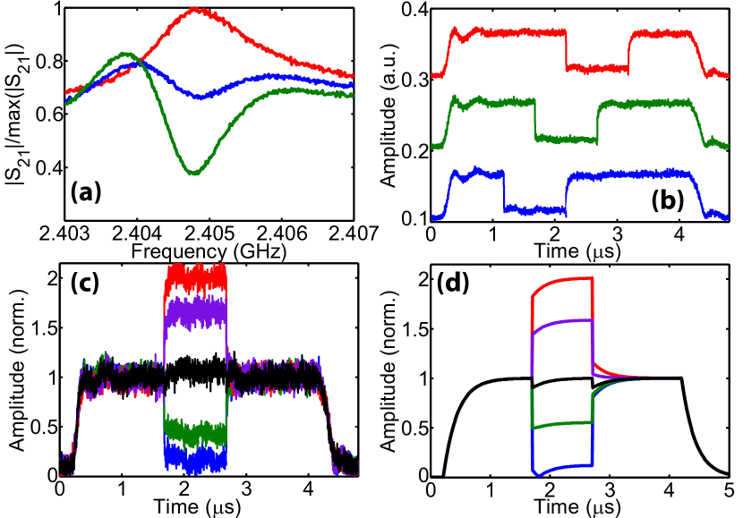
Figure 5(a) plots the transmitted probe sideband amplitude, which is effectively an optical readout of the mechanical cavity displacement amplitude, in the continuous wave (both in the RF and optical domains) case. Starting with no RF-driven motion (red curve in Fig. 5(a)), we observe optomechanically induced transparency (OMIT) Weis et al. (2010); Safavi-Naeini et al. (2011) when the system is driven by a phase-modulated optical signal. The transparency in the probe (sideband) transmission occurs due to the interference between the directly transmitted probe signal and the coherently scattered signal from the pump due to the mechanical motion induced in the cavity. By turning the RF power on and setting the phase for destructive interference, we observe a cancellation of the optomechanically-induced transparency (blue curve in Fig. 5(a)) on mechanical resonance, because the coherent motion of the cavity is zero and the scattering from the carrier to the sideband gets suppressed. Further increasing the RF power converts the transparency to an absorption dip (green curve in Fig. 5(a), corresponding to electro-mechanically induced transparency Bochmann et al. (2013); Fong et al. (2014)) as the scattered signal is now out of phase. We can use this interference effect to demonstrate optical gating of acoustic pulses.
Figure 5(b) shows the results of such experiments. We use 1 s phase-modulated optical pulses to gate the propagation of 4 s long acoustic pulses. The same RF carrier signal is fed into the two channels with a phase delay (set for destructive interference), as depicted in Fig. 2, where switches 2, 3, and 4 are closed and switch 1 is left open. By varying the time delay between the two pulses, one can carve out arbitrary 1 s chunks of the acoustic pulse using the optical pulse, as shown in Fig. 5(b). We note that the plotted amplitude in Figure 5(b)-(d) is an optical readout of the intracavity phonon population, but the same behavior will hold for the transmitted phonons as well (though any directly transmitted acoustic wave component, uncoupled to the mechanical cavity, will reduce the contrast). While the results in Fig. 5(b) represent the interaction for a phase difference () fixed for destructive acoustic wave interference, we can map out the response for the other phases as well, ranging from constructive interference (red curve in Fig. 5(c)) to destructive interference (blue curve in Fig. 5(c)), with intermediate cases shown as well. The experiment can be modelled well using the method discussed in the previous section, and the corresponding results are shown in Fig. 5(d).
VI Conclusions
We have characterized the dynamic response of GaAs piezo-optomechanical circuits to pulsed excitation in both the RF and the optical domain, where the former drives the central optomechanical cavity through an in-coupling acoustic waveguide, while the latter uses electrostrictive forces. Driving the cavity through the RF channel allows us to operate the device as a doubly resonant (for both the optical and mechanical modes) acousto-optic modulator with a mV 72 mV. Moreover, the pulsed response allows us to visualize the dynamic back action and account for the difference in the excitation characteristics through the two channels. We also use acoustic wave interference between the RF and optically driven motion to interferometrically gate the propagation of acoustic pulses through the system using optical pulses.
While RF signals have been used to excite mechanical motion in this work, our measurements focus on optical detection of the intra-cavity motion. This utilizes the exquisite sensitivity of cavity optomechanical systems to minute perturbations. In the future, we would like to extend this to detecting the transmitted / propagating phonon component, which can be done electrically through IDTs provided that the intracavity motion is efficiently transferred to an acoustic wave whose propagation characteristics are suitable for exciting the IDT. This requires further engineering of the coupling region between the propagating and localized acoustic wave resonances to reach the overcoupled regime Fang et al. (2016), and improving the overlap between the propagating acoustic wave and the IDT, for example, through the use of curved IDT geometries Wu et al. (2005). Such efforts would be key to demonstrating signal processing functionalities in which optical fields are used to manipulate radio frequency waves through acoustic tranducers, and more specifically, to efficient and bi-directional microwave-to-optical conversion.
VII Acknowledgments
K.C.B. acknowledges support under the Cooperative Research Agreement between the University of Maryland and NIST-CNST Award 70NANB10H193. J.D.S. acknowledges support from the KIST flagship institutional program.
Appendix A: Acousto-Optic Modulator
To determine the equivalent of our piezo-optomechanical circuits when operating them as acousto-optic phase modulators, we use the relationship:
| (3) |
where is the applied RF voltage to the IDT and is the modulation index imposed by the propagating SAW generated by the IDT. To determine , we use the resonant dip in the spectrum of our IDT to determine the transmitted RF voltage (in our case, the contrast is 0.25 dB, as seen in Fig. 6(b)) and a 100 load (the IDT impedance can be extracted from the spectrum) to determine the corresponding voltage. By taking the difference between on- and off-resonance reflection, we remove the background reflection that occurs due to an electrical impedance mismatch between a 50 transmission line and the IDT. In other words, our estimate of is valid for a scenario in which the IDT is impedance-matched to the RF excitation line. Achieving this in practice requires the use of balun elements for impedance matching.

To determine , we compare the peak height induced by the SAW modulation to that induced by a known optical modulation (applied using an EOPM) in the photodetected spectrum. An example spectrum is shown in Fig. 6(a). Alternately, we can also determine by comparing the height of the SAW-induced peak in the photodetected spectrum to the area of the thermal noise spectrum (broad Lorentzian curve in Fig. 6(a)), with the thermal noise spectrum being generated by contact of the mechanical resonator with the room temperature environment at 298 K (the sample is tested in ambient conditions). The error in the of the acousto-optic modulator () is dominated by the error in the of the reference EOPM ().
| (4) |
| (5) |
where is the modulation index of the phase modulator, is a constant representing the ratio of the peak heights, and is the applied RF voltage to the PM. Hence:
| (6) |
References
- Cleland (2013) Andrew N Cleland, Foundations of nanomechanics: from solid-state theory to device applications (Springer Science & Business Media, 2013).
- Aspelmeyer et al. (2014) Markus Aspelmeyer, Tobias J Kippenberg, and Florian Marquardt, “Cavity optomechanics,” Reviews of Modern Physics 86, 1391 (2014).
- Teufel et al. (2009) JD Teufel, T Donner, MA Castellanos-Beltran, JW Harlow, and KW Lehnert, “Nanomechanical motion measured with an imprecision below that at the standard quantum limit,” Nature Nanotechnology 4, 820–823 (2009).
- Schliesser et al. (2009) Albert Schliesser, Olivier Arcizet, Rémi Rivière, Georg Anetsberger, and Tobias J Kippenberg, “Resolved-sideband cooling and position measurement of a micromechanical oscillator close to the heisenberg uncertainty limit,” Nature Physics 5, 509–514 (2009).
- Wilson et al. (2015) DJ Wilson, Vivishek Sudhir, Nicolas Piro, Ryan Schilling, Amir Ghadimi, and Tobias J Kippenberg, “Measurement-based control of a mechanical oscillator at its thermal decoherence rate,” Nature 524, 325–329 (2015).
- Chan et al. (2011) Jasper Chan, TP Mayer Alegre, Amir H Safavi-Naeini, Jeff T Hill, Alex Krause, Simon Gröblacher, Markus Aspelmeyer, and Oskar Painter, “Laser cooling of a nanomechanical oscillator into its quantum ground state,” Nature 478, 89–92 (2011).
- Teufel et al. (2011) JD Teufel, Tobias Donner, Dale Li, JW Harlow, MS Allman, Katarina Cicak, AJ Sirois, Jed D Whittaker, KW Lehnert, and Raymond W Simmonds, “Sideband cooling of micromechanical motion to the quantum ground state,” Nature 475, 359–363 (2011).
- Rokhsari et al. (2005) Hossein Rokhsari, Tobias J Kippenberg, Tal Carmon, and Kerry J Vahala, “Radiation-pressure-driven micro-mechanical oscillator,” Optics Express 13, 5293–5301 (2005).
- Hill et al. (2012) Jeff T Hill, Amir H Safavi-Naeini, Jasper Chan, and Oskar Painter, “Coherent optical wavelength conversion via cavity optomechanics,” Nature Communications 3, 1196 (2012).
- Dong et al. (2012) Chunhua Dong, Victor Fiore, Mark C Kuzyk, and Hailin Wang, “Optomechanical dark mode,” Science 338, 1609–1613 (2012).
- Liu et al. (2013) Yuxiang Liu, Marcelo Davanço, Vladimir Aksyuk, and Kartik Srinivasan, “Electromagnetically induced transparency and wideband wavelength conversion in silicon nitride microdisk optomechanical resonators,” Physical Review Letters 110, 223603 (2013).
- Barends et al. (2014) R Barends, J Kelly, A Megrant, A Veitia, D Sank, E Jeffrey, TC White, J Mutus, AG Fowler, B Campbell, et al., “Superconducting quantum circuits at the surface code threshold for fault tolerance,” Nature 508, 500–503 (2014).
- Andrews et al. (2014) RW Andrews, RW Peterson, TP Purdy, K Cicak, RW Simmonds, CA Regal, and KW Lehnert, “Bidirectional and efficient conversion between microwave and optical light,” Nature Physics 10, 321–326 (2014).
- Kurizki et al. (2015) Gershon Kurizki, Patrice Bertet, Yuimaru Kubo, Klaus Mølmer, David Petrosyan, Peter Rabl, and Jörg Schmiedmayer, “Quantum technologies with hybrid systems,” Proceedings of the National Academy of Sciences 112, 3866–3873 (2015).
- Hashimoto and Hashimoto (2000) Ken-ya Hashimoto and Ken-Ya Hashimoto, Surface acoustic wave devices in telecommunications (Springer, 2000).
- Urick et al. (2015) Vincent Jude Urick, Keith J Williams, and Jason D McKinney, Fundamentals of microwave photonics (John Wiley & Sons, 2015).
- Bochmann et al. (2013) Joerg Bochmann, Amit Vainsencher, David D Awschalom, and Andrew N Cleland, “Nanomechanical coupling between microwave and optical photons,” Nature Physics 9, 712–716 (2013).
- Fong et al. (2014) King Yan Fong, Linran Fan, Liang Jiang, Xu Han, and Hong X Tang, “Microwave-assisted coherent and nonlinear control in cavity piezo-optomechanical systems,” Physical Review A 90, 051801 (2014).
- Tadesse and Li (2014) Semere Ayalew Tadesse and Mo Li, “Sub-optical wavelength acoustic wave modulation of integrated photonic resonators at microwave frequencies,” Nature Communications 5 (2014).
- Li et al. (2015) Huan Li, Semere A Tadesse, Qiyu Liu, and Mo Li, “Nanophotonic cavity optomechanics with propagating acoustic waves at frequencies up to 12 GHz,” Optica 2, 826–831 (2015).
- Balram et al. (2016) Krishna C Balram, Marcelo I Davanço, Jin Dong Song, and Kartik Srinivasan, “Coherent coupling between radiofrequency, optical and acoustic waves in piezo-optomechanical circuits,” Nature Photonics 10, 346–352 (2016).
- Chan et al. (2012) Jasper Chan, Amir H Safavi-Naeini, Jeff T Hill, Seán Meenehan, and Oskar Painter, “Optimized optomechanical crystal cavity with acoustic radiation shield,” Applied Physics Letters 101, 081115 (2012).
- Balram et al. (2014) Krishna C Balram, Marcelo Davanço, Ju Young Lim, Jin Dong Song, and Kartik Srinivasan, “Moving boundary and photoelastic coupling in gaas optomechanical resonators,” Optica 1, 414–420 (2014).
- de Lima Jr and Santos (2005) Mauricio M de Lima Jr and Paulo V Santos, “Modulation of photonic structures by surface acoustic waves,” Reports on Progress in Physics 68, 1639 (2005).
- Bagci et al. (2014) T Bagci, A Simonsen, S Schmid, LG Villanueva, E Zeuthen, J Appel, JM Taylor, A Sørensen, K Usami, A Schliesser, et al., “Optical detection of radio waves through a nanomechanical transducer,” Nature 507, 81–85 (2014).
- Rohlfs and Wilson (2013) Kristen Rohlfs and Thomas Wilson, Tools of radio astronomy (Springer Science & Business Media, 2013).
- Kovacs et al. (2005) Helena Kovacs, Detlef Moskau, and Manfred Spraul, “Cryogenically cooled probes: A leap in NMR technology,” Progress in Nuclear Magnetic Resonance Spectroscopy 46, 131–155 (2005).
- Eaves and Reedy (2012) Jerry Eaves and Edward Reedy, Principles of modern radar (Springer Science & Business Media, 2012).
- Weis et al. (2010) Stefan Weis, Rémi Rivière, Samuel Deléglise, Emanuel Gavartin, Olivier Arcizet, Albert Schliesser, and Tobias J Kippenberg, “Optomechanically induced transparency,” Science 330, 1520–1523 (2010).
- Safavi-Naeini et al. (2011) Amir H Safavi-Naeini, TP Mayer Alegre, Jasper Chan, Matt Eichenfield, Martin Winger, Qiang Lin, Jeffrey T Hill, Darrick E Chang, and Oskar Painter, “Electromagnetically induced transparency and slow light with optomechanics,” Nature 472, 69–73 (2011).
- Fang et al. (2016) Kejie Fang, Matthew H Matheny, Xingsheng Luan, and Oskar Painter, “Optical transduction and routing of microwave phonons in cavity-optomechanical circuits,” Nature Photonics 10, 489–496 (2016).
- Wu et al. (2005) Tsung-Tsong Wu, He-Tai Tang, Yung-Yu Chen, and Pei-Ling Liu, “Analysis and design of focused interdigital transducers,” IEEE Transactions on Ultrasonics, Ferroelectrics, and Frequency Control 52, 1384–1392 (2005).