Anirban Bhattacharyya, School of Computing Science, Claremont Tower, Newcastle University, Claremont Road, Newcastle upon Tyne, NE1 7RU, UK. E-mail: A.Bhattacharyya@ncl.ac.uk
An Empirical Comparison of Formalisms for Modelling and Analysis of Dynamic Reconfiguration of Dependable Systems
Abstract
This paper uses a case study to evaluate empirically three formalisms of different kinds for their suitability for the modelling and analysis of dynamic reconfiguration of dependable systems. The requirements on an ideal formalism for dynamic software reconfiguration are defined. The reconfiguration of an office workflow for order processing is described, and the requirements on the reconfiguration of the workflow are defined. The workflow is modelled using the Vienna Development Method (VDM), conditional partial order graphs (CPOGs), and the basic Calculus of Communicating Systems for dynamic process reconfiguration (basic ), and verification of the reconfiguration requirements is attempted using the models. The formalisms are evaluated according to their ability to model the reconfiguration of the workflow, to verify the requirements on the workflow’s reconfiguration, and to meet the requirements on an ideal formalism.
keywords:
dynamic software reconfiguration, workflow case study, reconfiguration requirements, formal methods, VDM, conditional partial order graphs, basic1 Introduction
The next generation of dependable systems is expected to have significant evolution requirements [CHNF10]. Moreover, it is impossible to foresee all the requirements that a system will have to meet in future when the system is being designed [MMR10]. Therefore, it is highly likely that the system will have to be redesigned (i.e. reconfigured) during its lifetime, in order to meet new requirements. Furthermore, certain classes of dependable systems, such as control systems, must be dynamically reconfigured [KMOS10], because it is unsafe or impractical or too expensive to do otherwise. The dynamic reconfiguration of a system is defined as the change at runtime of the structure of the system – consisting of its components and their communication links – or the hardware location of its software components [Bha13] or their communication links. For example, the dynamic upgrade of a software module in a telecommunications satellite during the execution of the old version of the module, the removal of a faulty controller of an aero engine during flight, re-establishing the exchange-to-mobile communication link during a conversation as the mobile crosses the boundary of communication zones, and moving an executing software object between servers to achieve load balancing. This paper focuses on dynamic software reconfiguration, because software is much more mutable than hardware.
Existing research in dynamic software reconfiguration can be grouped into three cases from the viewpoint of interference between application and reconfiguration tasks, which is embedded in time (see Figure 1). Interference is defined as the effect of the concurrent execution of a task on the execution of another task. For example, an incorrect result of a computation performed by the affected task, or a delay in the response time of the computation, or the delayed termination or replacement of the task.
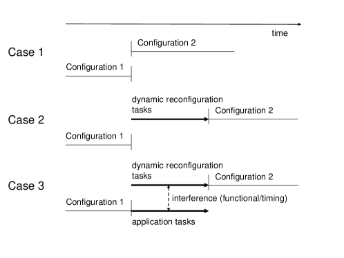
Case 1 is the near-instantaneous reconfiguration of a system, in which the duration of the reconfiguration interval is negligible in comparison to the durations of application tasks. Any executing task in Configuration 1 that is not in Configuration 2 is aborted, which can leave data in a corrupted or inconsistent state. Alternatively, the reconfiguration is done at the end of the hyperperiod of Configuration 1 (i.e. the lowest common multiple of the periods of the periodic tasks in Configuration 1), which can result in a significant delay in handling the reconfiguration-triggering event. This is the traditional method of software reconfiguration, and is applicable to small, simple systems running on a uniprocessor.
Case 2 is the reconfiguration of a system in which the duration of the reconfiguration interval is significant in comparison to the durations of application tasks, and any executing task in Configuration 1 that can interfere with a reconfiguration task is either aborted or suspended until the reconfiguration is complete. This is the most common method of software reconfiguration (see [SVK97], [AWvSN01], [BD93], and [KM90]), and is applicable to some large, complex, distributed systems. If the duration of the reconfiguration is bounded and the controlled environment can wait for the entire reconfiguration to complete, then the method can be used for hard real-time systems; otherwise, the environment can become irrecoverably unstable and suffer catastrophic failure if a time-critical service is delayed beyond its deadline.
Case 3 is the reconfiguration of a system in which the duration of the reconfiguration interval is significant in comparison to the durations of application tasks, and tasks in Configuration 1 execute concurrently with reconfiguration tasks. This method avoids aborting tasks and reduces the delay on the application due to reconfiguration, but it introduces the possibility of functional and timing interference between application and reconfiguration tasks. If the interference can be controlled, then this method is the most suitable for large, complex, distributed systems, including hard real-time systems, but it is also the least researched method of software reconfiguration. Existing research in Case 3 has focused on timing interference between application and reconfiguration tasks, and on achieving schedulability guarantees (for example, see [SRLR89], [TBW92], [Ped99], [Mon04], [FW05], and [F0̆6]). There is little research on formal verification of functional correctness in the presence of functional interference between application and reconfiguration tasks (see [MT00] and [BCDW04]).
Therefore, there is a requirement for formal representations of dynamic software reconfiguration that can express functional interference between application and reconfiguration tasks, and can be analyzed to verify functional correctness. There is also a significant requirement for modelling unplanned reconfiguration, that is, reconfiguration that is not incorporated in the design of a system (see [CHNF10], [MMR10], and [KMOS10]). This paper makes a contribution towards meeting these two key requirements. Research shows that no single existing formalism is ideal for representing dynamic software reconfiguration [Wer99]. Therefore, we use three formalisms of different kinds: the Vienna Development Method (VDM, based on the state-based approach), conditional partial order graphs (CPOGs, in which graph families are used for verification of workflow and reconfiguration requirements), and the basic Calculus of Communicating Systems for dynamic process reconfiguration (basic , based on the behavioural approach), to produce representations of a case study, and evaluate how well the different representations meet the requirements. The diversity of the three formalisms is manifested in the diversity of their semantics. Thus, VDM has a denotational semantics in order to describe data structures and algorithms, which helps to refine a specification to an implementation; CPOGs have an axiomatic semantics based on equations, which helps to make reasoning about graphs simple and computationally efficient; and basic has a labelled transition system (LTS) semantics, which helps to describe process behaviour and reconfiguration simply. In order to facilitate comparison of the formalisms, we have defined an LTS semantics for CPOGs and for the VDM model; an LTS semantics for VDM is beyond the scope of this paper.
The rest of the paper is organized as follows: Section 2 defines requirements on an ideal formalism for the modelling and analysis of dynamic software reconfiguration. Section 3 describes the case study, in which a simple office workflow for order processing is dynamically reconfigured, and defines the requirements on the initial configuration, the final configuration, and on the reconfiguration of the workflow. The case study is a modification of the case study used in [Bha13] to evaluate basic . The reconfiguration of the workflow is modelled and analyzed using VDM (in Section 4), CPOGs (in Section 5), and basic (in Section 6). We have deliberately not used workflow-specific formalisms (such as [YL05], [AP07], and [HND+11]) for two reasons. First, because of our lack of fluency in them; and second, because we believe the models should be produced using general purpose formalisms (if possible). VDM, CPOGs, and basic are compared and evaluated in Section 7 using the results of the modelling and analysis exercise and the requirements on an ideal formalism defined in Section 2. Related work is reviewed in Section 8.
This paper contains considerable material from the first author’s doctoral thesis [Bha13]. The core requirements on an ideal formalism F1–F11 in the following section are from the thesis, requirement F12 is new and was suggested by one of the anonymous reviewers. The case study is a modification of the thesis case study: Configuration 1 has been simplified by making it purely linear, Configuration 2 has been made more complex by adding concurrently executing tasks, and the reverse reconfiguration from Configuration 2 to Configuration 1 is now considered in the modelling. The descriptions of the syntax and semantics of basic are from the thesis, but the modelling now refers to all the designs of Configuration 1 (rather than to only Design 3) and the analysis based on weak observational bisimulation is new. The sections on VDM, CPOGs, and the comparison of formalisms are (of course) new.
2 Requirements on an Ideal Formalism for Dynamic Software Reconfiguration
No single existing formalism is ideal for the modelling and analysis of dynamic software reconfiguration [Wer99]. However, it is possible to identify core requirements that an ideal formalism must meet and to evaluate candidate formalisms against these requirements, such as those in this paper. In this section, we identify and briefly justify a set of core requirements, labelled F1–F12, and use them to evaluate the three formalisms in Section 7. We summarize our findings at the end of this section.
2.1 Requirements on Formalisms
We divide the requirements into two groups, the first relating specifically to modelling and verifying dynamic reconfiguration, and the second relating more generally to ‘usable’ formalisms.
Dynamic Reconfiguration Requirements
-
F1
It should be possible to model, and to identify instances of, software components and tasks, and their communication links. A software component can be a program or a class (as in Smalltalk or C++) or a module (as in C), a task is a process (as in UNIX), and a communication link is a channel of communication (e.g. a socket-to-socket link over TCP/IP between communicating UNIX processes). Multiple tasks can be based on the same software component in order to process different transactions concurrently, and multiple software components can be used to provide fault tolerance. The dynamic reconfiguration of a software component or of a task involves the selective reconfiguration of its instances, which is facilitated by the use of instance identifiers.
-
F2
It should be possible to model the creation, deletion, and replacement of software components and tasks, and the creation and deletion of their communication links. These are the fundamental operations used to change the software structure of a system.
-
F3
It should be possible to model the relocation of software components and tasks on physical nodes. Software relocation helps to implement load balancing, which is used to improve performance and reliability in cloud computing. Thus, software relocation helps to increase the dependability of cloud computing.
-
F4
It should be possible to model state transfer between software components and between tasks. In dependable systems with state, state transfer helps to implement Case 2 of dynamic reconfiguration (see Figure 1) and to implement software relocation.
-
F5
It should be possible to model both planned and unplanned reconfiguration. Planned reconfiguration is reconfiguration that is incorporated in the design of a system. Unplanned reconfiguration is reconfiguration that is not incorporated in the design of a system, which is relevant for legacy systems and for the evolution of systems.
-
F6
It should be possible to model the functional interference between application tasks and reconfiguration tasks. This is the main modelling requirement in Case 3 of dynamic reconfiguration (see Figure 1), and is an outstanding research issue.
-
F7
It should be possible to express and to verify the functional correctness requirements of application tasks and reconfiguration tasks. This is the main verification requirement of dynamic reconfiguration, and is an outstanding research issue in Case 3.
General Requirements
-
F8
It should be possible to model the concurrent execution of tasks. Concurrency can cause functional interference between tasks, and thereby affect the functional correctness of a task, and it is a feature of many dependable systems. Therefore, it should be modelled.
-
F9
It should be possible to model state transitions of software components and tasks. State affects the functionality of a task, and thereby affects the functional correctness of the task, and it is a feature of most dependable systems. Therefore, it should be modelled.
-
F10
The formalism should be as terse as possible. Terseness supports abstraction, which is essential in removing unnecessary detail from a model, and thereby renders the model easier to understand. Thus, terseness facilitates the use of a model.
-
F11
The formalism should be supported by tools. Otherwise, the formalism will not be used by software engineers.
-
F12
The formalism should be easy to learn and to use. Otherwise, the rate of adoption of the formalism by users will be low.
2.2 Summary of Results
The evaluations of the three formalisms in Section 7 show that none of them is ideal, since none of them meets all the requirements on an ideal formalism for dynamic software reconfiguration defined above. However, the formalisms meet the requirements collectively, and (therefore) are complementary (albeit with extensions).
The main strength of basic is in modelling. It can model: abstractly and tersely the composition and concurrent execution of application and reconfiguration tasks using concurrent processes, their functional interference using interleaved transitions, their planned and unplanned reconfiguration using fraction processes, cyclic processes using recursion, and reconfiguration of fraction processes using other fractions. Its main weaknesses are: inability to control non-deterministic transitions, inability to reconfigure selectively specific process instances, computational complexity of process matching based on bisimulation, computational complexity and restrictiveness of process congruence, and lack of tools.
In contrast, the main strength of CPOGs is in verification. A Boolean SAT solver can compare a model and its requirement in canonical form, and efficient model checking is supported by predicates on actions and on action dependencies and the acyclic topology of CPOGs. Correctness of a reconfiguration between configurations can be proved using consistent histories of actions of the two configurations and by restricting interference through forbidden actions. Functional interference between tasks can be modelled using either interleaved actions or simultaneous actions. Its main weaknesses are: inability to model composition and structure of software components and tasks, low level of abstraction for modelling, inability to model cyclic processes, and lack of available tools.
In contrast to both basic and CPOGs, the main strength of VDM is in formal software development. It can model workflows, software components, and tasks as data types, which facilitates their refinement to an implementation, its tools for development, simulation, and testing are mature and available, and it is easy to use by system designers. The main weaknesses of VDM-SL are: lack of constructs for modelling concurrency and interference, and lack of formal verification tools.
3 Case Study: Dynamic Reconfiguration of an Office Workflow for Order Processing
The case study described in this section involves the dynamic reconfiguration of a simple office workflow for order processing, which is a simplified version of real workflows commonly found in large and medium-sized organisations [EKR95]. Preliminary versions of the case study are in [MADB12] and [Bha13]. The case study was chosen for three reasons. First, workflows are ubiquitous, which suggests that our workflow reconfiguration will be of interest to a large community. Second, the case study is based on published work by other researchers, see [EKR95]. Third, it is both simple to understand and complex enough to exercise all three formalisms.
The workflow consists of a network of several communicating tasks, and the configuration of the workflow is the structure of the network. The workflow does not contain any loop, because loops tend to reduce the scope of reconfiguration considerably. A loop can have an invariant that is not an invariant of the reconfiguration, and thereby can prevent reconfiguration of tasks constituting the loop during an execution of the loop. The workflow contains the following tasks:
-
•
Order Receipt: an order for a product is received from an existing customer. The order identifier includes the customer identifier and the product identifier. An evaluation of the order is initiated to determine whether or not the order is viable.
-
•
Evaluation: the product identity is used to check the availability of the product; the customer identity is used to check the credit of the customer. If either check fails, the output is negative and the order is rejected; otherwise, the output is positive and the order is accepted.
-
•
Rejection: if the order is rejected, a notification of rejection is sent to the customer and the workflow terminates.
-
•
If the order is accepted, the following tasks are performed:
-
–
Shipping: the product is shipped to the customer.
-
–
Billing: the customer is billed for the cost of the product ordered plus shipping costs.
-
–
Archiving: the order is archived for future reference.
-
–
Confirmation: a notification of successful completion of the order is sent to the customer.
-
–
3.1 Configurations of the Workflow
There are two configurations of the workflow: Configuration 1 and Configuration 2. Initially the workflow executes Configuration 1. Subsequently, the workflow must be reconfigured through a process to Configuration 2. Requirements on the two configurations are shown in Figures 3.1 and 3.1 and are explained below. We then identify requirements on the reconfiguration from Configuration 1 to Configuration 2, and identify potential designs for this system.
![[Uncaptioned image]](/html/1609.08531/assets/x2.png) \captionof
\captionof
figureFlow chart of the requirements on
Configuration 1
![[Uncaptioned image]](/html/1609.08531/assets/x3.png) \captionof
\captionof
figureFlow chart of the requirements on
Configuration 2
The initial configuration of the workflow is Configuration 1 and must meet the following requirements for each order (see Figure 3.1):
-
C1.1
Order Receipt must be performed first. That is, it must begin before any other task.
-
C1.2
Evaluation: in evaluating the order, the product identity is used to perform an inventory check on the stock of the product, and the customer identity is used to perform a credit check on the customer. If either check fails, the output of Evaluation is negative; otherwise, the output is positive.
-
C1.3
Evaluation must be performed second.
-
C1.4
If the output of Evaluation is negative, Rejection must be the third and final task of the workflow.
-
C1.5
If the output of Evaluation is positive, the following conditions must be satisfied:
-
1.
Shipping must be performed after Evaluation.
-
2.
Billing must be performed after Shipping.
-
3.
Archiving must be performed after Billing.
-
4.
Confirmation must be performed after Archiving and must be the final task to be performed.
-
5.
The customer must not receive more than one shipment of an order (safety requirement).
-
1.
-
C1.6
Each task must be performed at most once.
-
C1.7
The order must be either rejected or satisfied (liveness requirement).
After some time, the management of the organization using the workflow decides to change it in order to increase sales and provide a faster service. The new configuration of the workflow is Configuration 2 and must meet the following requirements for each order (see Figure 3.1):
-
C2.1
Order Receipt must be performed first.
-
C2.2
Evaluation: in evaluating the order, the product identity is used to perform an inventory check on the stock of the product. If the inventory check fails, an external inventory check is made on the suppliers of the product. The customer identity is used to perform a credit check on the customer. If either the inventory check or the supplier check is positive, and the credit check is positive, the order is accepted; otherwise, the order is rejected.
-
C2.3
Evaluation must be performed second.
-
C2.4
If the output of Evaluation is negative, Rejection must be the third and final task of the workflow.
-
C2.5
If the output of Evaluation is positive, the following conditions must be satisfied:
-
1.
Billing and Shipping must be performed after Evaluation.
-
2.
Billing and Shipping must be performed concurrently.
-
3.
Archiving must be performed after Billing and Shipping and must be the final task to be performed.
-
4.
The customer must not receive more than one shipment of an order (safety requirement).
-
1.
-
C2.6
Each task must be performed at most once.
-
C2.7
The order must be either rejected or satisfied (liveness requirement).
3.2 Requirements on Reconfiguration of the Workflow
In order to achieve a smooth transition from Configuration 1 to Configuration 2 of the workflow, the process of reconfiguration must meet the following requirements:
-
R1
Reconfiguration of a workflow should not necessarily result in the rejection of an order.
In some systems, executing tasks of Configuration 1 are aborted during its reconfiguration to Configuration 2 (see Case 2 in Figure 1). The purpose of this requirement is to avoid the occurrence of Case 2 and ensure the occurrence of Case 3.
-
R2
Any order being processed that was received before the start of the reconfiguration must satisfy all the requirements on Configuration 2 (if possible); otherwise, all the requirements on Configuration 1 must be satisfied.
-
R3
Any order received after the start of the reconfiguration must satisfy all the requirements on Configuration 2.
3.3 Designs of the Workflow and of its Reconfiguration
The two configurations of the workflow described above are stated as requirements because there are a number of ways in which an implementation, and therefore a model, can realise the workflow. We identify four such possible designs:
-
Design 1
There is at most one workflow, and the workflow handles a single order at a time.
The workflow is sequential: after an order is received, the thread performs a sequence of tasks, with two choices at Evaluation. After the order has been processed, the thread is ready to receive a new order. This design corresponds to a cyclic executive.
-
Design 2
There is at most one workflow, and the workflow can handle multiple orders at a time.
The workflow is mainly concurrent: after an order is received, the thread forks internally into concurrent threads, such that different threads perform the different tasks of the workflow – although the requirements on the configurations severely restrict the degree of internal concurrency of the workflow – and each thread performs the same task for different orders.
-
Design 3
There can be multiple workflows, and each workflow handles a single order.
After an order is received, the thread forks into two threads: one thread processes the order sequentially – as in Design 1 – but terminates after the order has been processed; the other thread waits to receive a new order.
-
Design 4
There can be multiple workflows, and each workflow can handle multiple orders at a time.
This design is a complex version of Design 2 with multiple workflows.
In the next three sections, we model the case study workflow and its reconfiguration using three formalisms of different kinds: VDM, CPOGs, and basic . For each formalism, we use its ’idiom’ to identify which of the above four designs of the configurations is the most suitable for the formalism, which (in turn) affects how the reconfiguration of the workflow is performed. Thus, we identify which of the three cases of reconfiguration outlined in Section 1 (instantaneous, sequential, or concurrent) is the most suitable for the ’idiom’ of the formalism.
4 VDM
The Vienna Development Method (VDM) is a state-based formal method that was originally designed in the 1970s to give semantics to programming languages [Jon03]. Since then it has been used widely both in academia and industry to define specifications of software systems. It is well-suited to formalise requirements and natural language specifications and to find defects. For example, the FeliCa contactless card technology, which is widely used in Japan, was developed using VDM [FLS08]. A specification was constructed in VDM that revealed a large number of defects (278) in the existing natural-language requirements and specifications. The VDM specification was used to generate test cases and as a reference when writing the C code that was eventually deployed to millions of devices.
The VDM Specification Language (VDM-SL) was standardised as ISO/IEC 13817-1 in 1996 [ISO96]. Developments beginning in the 1990s extended the language to cover object-orientation (VDM [FLM+05]) and later to include abstractions for modelling real-time embedded software (VDM-RT [VLH06]). All three dialects are supported by two robust tools, the commercial VDMTools [Lar01] and the open-source Overture111http://www.overturetool.org/ tool [LBF+10]. These tools offer type checking for VDM models, a number of analysis tools such as combinatorial testing [LLB10], and interpretation of an executable subset of VDM that allows models to be simulated. By connecting a graphical interface to an executable model, it is also possible to animate specifications [FLS08], thereby allowing non-specialists to gain an understanding of the system described by the specification through interaction and interrogation of the model.
The models of our case study were developed in VDM-SL (using the Overture tool) and the remainder of this section uses that dialect. As part of the standardisation process, a full denotational semantics has been defined for VDM-SL [LP95], as well as a proof theory and a comprehensive set of proof rules [BFL+94]. Proofs in VDM typically verify internal consistency or are proofs of refinement [Jon90].
We proceed as follows: the VDM formalism is described in more detail in Section 4.1, the modelling of the case study is described in Section 4.2, the analysis of the model is described in Section 4.3, an LTS semantics of the model is defined in Section 4.4, and possible extensions to the model are described in Section 4.5. An evaluation of the model and formalism for describing reconfiguration is given in Section 7.
4.1 Formalism
Specifications in VDM-SL are divided into modules, where each module contains a set of definitions. Modules can export definitions to, and import definitions from, other modules in the model. The definitions in a module are divided into distinct sections and preceded by a keyword. Definitions can include types, values, functions, state, and operations. Listing 4.1 shows an empty VDM-SL module specification, divided into sections. We give an overview of the definitions later in this section, and further detail is introduced as required during explanation of the model.
A key part of the VDM-SL language is the powerful type system. VDM-SL contains a number of built-in scalar types including booleans, numeric types, and characters. Non-scalar types include sets, sequences, and maps. Custom types can be defined in the types section, based on built-in types and including type unions and record types with named fields. Custom types can be restricted by invariants and violations of these invariants can be flagged during interpretation of the models.
Functions are pure and have no side effect. They can be defined implicitly (by pre- and post-conditions) or explicitly. Explicit functions can also be protected with a pre-condition. Only explicit functions can be interpreted by the tools. State allows one or more global variables to be defined for the module. An invariant can be defined over the state to restrict its values. Again, invariant violations can be flagged during interpretation by the tool. Operations are functions that are additionally able to read and write state variables. Therefore, operations can have side effects. Like functions, operations can be defined implicitly or explicitly. Values define constants that can be used in functions and operations.
4.2 Modelling
In creating a specification that meets the workflow requirements given in Section 3, two approaches are possible in the VDM ‘idiom’. The first is to build a data model that captures an order and its status, with operations and pre-conditions ensuring that only valid transitions between statuses are possible (e.g. order receipt to inventory check). Such a model could also include details of customers and suppliers. The second approach is to model the entire workflow as sequences of actions and build an ‘interpreter’ within the model to execute and reconfigure the workflow.
These approaches are not orthogonal; a data model would complement a workflow model. The resulting specification would to be closer to any code to be written in implementing the order system than either approach separately. In this paper we follow the second approach as this more closely matches the style of the requirements on workflows described in Section 3. We return to the data model approach in Section 4.5, giving an example of how the model could be extended to incorporate a data model for orders.
As a general purpose modelling language, VDM-SL does not have built-in notions of concurrency or threading, nor does it have dedicated abstractions for modelling processes. Following a standard VDM-SL paradigm to keep the model small, a single workflow was modelled, with concurrency of the parallel actions modelled as non-deterministic interleaving; this is Design 1 from Section 3. Reconfiguration is achieved by an operation that swaps a workflow during execution of the interpeter; this is reconfiguration Case 1 as described in Section 1. In Section 4.5 we describe extensions of the model that would facilitate exploration of Designs 2–4, including features of the other VDM dialects (VDM and VDM-RT).
Analysis of the model is done through testing. This is a common way of using VDM in industry [ALR98, FLS08], using the formal model to record and test assumptions, then using the resulting model as a specification when writing code. Tests are defined for manually checking all valid configurations, and for testing valid and invalid reconfigurations. Section 4.5 explains extensions that could facilitate greater automation in testing workflows.
The following subsections explain the modelling process in detail. The model is split into three modules: Configurations, containing workflow definitions; Interpreter, containing operations to execute and reconfigure workflows; and Test, which defines test cases for the model.
The contents of the modules are described as follows: first, a set of types is defined that can capture the two workflows in the Configurations module. Next, an interpreter is defined in the Interpreter module that can ‘execute’ a workflow222Notice that the Overture tool interprets a VDM-SL specification in the sense that it does not perform a compilation beforehand. We use the term execute to describe what the interpreter in our model does to a workflow. and be reconfigured during execution. In order to test all possible paths through a configuration, a method for setting the outcome of external choices (inventory check, credit check, and supplier check) is included. The reconfiguration operation is presented in two forms: the first allows reconfiguration to any arbitrary configuration; the second extends this with a pre-condition to permit only safe reconfiguration. Finally, the Test module is described that includes operations to test all possible paths through the two configurations (in Section 4.3).
Workflows and Traces
The Configurations module defines types that are used to represent the workflows from Figures 3.1 and 3.1 and are used by the interpreter (shown later). The module also defines two constants that instantiate these workflows, a type to represent a trace of a workflow execution, and some useful auxiliary functions. The types, functions, and values of this module are made available to both the other modules using the exports all declaration:
The types for capturing workflows and their traces are built around a core type called Action, which enumerates all possible actions in a workflow (and therefore also in a trace). Any action must be exactly one of the nine listed values. The type union is defined using the pipe (|) operator, and the individual values are quote types (basic values that can only be compared for equality):
Based on this type, we define a trace as a sequence of events recording either the occurrence of an action, or a special <TERMINATE> event indicating successful completion of a workflow. The invariant on Trace states that if a termination event occurs, it must occur at the end (i.e. if it appears in a trace of elements and is not the only element, then it does not appear in the first elements):
To define a workflow type, it is necessary to allow an order for actions to be specified; this could be done with a sequence. However, in this study a recursive definition is used based around a type called Workflow:
This definition states that an Element can be one of three other types (expanded below): Simple represents a single transition such as order receipt to inventory check; Branch represents an OK? choice, such as the credit check; and Par represents parallel composition. The square brackets make the type optional, meaning that it can take a fourth special value (nil) that represents termination (the black circles in Figures 3.1 and 3.1).
The Element type can be used ‘as-is’ to represent workflow configurations, but it is not restricted in any way. For example, it can contain repeated actions (i.e. billing or shipping twice). Therefore, we introduce a Workflow type333Separating the Element and Workflow definitions is necessary in order to allow the Overture tool to check the invariant at runtime. with an invariant that prevents duplicates (by checking that for all possible traces of the workflow, the cardinality of the set of events in the trace is the same as the length of the trace).
The three types of element are defined as follows:
The above three definitions are record types, that is, compound types with named elements. Each type contains one or more actions to be executed, and one or more elements that follow this action. Therefore, the definitions are recursive, and the recursion is terminated by a nil value at each leaf. A simple workflow (called T) that rejects all orders could be defined as:
Notice that the mk_ keyword is a constructor used to instantiate values of record types. They are essentially (automatically defined) functions that construct a record with the parameters being assigned, in order, to named elements.
The Configurations module also defines two auxiliary functions that are useful for invariants and pre-conditions seen later. The first (prefixof) determines if one trace is a prefix of another and the second (tracesof) recursively computes all traces of an element:
Finally, the module defines values (constants) that describe the two configurations from Section 3, called Configuration1 and Configuration2 respectively:
Interpreter
The Interpreter module allows a workflow to be executed. The module exports its definitions so that they can be accessed by the Test module, and it imports required type definitions from the Configurations module, including the definitions of actions, the prefixof and tracesof auxiliary functions, and the values of Configuration1 and Configuration2.
In the VDM idiom, models typically have persistent state, and operations that alter this state. The state of the Interpreter module records the trace of the execution so far (trace) and the remaining workflow to be executed (workflow). A state is similar to a record type and is defined in a similar manner (the state definition acts as its own section type):
The above state definition contains an init clause that gives initial values to both components of the state (they are both ‘empty’). An invariant can also be defined with an inv clause. The module provides operations to set (and reset) the state of the interpreter, to step through execution of a workflow or execute it in a single step, and to access the current value of the trace. Operations for reconfiguration are also included and are described below (see Reconfiguration).
An operation called Init is used to prime (set and reset) the interpreter with a workflow passed as a parameter and an empty trace:
The basic operation of the interpreter is to move an action from the head of workflow and append it to the end of the trace. Once the workflow is empty, the <TERMINATE> element is added to the trace and the execution ends. Since there is no data model underlying the workflow, no additional work is done when moving an action from the workflow to the trace. However, an extension is considered towards this in Section 4.5.
The absence of a data model also means that the external choices in the workflow (the inventory check, credit check, and supplier check) must be made in some other manner. The main analysis method for this model is testing (described in Section 4.3). Therefore, it is desirable to be able to control these external choices to ensure test coverage. In order to do this, a Choices type is introduced, which is a mapping from (choice) actions to Boolean. The invariant ensures that the domain of the map is exactly the set of actions that represent external choices:
For example, a run of the workflow where there is sufficient inventory and sufficient credit can be achieved using the Choices given below. Notice that in this case a supplier check will not be needed because there is sufficient stock:
The Interpreter module defines two operations that execute a workflow, Step and Execute, with the following signatures:
The Step operation performs a single step of execution, updating the trace and moving to the next step of the workflow. This operation selects the outcome of Branch elements based on the Choices passed as a parameter, and the order of execution of actions in Par elements are selected randomly leading to interleaving of the actions. The Step operation returns the last event that occurred, which is used for reconfiguration (described below). The Execute operation uses Step operation to execute a workflow and produce a full trace. The let expression is used to ignore the value returned by Step, since it is not needed for a simple execution run:
Reconfiguration
Reconfiguration is enabled by an operation in the Interpreter module. This operation replaces the current workflow in the state by another workflow during execution. We consider the case of a single thread of execution moving from some point in Configuration1 to an appropriate point in Configuration2, with extensions discussed later.
The following operation is defined in the Interpreter module that replaces the workflow in the state by the workflow passed as a parameter to the operation. The point at which this operation is called, and the workflow passed to the operation, are left to the caller. In this way, the model is able to capture unplanned reconfiguration.
In this unprotected form, the calling thread is able to make arbitrary changes to the workflow, resulting in traces that do not meet the requirements described earlier. For example, double billing a customer by reconfiguring to a workflow with a <Billing> element after billing had already occurred. This is avoided by adding an invariant to the state that disallows configurations that could generate illegal traces. Additionally, a pre-condition is added to the Reconfigure operation to protect the invariant, ensuring that the operation only processes valid reconfigurations. Ideally, invariants should be protected by pre-conditions on operations in this fashion, so that invariants form a ‘last line of defence’.
It is a requirement that traces produced by the interpreter must be traces of Configuration 1 or Configuration 2. Therefore, the invariant states that, given the current trace (which can be empty), the remaining workflow can only produce traces valid under Configuration 1 or Configuration 2. Similarly, the pre-condition checks that the new workflow can only produce valid traces of Configuration 2 (since we currently only consider reconfigurations from Configuration 1 to Configuration 2). With the pre-condition added, the Reconfigure operation is defined as follows:
The pre-condition requires first that the new workflow is not empty. Second, the branch_check auxiliary function (described below) is used to check that the reconfiguration takes account of the outcome of branching actions. Finally, the tracesof auxiliary function is used to check that for all traces in the set of traces produced by appending the possible traces of the new configuration to the current trace, that the resulting trace is a valid trace of Configuration 2. The & denotes ‘such that’ in these quantifications. Therefore, all traces that could occur after reconfiguration are valid under Configuration 2.
The branch_check auxiliary function is defined as follows:
The above check is necessary in order to take account of the outcome of a branching action. For example, if the inventory check passes, then the external supplier check should not be performed. Since actions are not parameterised in this model, the only way to tell which branch (true or false) was taken by the action is to examine the first element of the remaining workflow, and to check that the first element of the new workflow is a valid replacement. The branch_check function explicitly encodes this checking for the inventory check and credit check. A more general solution is to pass parameters to workflow actions (e.g. to indicate the outcome of an evaluation action) and to pass a verification condition parameter to Reconfigure. Extensions are discussed in Section 4.5.
An invariant is added to the state that is defined similarly to the pre-condition of Reconfigure. However, the invariant requires that the traces must belong to either Configuration1 or Configuration2, and prefixof is used rather than equality since the trace is incomplete in the intermediate state.
4.3 Analysis
The Test module defines operations that test both configurations with the five combinations of external choices. These operations call the operations of the Interpreter module (using the back tick operator: ‘) and output the trace, which can then be printed to the console in Overture. For example, the operation that tests Configuration1 with the NoProblems choices is defined below. This operation initialises the interpreter with Configuration1, executes the interpreter and returns the completed trace:
When printed to the console, the output of the Config1NoProblems operation shows the following trace:
Tests are also defined for the other combinations of choices, and named accordingly. For example, the test where the Choices map yields false for the credit check is called Config1NoCredit (see Appendix A).
In order to test the reconfiguration operation, and demonstrate the outcome of a valid and invalid reconfiguration request, the test module defines an operation called TestReconfig, that takes the Choices required for execution (c), an action (rp) and a workflow (w) as parameters:
The operation initialises the interpreter, then steps through the execution until the action rp is seen, then attempts to reconfigure the interpreter to the workflow w. If the reconfiguration is valid under the requirements, the final trace will be printed. Otherwise, a message is printed stating that the reconfiguration is invalid (and that the pre-condition would fail if execution continued). In the model as presented, the w passed to the operation is constructed manually as a suffix of Configuration2. This is a weakness of the model. Discussion of automating such testing appears in Section 4.5 below.
Using TestReconfig, two operations are defined that demonstrate a valid and invalid reconfiguration respectively. The first, TestReconfigSuccess, reconfigures from Configuration1 to Configuration2 after the inventory check (where there is no inventory in stock, so a supplier check is performed). This is a valid reconfiguration, and the console output is as follows:
The second operation, TestReconfigFail, attempts to reconfigure from Configuration1 to the parallel composition of shipping and billing in Configuration2 after shipping has already occurred. This is an invalid reconfiguration, since shipping will occur twice. The output on the console is as below:
Notice that the Overture tool terminates with an error due to pre-condition failure:
4.4 LTS Semantics
As part of the ISO standard, a full denotational semantics has been defined for VDM-SL [LP95, ISO96]. Structured operational semantics (SOS) have also been defined for some of the new language features introduced in newer dialects [LCL13]. However, in order to facilitate comparison with the other two formalisms, we develop a labelled transition system (LTS) semantics for the VDM model. Such an LTS would be unwieldy for the whole semantics defined in the ISO standard, so we restrict this LTS to this model of the case study. This means that if the model were to be changed, the LTS would have to be updated. In the general case, this is unwieldy and is not typically part of a VDM development, but it is instructive in this instance.
The LTS rules are given in Table 1. The rules are relations that define transitions between tuples of type , corresponding to the state (S) of the interpreter. The labels on the transitions correspond to the actions that the workflow performs (which are appended to the trace), or for unobservable steps (that do not append items to the trace). The LTS rules are defined using the choices and pre_Reconfigure functions defined in the VDM model in order to render the rule definitions concise and human-readable.
The Init rule states that the interpreter can be given a workflow when it does not currently have one and its trace is empty. This is the initial state of S as defined above: init s == s = mk_S([], nil). The Terminate rule allows the interpreter to terminate when it has no workflow left. The Reset rule allows a terminated interpreter to be reset with another workflow.
The Simple, Branch-T, Branch-F, Par-1 and Par-2 rules encode the logic of the Step operation introduced above (though not given in full). They correspond to the three elements that form the Workflow type. The action of a Simple element can always happen. The action performed by a Branch action depends on the choices parameter that is passed to the Execute operation. For the Par element, the two rules have no hypotheses and therefore it is non-deterministic choice of which action is performed first. These rules make it clear that this model has an interleaving semantics. The Reconfigure rule states that the workflow that is still to be executed can be replaced in one atomic step, assuming that the new workflow will not violate the pre-condition of the Reconfigure operation.
We give three examples of application of the LTS rules in Figure 2. The first (top) demonstrates a complete run of the workflow and is equivalent to the Config1NoProblems test. The second (middle) demonstrates a run in which the credit check yields false and is equivalent to the Config1NoCredit test. The third (bottom) demonstrates a reconfiguration from Configuration 1 to Configuration 2 after the inventory check and is equivalent to the TestReconfigSuccess test. Model checking of the reconfiguration is facilitated by the trace of actions and the LTS rule applications, and is shown in Appendix B.
| nil | ||
| by Init | ||
| by Simple | ||
| by Branch-T | ||
| by Branch-T | ||
| by Simple | ||
| by Simple | ||
| by Simple | ||
| by Simple | ||
| by Terminate | ||
| nil | by Reset |
| nil | ||
| by Init | ||
| by Simple | ||
| by Branch-T | ||
| by Branch-F | ||
| by Simple | ||
| by Terminate | ||
| nil | by Reset |
| nil | ||
| by Init | ||
| by Simple | ||
| by Branch-F | ||
| by Reconfigure | ||
| by Branch-T | ||
| by Branch-T | ||
| by Par-1 | ||
| by Simple | ||
| by Simple | ||
| by Terminate | ||
| nil | by Reset |
4.5 Extensions
The model describes an interpreter with a single thread. Therefore, interference is not considered beyond the non-deterministic execution of parallel compositions. To allow multiple threads of control, the state of the interpreter must be extended to allow a set of workflows (and their associated traces) to be defined. The reconfiguration operation must then be extended to reconfigure each thread in turn. This would allow the model to exhibit concurrent application and reconfiguration actions (Case 3 in Figure 1). Actions are atomic in the current model, so there is no way to abort actions. To extend the model to allow this, a notion of beginning and completing actions would be required. This could be achieved either by having ‘begin’ and ‘end’ forms of each action, as used in [CJ07] to investigate fine-grained concurrency in programming languages, or by defining a ‘current action’ in the state, which is placed there and removed at a later state. If reconfiguration occurs between the beginning and end of an action, or if there is a current action present in the state, then an abort occurs.
As mentioned at the beginning of this section, there are two further dialects of VDM. These use VDM-SL as their core specification language, but extend it with additional features. VDM adds object-orientation and concurrency through threads. VDM-RT extends VDM to add features for modelling real-time embedded systems. These are a global ‘wall clock’ that is advanced as expressions are evaluated (to predict real-world execution time), and models of compute nodes connected by buses on which objects can be deployed. The (simulated) time taken to evaluate language expressions depends on the speed of the compute nodes and buses, and can be overridden to tune model where measurements of the actual speed of the target system can be made, in order to make better predictions of behaviour of the final code.
These two dialects are often used as part of a development process [LFW09] that begins with a sequential model of the system, which can be constructed in VDM-SL or in VDM. Conversion from VDM-SL to VDM is straightforward as the core language is the same, the main changes are to turn modules into classes and to turn the state definition into instance variables. The sequential model is then extended to allow concurrent execution, then a real-time version is made that captures the resources and configuration of the target hardware for which code will be written. VDM could be used to extend the model and capture true concurrency, allowing Designs 2, 3 and 4 (in Section 3.3) to be modelled.
In addition, extending the model to use VDM allows additional features of the Overture tool to be used. In the above model, tests were manual created and executed for all possible configurations. This is obviously cumbersome and unscalable for more complicated models. For VDM models, Overture has combinatorial testing features that allow tests to be created using regular expressions. Overture also has true unit testing for VDM models.
To extend the model to allow reconfiguration from Configuration 2 back to Configuration 1, the pre-condition on Reconfigure needs to be relaxed to permit future traces from both configurations (not just Configuration 2 in the current model). To extend the model to add further configurations, a few steps are necessary. First, the configuration must be defined as a value in the Configurations module (for example, Configuration3). Tests for this new configuration should be added to the Test module and executed. Finally, the pre-condition must be extended to consider traces of the new configuration to be valid. This is simple if it is acceptable to switch between any configuration at any time. However, the definitions would be more complicated if there were restrictions on reconfiguration. For example, if there are ‘points of no return’ in between different configurations.
In Section 4.2, extending the current model with a model of data was suggested. This extension represents an augmentation of the current workflow models with the data and operations necessary to allow customers to place orders. This could include data types for representing orders, such as the following:
The above defines identifiers for customers and orders using token types (a countably infinite set of distinct values that can be compared for equality and inequality). The Order type is a record that identifies a customer and the status of the order: whether or not the checks have been passed, and whether the order is accepted. The state of the model stores all orders in the orders map.
To continue this model, operations should be defined to receive and evaluate orders, and to accept or reject them, then to notify the customer, to bill and ship, and finally to archive. Each should manipulate the data model and be protected by pre-conditions to ensure consistency and make explicit any assumption about the system. The following implicit operation, defined only in terms of pre- and post-conditions, evaluates an order. The pre-condition states that the order must be known (in the domain of the orders state variable) and be unprocessed. The post-condition states that the orders map should contain an updated record for this order with the result of the inventory and credit check. The mu expression allows record values to be overwritten, rather than constructing a new copy with the mk_ constructor.
This extended data model could then be connected to the existing interpreter, such that when elements of the workflow are executed, calls are made to the operations that manipulate the data model. The extended model would demonstrate whether it was possible to build an actual order system that met the requirements, particularly when new configurations are introduced. The data and operations could then be used as a specification during implementation in some programming language.
5 Conditional Partial Order Graphs
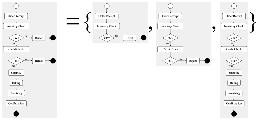
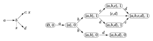
Conditional partial order graphs (CPOGs) [Mok09] were originally introduced for reasoning about properties of families of graphs in the context of asynchronous microcontroller design [MY10] and processors with reconfigurable microarchitecture [MRSY14]. CPOGs are related to featured transition systems (FTSs) that are used to model feature families of software product lines [CHS+10]. The key difference between FTSs and CPOGs is that FTSs use transition systems as the underlying formalism, whereas CPOGs are built on top of partial orders, which enables the modelling of true concurrency. In this paper, CPOGs are used to represent compactly graph families in which each graph expresses a workflow scenario (i.e. a particular collection of outcomes of branching actions of a workflow) or a particular collection of requirements on workflow actions and their order. For example, the requirements on Configuration 1 of the case study workflow (shown in Figure 3.1) can be expressed using a family of three simple (i.e. branch-free) graphs (see Figure 3). We use the term family instead of the more general term set to emphasise the fact that the graphs are annotated with branch decisions, in this case:
-
•
Inventory check OK: No
-
•
Inventory check OK: Yes, credit check OK: No
-
•
Inventory check OK: Yes, credit check OK: Yes
This can be expressed equivalently using the following predicates:
-
•
-
•
-
•
where InventoryCheck and CreditCheck are the names of the two branch actions. Henceforth, we adopt the predicate notation.
The remainder of this section is organized as follows. In Section 5.1 an axiomatic semantics of CPOGs is given and basic workflow modelling primitives are introduced, which are used in Section 5.2 to model the case study workflow and to demonstrate how CPOGs can be used for workflow verification by reduction to the Boolean Satisfiability (SAT) problem. An LTS semantics of CPOGs is defined in Section 5.3, thereby establishing a formal link with the other two formalisms discussed in this paper. Dynamic reconfiguration is discussed in Section 5.4, and we show that CPOGs use true concurrency semantics when modelling functional interference between workflow and reconfiguration actions. We comment on our experience of automating the verification of the workflow requirements in Section 5.5, and give an overall evaluation of the CPOG-based approach in Section 7.
5.1 Formalism
The axiomatic semantics of CPOGs is outlined below, and was first introduced in [MK14] to provide efficient compositionality and abstraction facilities for graphs. Each element of the algebra represents a family of graphs, and is defined as follows:
Let be the alphabet of names of actions (e.g. and ) that represent tasks and subtasks. Actions can have order dependencies between them. is used to construct models of workflows and to define their requirements using the following axioms:
-
•
The empty workflow is denoted by , that is, the empty family of graphs.
-
•
A workflow consisting of a single action is denoted simply by . It corresponds to a family consisting of a single graph that contains a single vertex .
-
•
The parallel composition of workflows and is denoted by (e.g. the concurrent execution of Billing and Shipping shown in Figure 3.1 is denoted by ). The operator is commutative, associative, and has as the identity:
-
1.
-
2.
-
3.
Intuitively, means ‘execute workflows and concurrently, synchronising on common actions’.
-
1.
-
•
The sequential composition of workflows and is denoted by (e.g. the sequential execution of Shipping followed by Billing shown in Figure 3.1 is denoted by ). The operator has a higher precedence than , is associative, has the same identity () as , distributes over , and can be decomposed into pairwise sequences:
-
1.
-
2.
and
-
3.
and
-
4.
Intuitively, means ‘execute workflow , then execute workflow ’. In other words, introduce order dependencies between all actions in and all actions in . Note that if and contain common actions they cannot be executed in sequence, as illustrated by an example below.
Figure 4 shows an example of parallel and sequential composition of graphs. It can be seen that the parallel composition does not introduce any new order dependency between actions in different graphs; therefore, the actions can be executed concurrently. Sequential composition, on the other hand, imposes order on the actions by introducing new dependencies between actions , , and in the top graph and action in the bottom graph. Hence, the resulting workflow behaviour is interpreted as the behaviour specified by the top graph followed by the behaviour specified by the bottom graph. Another example of these operations is shown in Figure 5. Since the graphs have common vertices, their compositions are more complicated, in particular, their sequential composition contains the self-dependencies and which lead to a deadlock in the resulting workflow. Action can occur, but all the remaining actions are locked: neither nor can proceed due to the self-dependencies, while cannot proceed without and . Figures 6(a) and 6(b) illustrate the distributivity and decomposition axioms respectively.
-
1.
-
•
A conditional workflow is denoted by , where is a predicate expressing a certain condition (e.g. ‘Inventory Check OK’) and is a workflow. Intuitively, means ‘execute workflow only if condition holds’. We postulate that and . This allows us to model branching in flow charts. For example, the algebraic expression
corresponds to a branching performed after action , which is followed by workflow if predicate holds, and by workflow if predicate does not hold. Alternatively, we can say that the above expression corresponds to a family of graphs, in which vertex is followed by actions from the graphs coming either from family or from family , as illustrated in Figure 6(c), where a dotted line between vertex and variable indicates that the variable is assigned a value during the execution of action . We will use the following short-hand notation for a clearer correspondence with flow charts:
where predicate ‘A OK’ corresponds to the successful completion of a branching action . For example, the expression
corresponds to the first branching in Figure 3.1: if the inventory check is completed successfully the workflow continues with the credit check, otherwise the order is rejected and the workflow ends (actions and denote respectively the start and end circles used in the flow chart). Notice that operators and bind less tightly than to reduce the number of parentheses. Operator has the highest precedence and has the following useful properties (proved in [MK14]):
1. 2. 3. 4.
Notice that the condition operator can be used not only to create conditional workflows, but also to create conditional workflow dependencies. For example, in the expression , if , the expression simplifies to the parallel composition , but if , the expression simplifies to the sequential composition . In other words, actions in conditionally depend on actions in .
To summarise, the following operators are used to create and manipulate graph
families corresponding to workflows (in decreasing order of precedence):
, , ,
, and , where is an
action, is a predicate, and and are workflows.
The algebraic notation is used to translate flow charts into mathematical descriptions amenable to automated verification, as described in the next subsection.


5.2 Modelling and Analysis
The granularity of concurrency in CPOGs is a single action, and the granularity of reconfiguration is a single action and a single dependency between actions. Multiple actions and dependencies can also be reconfigured by a single reconfiguration action that sets Boolean variables in the predicates that guard the actions and their dependencies. Thus, it is possible to model all three cases of dynamic reconfiguration identified in Section 1. A CPOG can easily express concurrent actions, and (therefore) Case 3 of reconfiguration fits the CPOG ’idiom’ best. However, we have modelled Case 1 of reconfiguration for simplicity. Notice that the different designs of the case study workflow configurations are represented as the same CPOG model, because CPOGs cannot represent cyclic processes.
We now describe how to specify workflow requirements and their reconfiguration as families of graphs, how to reason about the correctness of such specifications, and how to manipulate them using the operators of the algebra.
The algebraic notation can be used to translate the flow chart in Figure 3.1 into the following expression:
The expression can be rewritten using the axioms in order to prove that certain requirements hold. For example, any expression can be rewritten into a so-called canonical form [MK14], which is sufficient for checking most of the requirements listed in Section 3.1.
Proposition 1
Any workflow expression can be rewritten in the following canonical form [MK14]:
| (1) |
where:
-
•
is a subset of actions that appear in the original expression;
-
•
for all , are canonical forms of Boolean expressions and are distinct from 0;
-
•
for all , are canonical forms of Boolean expressions such that (that is, a dependency between actions and can exist only if both actions exist).
In other words, the canonical form of an expression lists all constituent actions and all pairwise dependencies between them (along with their predicates). The canonical form can contain redundant transitive dependencies, such as in presence of both and . Such terms can be eliminated to simplify the resulting expression. This corresponds to the well-known transitive reduction procedure, which can be formalised by adding the following axiom [MK14]:
The axiom can be used to add or to remove transitive dependencies as necessary, see Figure 6(d).
Rewriting a workflow expression manually by following the CPOG axioms is tedious and error-prone. This motivated us to automate computation of the canonical form and the transitive reduction, as will be discussed in Section 5.5. By applying these procedures to we obtain its reduced canonical form shown below. For brevity, we will denote predicates InventoryCheck OK and CreditCheck OK simply by and respectively. Actions are visually separated from dependencies by a horizontal line.
The resulting expression gives us plenty of valuable information that can be used for analysis of the workflow. In particular, the following correctness properties can be verified:
-
•
The starting and ending actions are part of the workflow regardless of possible outcomes of the branching actions, as indicated by ‘unconditional’ terms and .
-
•
The billing, shipping, archiving, and confirmation actions are performed if and only if both the inventory and internal credit checks are successful; in fact, all these actions are pre-conditioned with the predicate .
-
•
An order is rejected if either the inventory check or the internal credit check fails, as confirmed by term .
-
•
The first action after is always , as confirmed by term and the fact that all other actions transitively depend on .
-
•
The shipping and billing actions are always performed sequentially: whenever the actions occur
( and ) so does the dependency . -
•
There are no cyclic dependencies and therefore each action is performed at most once.
We now translate the workflow requirements for Configuration 2 shown in Figure 3.1 into our notation, verify several relevant correctness properties, and highlight the differences between the two configurations. The flow chart in Figure 3.1 can be translated into the following expression:
where expression corresponds to the part of the workflow starting with the action:
The ability to abstract and share/instantiate common behaviour (e.g. in the above workflow) is essential for specifying real-life reconfigurable systems, where monolithic specifications are impractical. Our prototype implementation supports abstraction and sharing (see Section 5.5 for further details).
Expression can now be prepared for further analysis by converting it into the canonical form and transitively reducing the result as described above. For brevity, we denote predicates InventoryCheck OK and SupplierCheck OK by and respectively, thereby emphasising that roles of inventory and supplier checks are similar; the predicate CreditCheck OK is denoted by as before. The resulting expression is shown below.
Using the derived expression, the following properties of Configuration 2 can be verified:
-
•
The billing and shipping actions are concurrent as indicated by the lack of any dependency between them. This is different from Configuration 1 where the actions could only occur in sequence:
. -
•
The credit check is conducted when either inventory or supplier check is successful, as indicated by term . Again, this is different from Configuration 1, where there was no way around the inventory check.
-
•
Consequently, an order is rejected under the condition , that is, when either both inventory and supplier checks have failed, or the credit check has failed. By negating this condition we obtain , which guards the billing, shipping, and archiving actions, as well as dependencies between them.
-
•
The confirmation action is missing in , as intended. We can also highlight this by adding a redundant term to .
As demonstrated above, Configurations 1 and 2 have several important differences. Hence, if a system’s configuration is dynamically changed from one configuration to another, the system may end up in an impossible state according to the new configuration. Such situations may lead to the system’s failure, and (therefore) must be prevented. In Section 5.4 we discuss how the CPOG-based modelling and verification approach can be used to describe formally such situations, determine under which circumstances they can occur, and derive practicable reconfiguration guidelines to prevent their occurrence.
5.3 LTS semantics
In this section, we define an LTS semantics of CPOGs in order to facilitate comparison with the other two formalisms. The definition is based on CPOG firing rules introduced in [Mok09] and the canonical form construction [MK14] (see Proposition 1).
According to (1), any algebraic CPOG expression can be uniquely represented by a directed graph whose vertices and arcs are labelled with Boolean conditions and (respectively) that are defined on a set of Boolean variables . A variable is said to be controlled by a vertex if the value of the variable is changed by the action associated with the vertex . Notice there is at most one such vertex for each variable. Therefore, the value of each variable can be changed at most once.
Given an assignment of variables , a vertex and an arc are termed active if their respective conditions evaluate to 1 under the assignment, denoted by and respectively; otherwise, and are termed inactive. There are possible variable assignments. Therefore, a CPOG can describe up to possible graphs comprised of active vertices and arcs.
The preset of a vertex , denoted by , is defined to be the set of active (determined by ) vertices that are connected to by active arcs :
A history is a subset of active vertices whose corresponding actions have already occurred. The number of possible histories is bounded by .
A labelled transition system (LTS) is a triple , where is the set of states, is the alphabet of actions that label state transitions, and is the transition relation. We will use the shorthand notation to denote belongs to the relation .
A CPOG defines an LTS with states that correspond to all possible histories and variable assignments. Hence, every state is a pair . We fix the initial state to be equal to where is the zero variable assignment: for all .
The alphabet of actions of the LTS directly corresponds to the CPOG vertices. Therefore, .
The transition relation can be captured by the following rule:
In other words, the system can transition from state to state by executing the action corresponding to an active vertex if the vertex preset belongs to the history and the action has not been performed previously. The new variable assignment must be identical to the old variable assignment on all variables that are not controlled by vertex .
Notice that the above rule defines the execution of a single action, and thereby defines an interleaving semantics for pseudo-concurrent actions. In order to define the semantics of true concurrency, the LTS syntax must be extended to enable a set of actions to be performed simultaneously, which results in the following alternative rule for the transition relation:
Thus, the alternative rule allows multiple actions in a set to be performed simultaneously. Hence, every diamond
is augmented with a diagonal transition .
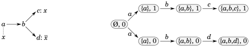
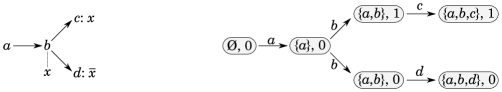
Figure 7 shows three CPOG examples and the corresponding LTSs. The states are denoted by grey ovals with the history/assignment pairs, for example means and . The first CPOG corresponds to a system with two possible sequential behaviours: (when ) and (when ), where the choice between and is made during the execution of action by appropriately setting variable , as denoted by the dotted line between and (hence, using the above notation). The corresponding LTS (on the right-hand side) contains a non-deterministic choice in the initial state . The second CPOG shown in Figure 7(b) contains the same set of behaviours, but the choice is delayed until action . Notice that the corresponding LTS is not bisimilar to the previous one. Finally, the example in Figure 7(c) shows a CPOG containing a sequential behaviour (when ) and a concurrent behaviour (when ). The corresponding LTS shows the effect of combinatorial state explosion due to concurrency; the single step transition is shown with a dotted arc.
Reconfiguration example
We now give an example illustrating CPOG LTS semantics in the presence of dynamic reconfiguration. Figure 8 (top) shows two system configurations: , where actions and can execute in parallel, and , where and are executed in sequence. This example is based on our case study, with and corresponding to and respectively.
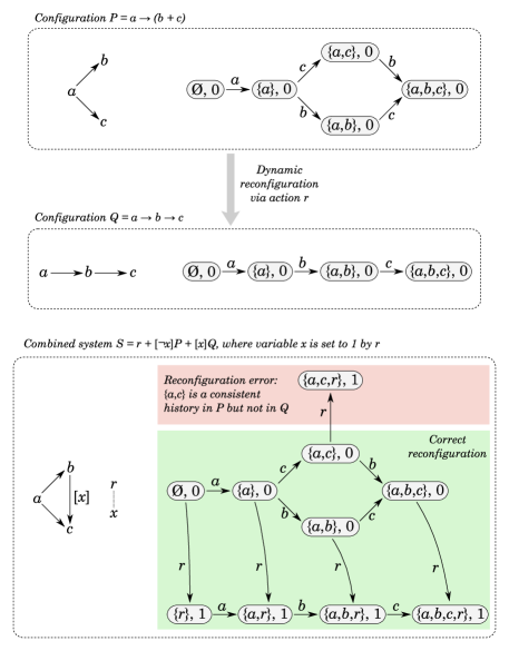
We algebraically combine and to form , where variable indicates the completion of the reconfiguration action that reconfigures the system from to . The LTS semantics of the complete system is shown in Figure 8 (bottom). Notice that actions and the reconfiguration action are concurrent. The LTS shows the interference between the reconfiguration and computation actions, specifically, if is executed after in state of then the history of the resulting state with elided is an inconsistent history of , since cannot execute before in . In the next section, we discuss interference in more detail and show how we can derive reconfiguration guidelines that restrict concurrency and guarantee the system does not reach an inconsistent state due to reconfiguration. In this example, such a guideline is: reconfiguration action should be executed before action , which makes the inconsistent state unreachable.
The above example illustrates that CPOG theory and LTS semantics apply to both computation and reconfiguration actions. Therefore, a special reconfiguration rule is not required.
5.4 Dynamic reconfiguration
In this section, we show how CPOGs can be used to reason about dynamic reconfiguration, in particular, how to prove reconfiguration requirement R2 in Section 3.2. We start by elaborating the important notion of history from the previous section, which allows reasoning about states of a system whose behaviour is described by a CPOG specification.
A history is a set of actions that have occured in a system up to a certain moment in time. The set must be causally closed, that is, if an action has occured then all the actions it depends on must also have occurred. However, since CPOGs are capable of describing not just single workflows but families of workflows, the notion of causality must be clarified. In fact, we can only talk about conditional causality, where an action depends on another action under a condition , or algebraically: . This leads to the following notion of consistency.
Given a history and a CPOG specification , we define the consistency condition under which all actions in could have occurred without violating the specification as follows:
| (2) |
where and are from the canonical form of the specification (see Proposition 1). In other words, a history is consistent with a specification if and only if:
-
•
Every must be allowed by the specification, that is, its condition must be satisfied.
-
•
For each pair of actions and such that is not in the history but is, the dependency must not be in the specification, that is, must not be satisfied.
To clarify the above, consider the following example. Let . The consistency condition for with respect to Configuration 1 is , which means that history can only be consistent if the inventory check failed, as otherwise action Reject should causally depend on CreditCheck, but the latter is not present in . The consistency condition with respect to Configuration 2 is , because to be rejected an order must either fail the supplier check or fail the credit check, but neither of them is in . Therefore, we call history inconsistent with the specification . The reader may recognise that the notion of a history is related to (and in fact is quite similar to) the notion of a conflict free subset of an event structure [NPW81].
Having defined the notion of consistency, we can now formulate the circumstances under which a system can be reconfigured from one configuration to another. If a system’s state is described by a history then it can be dynamically reconfigured from to under the condition that is consistent with both and , that is:
In other words, both and must be compatible with respect to history .
Referring to our previous example, we can say that specifications
and are not compatible with respect to history
,
because .
To model unplanned reconfiguration we introduce new reconfiguration actions that can add and remove workflow actions and/or requirements on their order by modifying the graph family (i.e. adding new graphs and removing existing graphs that are no longer relevant). Notice that reconfiguration actions can occur concurrently with workflow actions and can also have requirements imposed on their order.
Consider a concurrent reconfiguration action that changes the system’s configuration from to . The combined family of graphs that contains , , and can be specified as follows:
| (3) |
where predicate ‘’ is true after the execution of reconfiguration action , and false before that. Notice the initial specification is defined independently of the reconfiguration action and the new specification . Therefore, the reconfiguration is unplanned.
We can now compute a set of safe reconfiguration histories by finding consistent histories that remain consistent after the execution of action :
| (4) |
For example, we know that:
However, if we drop action Reject the result is a safe reconfiguration history:
An important practical question arises at this point: is it possible to derive reconfiguration guidelines from such that implementing the guidelines will ensure the safe reconfiguration of the system? We give a positive and constructive answer below, but with no claim for optimality.
To derive reconfiguration guidelines for the specification defined above, notice that all histories which are consistent with and do not contain the actions or also belong to :
| (5) |
where is a set of forbidden actions. It is easy to check that any history that does not contain the forbidden actions is consistent with Configurations 1 and 2 by inspecting Figures 3.1 and 3.1 respectively (Appendix C illustrates this using graphical representations of the consistent histories of and ). Therefore, we can formulate the following guideline: the reconfiguration should only be permitted when no forbidden action has occured. This guideline can be enforced by transforming the specification into as follows:
| (6) |
That is, we require action to occur before the forbidden actions.
Similarly, we can ensure that the reverse reconfiguration (from to ) is safe by the following specification:
| (7) |
The reason for forbidding action , which seems innocuous, is that must occur after in Configuration 1. If we do not forbid , then a reconfiguration from to can bring the system to a state in which has occurred but has not, which is inconsistent with .
5.5 Implementation
We have automated CPOG transformation and verification procedures described in this section in a prototype implementation as an embedded domain-specific language (DSL) in Haskell [Hud96], although the implementation is not yet publicly available. We have also successfully cross-checked the results using Maude, a well-known environment for rewriting logic [MAU15]. However, implementing CPOG axioms and transformations as a collection of rewrite rules in Maude was a fragile and challenging process: any new rewrite rule could trigger non-termination of the tool’s rewrite engine, requiring its manual shutdown and restart. Therefore, we decided to focus our implementation effort on the DSL, where we had full control over the internal CPOG-specific rewrite engine. An additional benefit of embedding our DSL in Haskell was that the DSL acquired abstraction, sharing, and parameterisation capabilities essentially for free due to the purity and rich type system of Haskell.
As shown in [Mok09], most interesting properties that can be defined on CPOGs are reducible to the Boolean Satisfiability (SAT) problem [ES04]. For example, checking the equivalence of two CPOGs requires a pairwise comparison of conditions and of their canonical forms for equality, and each such comparison is trivially a SAT problem. When working with Maude we relied on its built-in SAT solver, but with our Haskell-based implementation we decided to use Binary Decision Diagrams (BDDs) [Lee59] to store CPOG conditions in a canonical form and to share of their common subexpressions. We noticed that in practice, actions and dependencies between actions typically have the same or similar conditions; canonical forms of the expressions and are good examples of this phenomenon.
6 Basic
Basic is a two-sorted process algebra based on basic [Mil89], which is extended with a single construct – the fraction process – in order to describe unplanned process reconfiguration. Therefore, basic has a behavioural approach to describing a system. One sort is used to represent general purpose computation actions, including communication, the other sort is used to represent process reconfiguration actions, and interference between the two kinds of action is represented by interleaving actions. The process expressions are amenable to equational reasoning using the theory developed in [Bha13] and to model checking. We proceed by defining the syntax and semantics of basic briefly, modelling the case study, then attempting to verify reconfiguration requirement R3; an overall evaluation of the formalism is given in Section 7.
It is important to notice that basic is an experimental process algebra developed as a test bed in order to explore the properties of the fraction process, define its semantics, and develop its theory. Having done this in [Bha13], it should be possible to import the fraction process and its transition rules into any process algebra that enables reaction between processes using the parallel composition operator, and thereby support the modelling of unplanned process reconfiguration. Thus, the fraction process is intended as a ’plug-in’ for process algebras, and basic is the first demonstrator.
6.1 Syntax
Let be the countable set of names (e.g. , , ) that represent both input ports and input actions of the processes in basic ; and let be the countable set of complementary names (e.g. , , ) that represent both output ports and output actions of the processes in basic , where . Let be the countable set of names (e.g. , , ) of the processes in basic . The sets , , and are assumed to be pairwise disjoint.
Thus, given , represents the input action on the input port of a process; and represents the complementary output action on the output port of a process. Internal action of a process, such as the interaction between complementary actions and , is represented by the special action .
Let be the set of names that represent both ports and actions of the processes in basic , where
. As usual in CCS, .
Let be the set of input and output ports/actions of the processes in basic and their internal action, where .
Let be the set of processes in basic .
The syntax of a process in is defined as follows:
where , is a tuple of elements of , , and is a finite indexing set.
Thus, the syntax of basic is the syntax of basic without the restriction operator () and extended with the construct.
As in , is the process, which has no behaviour. Prefix (e.g. ) models sequential action. Summation (e.g. ) models non-deterministic choice of actions by a process. Notice that a non- term in a summation is guarded by a prefix action in order to prevent the creation of an infinite number of processes, which complicates reasoning. models the invocation of a constant process named , instantiated with a tuple of port/action names . has a unique definition, which can be recursive. As usual in CCS, is used to define , and is used to represent an instance of (e.g. ). Parallel composition (e.g. ) models the execution of concurrent processes and their direct functional interaction, as well as process composition and decomposition. Interaction between processes is synchronous and point-to-point.
A fraction (e.g. ) is a process that models process replacement and deletion. On creation, the fraction identifies any instance of a process matching its denominator process with which it is composed in parallel, and replaces that process atomically with the numerator process . If no such process instance exists, the fraction continues to exist until such a process is created (or the fraction is itself deleted or replaced). If there is more than one such process instance, a non-deterministic choice is made as to which process is replaced. Similarly, if more than one fraction can replace a process instance, a non-deterministic choice is made as to which fraction replaces the process. Deletion of a process P is achieved by parallel composition with . If progresses to , then will not replace by (unless matches ). Notice that a fraction has no communication behaviour; its only behaviour is to replace a process with which it is composed in parallel that matches its denominator. The matching is done by behaviour using a bisimulation, as explained in the following section.
The precedence of the operators (in decreasing order) is: fraction formation, relabelling, prefix, summation, parallel composition.
6.2 LTS Semantics
Let be the countable set of reconfiguration actions of the processes in (e.g. , , ) that create a process in ; and let be the countable set of complementary reconfiguration actions of the processes in (e.g. , , ) that delete a process in , where (see the and rules below). Each action in is represented by , with . The sets , , , , , and are assumed to be pairwise disjoint444The reconfiguration actions , are written as , respectively in [Bha13]. The change to , simplifies the notation, and is due to advice from Kohei Honda..
The interaction between complementary reconfiguration actions (such as and ) results in the replacement of one or more processes (see the , , and rules below).
Let be the set of reconfiguration actions of the processes in , where . As before, .
Let be the set of actions of the processes in , where .
The labelled transition system (LTS) rules for basic are a superset of the LTS rules for basic without the restriction operator (), consisting of an unchanged rule of basic (i.e. ) plus basic rules applicable to reconfiguration transitions (i.e. , L-Par, R-Par, and ) plus additional rules to describe new reconfiguration behaviour (i.e. , , , L-React, and R-React). See Table 2.
The rule states that summation preserves the transitions of constituent processes as a non-deterministic choice of alternative transitions. For example, the process can either output or output non-deterministically then terminate.
The rule states that if two processes can perform complementary transitions, then their parallel composition can result in a transition in which both processes undergo their respective complementary transitions atomically. Notice that this rule results from overloading the semantics of the parallel composition operator (). The rule has been extended from to in order to be applicable to processes that can perform complementary reconfiguration transitions. For example, consider the processes and defined in Section 6.3. The fraction process can perform to become by the rule because is a positive process (defined below), and can perform to become by the rule. Therefore, can become by the rule because and are complementary actions in . Thus, the fraction process reconfigures to , since is the identity process. Notice also that the reconfiguration actions are not port names, since and are disjoint. Therefore, the reconfiguration reaction does not require a communication channel. Hence, fraction processes specify the effects of process reconfiguration rather than describe mechanisms for implementing process reconfiguration.
The L-Par and R-Par rules state that parallel composition preserves the transitions of constituent processes, including reconfiguration transitions. For example, consider the processes , , and defined in Section 6.3. The process can perform to become by the and L-Par rules, or it can perform to become by the and R-Par rules. The relationship between the L-Par and R-Par rules and the other LTS rules indicates that the granularity of process reconfiguration using fraction processes is a single concurrent process.
and are the key rules of dynamic process reconfiguration. The rule states that if is a positive process (, see Definition 1 below) that matches using strong of-bisimulation (, see Definition 2 below), then the fraction process can perform the reconfiguration transition that results in the creation of . The rule is complementary to the rule, and states that if is a positive process that matches using strong of-bisimulation, then can be deleted by performing the reconfiguration transition that is complementary to the reconfiguration transition performed by some fraction that creates a process. Thus, replaces as a result of the reaction between performing and performing (defined by the rule).
The hypotheses of and use the notions of positive process () and strong of-bisimulation (). The reconfiguration transitions are restricted to positive processes in order to retain the identity property of in parallel compositions up to , so that and processes similar to (i.e. processes with no behaviour) can be ignored, which simplifies process matching. In contrast, a positive process is a process with behaviour, that is, a process that can communicate, or can perform an internal action, or can perform a reconfiguration action on another process. The notion is defined as follows:
Definition 1
denotes the set of positive processes of ,
which is the smallest subset of that satisties the following conditions:
Rule 4 above enables recursive fraction processes to be defined that can reconfigure other fraction processes using, for example, the , , and rules. Therefore, the reconfiguration of a reconfiguration system can be modelled, so that the dynamic evolution of a system throughout its lifetime can be modelled in a uniform manner.
Definition 2
Strong of-bisimulation () is the largest symmetric binary relation on such that
the following condition holds
where and are the sets of actions in
that and can perform respectively.
Strong of-bisimulation is used for process matching for two reasons that have several advantages. First, strong of-bisimulation is a relation between processes. One advantage of using a relation is that modelling reconfiguration mechanisms is avoided, which simplifies models through abstraction. A second advantage is that special reconfiguration operators that require syntactic proximity of their operands are avoided, so that the reconfiguring processes can be located in the context of the system model, which enables dynamic evolution of a system due to changes in its environment to be modelled abstractly. A third advantage of syntactic separation of the reconfiguring processes and the configuration model is modularity: syntactically separate models of a configuration and its reconfiguring processes can be produced that interact when composed in parallel and result in the required reconfiguration. A fourth advantage is that a relation defines a pre-condition that allows a process to be reconfigured only when it is in a specified state, which is an important requirement for reconfigurable systems. The second reason is that strong of-bisimulation (rather than structural congruence or syntactic equality) helps to maximize the terseness of expressions modelling reconfiguration, which simplifies models through abstraction. Notice that restriction is not currently used in basic because restriction renders strong of-bisimuation undecidable [CHM94], which complicates tool support for process matching based on strong of-bisimuation.
The mutual dependency between LTS transitions and strong of-bisimulation suggests the dependency is circular, which is problematic. However, the dependency is an inductive relationship if the depth of fractional recursion of a process is bounded suitably. Therefore, we restrict to the domain of the sfdrdepth function (defined below), which creates an inductive relationship between LTS transitions and strong of-bisimulation, and thereby avoids a circular dependency. sfdrdepth is defined as follows:
is the set of successor processes (or equivalently, successors) of . That is, the set of processes reached after consecutive transitions in starting from , with .
is the set of all the successors of , including . That is, the set of all the processes reached after zero, one or more consecutive transitions in starting from .
with
Thus, for any process in basic ,
is the maximum depth of fractional recursion of and its successors.
For example, for any process in basic CCS, any successor of is also a process in basic CCS
(by definition of the LTS rules of basic CCS)
(by definition of fdrdepth, )
(by definition of sfdrdepth, because is arbitrary).
For the fraction process ,
(by definition of )
(by definition of sfdrdepth)
(by the previous example, because is a process in basic CCS)
(by definition of fdrdepth, )
(, by the previous example).
The remaining three LTS rules facilitate the reconfiguration of multiple concurrent processes by a single fraction process through a single transition. states that consecutive delete transitions of a process can be composed into a single delete transition of the process. The rule is applicable only if it is used in combination with L-Par or R-Par. For example, consider the processes , , and defined in the following section. The transitions can be composed into the single transition . The L-React and R-React rules enable a fraction process to reconfigure processes on both sides of the fraction through a single transition. Collectively, , L-React, and R-React ensure that parallel composition involving fraction processes is commutative and associative with respect to strong of-bisimulation, which are necessary in order to model unplanned dynamic reconfiguration abstractly.
Regarding the soundness of the semantics of basic , the LTS transitions are defined to be the smallest relation on that satisfies the LTS rules. Therefore, a process performs a transition with and if and only if the hypothesis of some LTS rule that determines the transition is satisfied. Furthermore, the LTS rules do not contain any negative premise, nor any negative transition. Therefore, the LTS rules contain no contradiction. Therefore, the LTS semantics of basic is sound.
6.3 Modelling
The granularity of reconfiguration using the fraction process is a single concurrent process, and multiple concurrent processes can also be reconfigured by a single fraction process through a single transition. Thus, it is possible to model all three cases of dynamic reconfiguration identified in Section 1 (see Appendix D.1 for examples of Case 1 and Case 2 reconfigurations using fraction processes). The scope of reconfiguration of Configuration 1 and of functional interference between application and reconfiguration tasks is maximum when the model consists of the maximum number of concurrent processes (i.e. model of Design 4 in Section 3.3). However, it is easiest to demonstrate both the strengths and the weaknesses of basic using Design 1. Furthermore, the models of all four designs in Section 3.3 are similar, and differ only in the location of the recursion. Therefore, we proceed by modelling Design 1 of Configuration 1 and Configuration 2 and Case 3 of the reconfiguration, and attempt to verify reconfiguration requirement R3 in the following section; the models of Designs 2, 3, and 4 of Configuration 1 are given in Appendix D.2.
Modelling Configuration 1
Let be the set of possible order identifiers, which can be infinite.
Configuration 1 consists of a set of tasks. Each task consists of a set of subtasks, which are modelled as actions of processes in . For example, the subtasks of the Order Receipt task are modelled as the actions of the process. The subtasks of the Evaluation task are modelled as actions of the processes , , , and . The Rejection task is modelled as the actions and in the processes and respectively. The Confirmation task is modelled as the action in the process. Notice that Configuration 1 is a cyclic executive, which is modelled by the recursive definition of following , , and .
Configuration 1 of the workflow is denoted by the process , and
and denotes the Order Receipt task. By convention, we omit the process at the end of a trace of actions by a process.
and denotes the Inventory Check subtask of Evaluation.
and denotes subtasks of Evaluation and Rejection.
and denotes the Credit Check subtask of Evaluation.
and denotes subtasks of Evaluation and Rejection.
and denotes the Shipping task, and denotes the Billing task.
and denotes the Archiving task.
and denotes the Confirmation task.
The execution of Configuration 1 of the workflow is modelled as transitions of the process. If the action is performed by or is performed by , the processes to be executed subsequently in are deleted implicitly (i.e. garbage collected). The process deletion can be represented explicitly (e.g. as in ), but this has the disadvantage of encoding information about the workflow’s structure within a workflow process, which (in general) complicates reconfiguration of workflows.
Modelling Configuration 2
Configuration 2 is different in structure from Configuration 1, although some of the tasks are unchanged (such as Inventory Check and Credit Check), and this difference is reflected in the processes used to model Configuration 2. For example, a new process is needed in order to model the new subtask (Supplier Check) of the Evaluation task. The process must be different in order to ensure that Shipping and Billing are performed concurrently. The removal of the Confirmation task implies the process is no longer needed.
Configuration 2 of the workflow is denoted by the process , and
and
and denotes subtasks in Evaluation that initiate a Supplier Check or a Credit Check.
and denotes the new Supplier Check handling subtask in Evaluation followed by either Reject or initiation of a Credit Check. Notice that represents a stock check external to the organisation, and (therefore) communicates with a process external to (unlike and in both and ). Thus, there is no process in that corresponds to or , such a process would be located in the context of , and (therefore) the external behaviours of and are different.
and denotes subtasks in Evaluation and Rejection, including the concurrent initiation of Shipping and Billing.
and denotes the changed Shipping task that allows Shipping and Billing to be performed concurrently.
and denotes the changed Billing task that allows Shipping and Billing to be performed concurrently.
and denotes the changed Archiving task.
The execution of Configuration 2 of the workflow is modelled as transitions of the process. Processes are deleted implicitly following the execution of the action or the action (as in ).
Modelling the Reconfiguration
The workflow is reconfigured by a reconfiguration manager (modelled by the process defined below) that is activated after receiving a triggering message from an observer in the environment of the workflow (e.g. a human operator or a reconfiguration tool) and reconfigures the workflow from Configuration 1 to Configuration 2. There are two ways of reconfiguring the workflow (depending on its state of execution), and they are triggered by different messages. The guard models receipt of the message that is used to trigger reconfiguration of the workflow if it has not yet started to execute. After the release of , replaces the process with the process , see Appendix D.1. The guard models receipt of the message that is used to trigger reconfiguration of the workflow if it has completed Order Receipt and Inventory Check but not yet determined the subtask to be performed after the Inventory Check. After the release of , deletes the process , replaces the processes , , , , and with the processes , , , , and respectively, as shown in Appendix D.1.
Thus, performs two operations of unplanned process reconfiguration, namely, the deletion and replacement of processes that are not designed to be reconfigured. The definitions of and are modular, that is, syntactically separate, and is not syntactically altered in order to be reconfigured by . The reconfiguration of occurs through its reactions with in the expression . The step through which is added to the context of , that is, the step through which becomes , is performed outside basic , and thereby captures the fact that the reconfiguration is unplanned. Notice that because is located in the context of and contains , Configuration 2 is located in the environment of the workflow. Therefore, Configuration 2 is not pre-defined within the workflow. Hence, an arbitrary number of configurations and reconfigurations can be represented for the workflow in an incremental way, which can be used to represent the dynamic evolution of the workflow throughout its lifetime.
The concurrent execution of the workflow and reconfiguration tasks is represented as the set of total orders (i.e. sequences) of the transitions of the processes modelling the tasks, and the functional interference between the tasks is represented using interleaved transitions of the processes.
6.4 Analysis
Reconfiguration requirement R3 states that
any order received after the start of the reconfiguration must satisfy all the requirements on Configuration 2.
Clearly, satisfies all the requirements on Configuration 2.
Therefore, after the execution of either of the two actions that start the reconfiguration process in the expression
the resulting expressions must be weakly observationally bisimilar to , that is, the following property must hold:
Weak observational bisimulation is defined as follows, based on [Mil99].
Let be the transitive reflexive closure of the set of transitions of the processes in ,
where ,
let denote ,
let be a tuple of elements of with ,
and let denote
.
Weak observational bisimulation () is the largest symmetric binary relation on such that
the following condition holds
Both reconfigurations of by the fraction processes in can result in processes
that are weakly observationally bisimilar to , as shown in Appendix D.1.
However, neither of the left process expressions of the two conjuncts is weakly observationally bisimilar to , that is,
The proof is given in Appendices D.3 and D.4 and consists of finding a sequence of transitions of in a parallel composition that cannot be matched by in the context containing only the process . The problem is caused by lack of control of non-deterministic transitions of process expressions in basic , which is inherited from . The purpose of restricting the context of the process expressions in Appendix D.3 is to prevent behaviour of the expressions that would unnecessarily complicate the proof.
6.5 Extensions
Basic CCS was used as the host process algebra in which to explore the properties of the fraction process ’plug-in’, define its semantics, and develop its theory, because basic CCS is very simple. However, in order to use the fraction process effectively, a hosting process algebra must meet certain requirements. As the above analysis shows, one of the requirements is a facility to control non-deterministic transitions, which is absent in CCS.
One way of controlling problematic non-deterministic transitions is to use a priority scheme for transitions (see [Bra02]) that is designed to satisfy requirements on workflows and on their reconfiguration. Since the requirements can be application specific, different priority schemes may be necessary. Therefore, the semantics of basic should be extended with a generic notion of transition priority such that different system models can be produced using different priority schemes. Notice that the use of a priority scheme raises the issue of compositionality of process expressions, but that this issue exists whenever there is functional interference between processes. One solution is to use rely and guarantee conditions [Jon81] on process transitions, which (if satisfied) implicitly define a set of partial orders on the transitions, which can be explicitly defined by a priority scheme. Thus, the compositionality of the processes is ensured by the satisfaction of their rely and guarantee conditions and is implemented using the priority scheme. Use of process identifiers in process matching and the restriction operator (see below) also help to achieve compositionality of processes.
Appendix D.2 describes models of Configuration 1 with multiple executing workflows. In order to describe the unplanned reconfiguration of such models, a dynamic binding between instances and instances is necessary that will support the selective reconfiguration of specific process instances. Such a binding can be achieved by extending the semantics of process matching to use process identifiers. If a process identifier is passed as a parameter to a fraction process, the fraction can reconfigure different process instances in a flexible and controlled manner. Furthermore, the identification of a specific process for reconfiguration precludes the matching of other processes, and thereby significantly reduces the computational complexity of process matching. For example, in the expression where , , and are different instances of the same process , will be able to reconfigure only , and the processes , , , , , and will not be matched. Notice that basic is a class-based process algebra; that is, like numbers in arithmetic, the processes in basic are classes, and different instances of a process can be used interchangeably in any context with identical results. However, the use of process identifiers in process matching makes the modification of basic an instance-based process algebra, so that different instances of a process with different identifiers in identical contexts can produce different results.
Process matching based on strong of-bisimulation produces very terse models, but is computationally very complex. The computational complexity of process matching can be reduced significantly by using syntax-based process matching with process identifiers, discussed in [Bha13]. Moreover, the restriction operator () can be added to basic to enable scoping of names, since restriction does not affect the decidability of syntactic process matching.
We briefly consider the reverse reconfiguration of a workflow (from Configuration 2 to Configuration 1) for the sake of completeness. The reconfiguration is performed by the reconfiguration manager denoted by the process :
Transposing Configuration 1 and Configuration 2 in the reconfiguration requirements defined in Section 3.2, the reconfiguration from Configuration 2 to Configuration 1 is restricted by the existence of Supplier Check. Consider an executing workflow that started before the reconfiguration (see Figures 3.1 and 3.1). If the outcome of Inventory Check is negative then Supplier Check is performed, which cannot be done in Configuration 1. Therefore, even if the Supplier Check is positive, the reconfigured workflow cannot meet Requirement C1.2 of Configuration 1. Hence, the reconfiguration should not be performed. If the outcome of Inventory Check is positive then the workflow can be reconfigured just after Credit Check. However, there is no mechanism in basic for testing the history of transitions of a workflow in order to determine a reconfiguration transition. Such testing can be performed by extending the syntax of a process to include the history of transitions that produced the process, and extending the semantics of process matching to include matching of traces of transitions, which will increase the potential for reconfiguration of workflows.
7 Comparison of VDM, CPOGs, and basic
In this section, we evaluate and compare the strengths and weaknesses of VDM, CPOGs, and basic with respect to the requirements on an ideal formalism defined in Section 2, using material presented in Sections 4, 5, and 6 to justify our findings, which are summarised in Table 3. Notice that what is currently done using the formalisms is indicated in the table in normal font, and what is feasible (albeit with extensions) is indicated in italics. Recollect that for the case study, the formalisms were used according to their respective ‘idioms’.
F1 It should be possible to model, and to identify instances of, software components and tasks, and their communication links
VDM-SL allows workflows to be represented as data types, including their actions, configurations, and traces. In this paper, VDM-SL was used to model tasks as simple data types, and to model workflows as linked tasks. An invariant was defined that excludes invalid workflows. VDM-SL does not have specific mechanisms for modelling communication links, but these can be modelled where appropriate. Below we describe an extended development process using other dialects of VDM that have built-in mechanisms (including object-orientation) for modelling software components, tasks, and their communication links more completely.
A CPOG represents a software component or a task as a set of graphs of actions, where each vertex and arc of a graph can be guarded by a predicate. Hence, Configuration 1 of the case study workflow is represented as the CPOG . Different instances of a software component or of a task can be identified using CPOGs with different identifiers and subscripting the actions with their CPOG identifier. There is no facility for value passing between actions, but a value to be passed can be encoded into the name of a receiving action (as in basic ) that is guarded by a Boolean variable corresponding to the value. There is no communication facility for actions, but the behaviour of a communication link can be represented by a CPOG, which enables synchronous and asynchronous point-to-multipoint communication to be modelled. An instance of a communication link can be represented as a CPOG instance. There is a close relationship between CPOGs and a basic process algebra, because a CPOG is the unfolding of a process.
In basic , software components and tasks are represented as processes. Hence, the case study workflow in Configuration 1 is represented as the process . Different instances of a software component or of a task can be identified using processes with different identifiers, for example, and , or and (as in CCS). Notice that basic (as in basic CCS) has no facility for value passing, but that a value to be passed (e.g. ) can be encoded into a process identifier (e.g. ), so that a unique value passed to a process can be used to identify the process instance uniquely (e.g. ). A communication link is represented as a pair of complementary port names on two processes, and is used to model synchronous point-to-point communication. Instances of communication links can be identified indirectly using process identifiers and port names that are unique to the linked processes. Alternatively, a communication link can be represented as a process (not used in the case study), which enables both synchronous and asynchronous point-to-multipoint communication to be modelled, and different instances of a communication link can be identified using processes with different identifiers.
F2 It should be possible to model the creation, deletion, and replacement of software components and tasks, and the creation and deletion of their communication links
The VDM model described in this paper used the VDM-SL dialect. Following a standard VDM-SL paradigm to keep the model small, a single workflow was modelled, with concurrency of the parallel tasks modelled as non-deterministic interleaving. With sufficient work, the model could be extended to include these features, but it is common to use another dialect of VDM as a development continues. As described in Section 4.5, there are two other dialects of VDM that extend the language with features for modelling object-orientation (VDM) and real-time (VDM-RT); these dialects form a family. Guidance exists [LFW09] for a development process that begins with VDM-SL and moves through VDM and finally VDM-RT, adding complexity at each stage and moving closer to implementation. The features of the VDM dialect [FLM+05] could be used to extend the existing model to include dynamic creation, deletion, and replacement of software components and tasks. Each would be represented by a class, which would include definition of a thread of control. These classes can then be instantiated as objects dynamically. A new thread can be spawned using the start keyword, which can be called on an object whose class defines a thread. Objects can be deleted once their threads have completed, or when all references to them are removed (in which case they are cleaned up by the garbage collector).
The creation and deletion of software components and tasks is represented respectively as the creation and deletion of CPOGs, and replacement is a combination of CPOG creation and deletion. The target CPOG (modelling a software component or a task) is guarded by one or more predicates that are set by the reconfiguration actions and determine which actions and action dependencies of the CPOG are active (can be performed) or inactive (cannot be performed). For example, is reconfigured to by embedding in the expression . The guards and penetrate into and respectively, by Proposition 1 and the four properties of conditional workflows in Section 5.1, and thereby guard individual actions and their dependencies. Therefore, before the execution of reconfiguration action only actions in can be performed, and after the execution of has set the guard value only the remaining actions in can be performed. A new CPOG () can be added to an existing CPOG () by parallel composition () or by sequential composition (), and an existing CPOG () can be deleted by setting its guard () to false. The granularity of reconfiguration is a single action and a single dependency between actions, and an entire CPOG can also be reconfigured by setting a Boolean variable. Since communication links can be represented as CPOGs, the creation and deletion of communication links can be expressed respectively as the creation and deletion of CPOGs.
In basic , the replacement, deletion, and creation of software components and tasks can be modelled using fraction processes. A target process (modelling a software component or a task) is reconfigured by a fraction process with the denominator of the fraction binding dynamically to the target using the strong of-bisimulation relation and the numerator of the fraction replacing the target through a reaction transition. Thus, . The fraction and target processes perform complementary reconfiguration actions that combine to produce the reaction transition () that results in the replacement of the target. The granularity of reconfiguration is a single concurrent process (e.g. ), and multiple concurrent processes can also be reconfigured through a single reaction transition (e.g. ). Deletion of a process is expressed as replacement with the identity process (). Thus, . A process is created either by including it in the numerator of a fraction (e.g. ), or by using a guarded parallel composition of processes that creates a new process after the guard is released (as in ). Since communication links between software components and between tasks can be represented as processes, the creation and deletion (and replacement) of communication links can be expressed as process replacement using fractions. Alternatively, basic can be extended to enable link passing, as in -calculi [Mil99], or a -calculus can be extended with the fraction process and its semantics.
F3 It should be possible to model the relocation of software components and tasks on physical nodes
In VDM-SL, physical nodes are not modelled. However, the VDM-RT dialect [VLH06] has features that support such modelling. The VDM-RT dialect extends VDM with abstract models of compute nodes and communication buses. A VDM-RT model must describe one or more compute nodes (e.g. CPUs) to which objects are deployed. Objects on the same node compete for computation time. In order to call an operation of an object deployed to a different CPU, a communication link between them must be defined. Currently, the graph of compute nodes and communication links must be declared statically before simulation, and object deployment cannot be changed dynamically. However, multiple simulations with different configuration can be run and compared.
In CPOGs, physical nodes are not modelled. However, it is possible to represent the location of an action using a set of Boolean variables specific to the action that represent all possible locations of the action. Thus, the location of a CPOG can be represented, which models the location of a software component or a task. Relocation is represented as a change in the value of location-indicating Boolean variables by their controlling actions.
In basic , physical nodes are not modelled. Hence, the relocation of software components or tasks on physical nodes cannot be modelled. However, if the process syntax is extended with a location attribute and the semantics of communication is extended with process passing, then relocation can be modelled simply as communication with process passing in which the location of the process being passed changes from the location of the sending process to the location of the receiving process.
F4 It should be possible to model state transfer between software components and between tasks
VDM-SL is state-based, with models using persistent state and operations over that state. State transfer can be modelled through parameter passing in operation calls. The object-orientation features of VDM and VDM-RT dialects extend this by allowing objects to be passed as parameters that contain both state and functionality. Additionally, the concurrency features of these two dialects allow for synchronisation between threads, which can model state transfer where appropriate.
In a CPOG, there is no facility for data communication between actions. However, it is possible to use a set of action specific Boolean variables to represent communication data. The Boolean variables can collectively represent all possible data values to be communicated by an action, including the state of a CPOG, that can be used in predicates of actions in another CPOG, which enables data communication and state transfer between software components and between tasks to be modelled. A more expressive variant of CPOGs enables Boolean variables to be controlled by more than one action and their value to be changed more than once [MSY12], which simplifies the modelling of data communication.
In basic , state transfer between software components and between tasks can be modelled by encoding information about the state in the names of the complementary communicating actions and (thereby) selecting the process with the transferred state in a summation, or by replacing the receiving process with the process that has received the transferred state using a fraction process. Alternatively, basic can be extended to express value passing communication.
F5 It should be possible to model both planned and unplanned reconfiguration
In VDM-SL, both planned and unplanned reconfiguration can be modelled. In the model of the case study, the Reconfiguration operation allows the workflow to be changed in the Interpreter module during the execution of the interpreter. The interpreter is not in control of when the reconfiguration operation is called, and Configuration1 is defined independently of the Reconfiguration operation and Configuration2. Therefore, the reconfiguration is unplanned. A pre-condition ensures that any requested reconfiguration is valid. Notice that VDM can pass functions as parameters to operations. Therefore, it is possible to pass a predicate (expressing a pre-condition or an invariant) as well as a workflow as parameters to a reconfiguration operation (although this was not modelled). This is necessary because the invariants and pre-conditions that must be satisfied in order to ensure the correctness of a reconfiguration cannot always be pre-defined for a dynamically evolving system. Planned reconfiguration was not modelled for this case study, but a simple extension can be envisioned where the Reconfiguration operation is called internally by the interpreter at a planned time, or in response to planned stimuli.
CPOGs can be used to model both planned and unplanned reconfiguration. In the planned reconfiguration of a CPOG, the CPOG consists of different configurations (each represented as a CPOG) with pre-defined reconfiguration predicates and reconfiguration actions that determine the value of the predicates. The execution of the reconfiguration actions deactivates actions and action dependencies in the target CPOG and activates actions and action dependencies in the destination CPOG, and thereby reconfigures the target to the destination. In the unplanned reconfiguration of a CPOG, the target CPOG (e.g. ) is typically embedded within a reconfiguration CPOG (e.g. ), which performs reconfiguration actions (e.g. ) that control the actions and action dependencies of the target through reconfiguration predicates (e.g. ) and thereby replace the target with the destination CPOG (e.g. ) located in the target’s environment. The reconfiguration actions constitute a CPOG and (therefore) can themselves be reconfigured. Hence, CPOG reconfiguration is recursive.
In basic , planned and unplanned reconfiguration can both be modelled using fraction processes. For modelling planned reconfiguration, the reconfiguring fractions are located within the system model, whereas for unplanned reconfiguration, the fractions are located in the context of the system model. The target process to be reconfigured does not require any syntactic modification or syntactic proximity to a reconfiguring fraction. Therefore, the modelling of reconfiguration can be modular. Thus, a system with configurations can be represented by syntactically separate process expressions (each modelling a different configuration), and the reconfigurations of the system can be represented by syntactically separate process expressions that contain fraction processes. Furthermore, the reconfiguration of the reconfiguration software can be represented by the replacement of one or more fraction processes by other fractions, since the notion of fraction process is recursive. The selective reconfiguration of specific process instances requires the extension of the semantics of process matching to use process identifiers.
F6 It should be possible to model the functional interference between application tasks and reconfiguration tasks
The tasks modelled in VDM-SL are atomic, and (therefore) cannot be interrupted during their execution. However, the Reconfiguration operation can be called during workflow execution, and (therefore) can interfere with the workflow as a whole. An extended concurrent model in VDM or VDM-RT could represent true functional interference, if the reconfiguration tasks are run in a separate thread to application tasks and true race conditions can occur.
In CPOGs, functional interference between application tasks and reconfiguration tasks is represented explicitly as a CPOG resulting either from an interleaving of computation and reconfiguration actions or from the simultaneous execution of the actions. The interference can be controlled using the predicates on the interfering actions and on their dependencies.
In basic , functional interference between application tasks and reconfiguration tasks is represented explicitly as a process expression resulting from an interleaving of communication, internal, and reconfiguration transitions of concurrently executing processes. The control of interference can be achieved by extending the semantics of transitions with rely and guarantee conditions on transitions or with a priority scheme for transitions derived from such conditions.
F7 It should be possible to express and to verify the functional correctness requirements of application tasks and reconfiguration tasks
The verification of the case study in VDM-SL used simulation and testing. These techniques are weaker than model checking and proof. The two VDM tools do not currently support model checking due to the generality of the formalism. However, experimental coupling to SPIN has been reported [LOKA16]. While a proof theory exists for core VDM functionality, there is currently a lack of tool support for discharging proof obligations, although proof obligations can be generated automatically. In addition, the object-oriented and real-time extensions to VDM are currently not covered by the proof theory. However, this is an active area of research.
Tasks and functional requirements on tasks can both be expressed as CPOGs. The verification of functional correctness of a task can be done in different ways. The axioms support equational reasoning and can transform the CPOG of a task into the CPOG of its requirement, assuming the two CPOGs are algebraically equivalent. Alternatively, we can show that both CPOGs have the same set of consistent histories. Finally, the LTS semantics of CPOGs supports model checking [MY08, Mok09].
In basic , the equational theory uses congruence based on strong of-bisimulation (), developed in [Bha13]. However, strong of-bisimulation is too strong for the case study. Therefore, weak observational bisimulation () was used to express requirement R3 and to attempt its verification. However, equational reasoning requires an invariant to be verified, which can be lacking in a reconfiguration where the source and destination configurations are significantly different. In these situations, temporal logic and model checking can be used.
F8 It should be possible to model the concurrent execution of tasks
VDM-SL does not have built-in abstractions for modelling concurrency. In this paper, concurrent execution of tasks was achieved using non-deterministic interleaving of tasks defined using the Par type. Modelling of fine-grained concurrency or true parallelism is of course possible [CJ07], but takes more effort. The VDM and VDM-RT dialects permit modelling of true concurrency and, as described above, can be used to continue the modelling as part of a more complete development process.
In CPOGs, concurrently executing tasks are represented as concurrently executing CPOGs. The LTS rules of CPOGs show that a CPOG can perform either one transition at a time or a set of multiple transitions simultaneously. Therefore, CPOGs have both an interleaving semantics of concurrency and a true concurrency semantics, and thereby can model both pseudo-concurrency and true concurrency. Hence, the concurrent execution of tasks is modelled as the set of partial orders of the transitions of the concurrent CPOGs representing the tasks. The granularity of concurrency in CPOGs is a single action.
In basic , concurrently executing tasks are represented as concurrently executing processes. The LTS rules of the algebra show that a process expression can perform only one transition at a time. Therefore, basic has an interleaving semantics of concurrency, and thereby models pseudo-concurrency rather than true concurrency (as in CCS). Hence, the concurrent execution of tasks is modelled as the set of total orders of the transitions of the concurrent processes representing the tasks. The preemption of actions is not modelled. Notice that the granularity of reconfiguration is the same as the granularity of concurrency.
F9 It should be possible to model state transitions of software components and tasks
State transitions in VDM are modelled using operations acting on global state (in VDM-SL) or on object state (in VDM and VDM-RT).
In CPOGs, state transitions of software components and of tasks are modelled as transitions of CPOGs, see the LTS rules in Section 5.3. The state of a CPOG is given by , where is the set of completed actions performed by , and is the assignment of values to Boolean variables performed by actions in after initialisation of the variables.
In basic , state transitions of software components and of tasks are modelled as transitions of processes, see Table 2. The state of a process after performing one or more transitions is given by process .
F10 The formalism should be as terse as possible
The VDM dialects are general purpose languages, with many similarities to imperative programming languages. Hence, they lack built-in abstractions for modelling processes (for example) and (therefore) are in general less terse than process algebras in this regard. However, the VDM dialects allow for abstract data type definition, permitting terse description of data types relative to implementations. Similarly, implicit definition of operations using only post-conditions permits terse definition of functionality.
CPOGs are a compact representation of graphs, and graphs are a useful formalism for model checking. Thus, CPOGs are useful for verification by model checking using SAT solvers and by equational reasoning using algebraic manipulation. CPOGs are a less expressive formalism than basic , and their key limitation is the inability to represent cyclic processes. However, CPOGs can be obtained from cyclic process descriptions using a standard unfolding procedure [McM93]. Furthermore, more expressive variants of CPOGs enable predicates to be defined over non-Boolean variables, and Boolean variables to be controlled by more than one action and their value to be changed more than once, which increases the terseness of CPOG models.
Basic is a terse formalism for several reasons. First, CCS is terse. Second, fraction processes do not contain implementation detail. Third, overloading the parallel composition operator avoids the use of a new operator for performing reconfiguration, such as the interrupt operator in CSP. Fourth, process matching uses behaviour to match processes rather than structural congruence or process syntax, which enables the denominator of a fraction to match a larger set of processes than is possible with structural congruence or syntactic equality. The terseness of basic models can be increased by extending the algebra to enable value passing, which avoids the summation of action names encoded with values (used in the case study).
F11 The formalism should be supported by tools
VDM is supported by two industrial-strength tools (Overture555http://overturetool.org/ and VDMTools666http://www.vdmtools.jp/en/) that are both under active development. These tools provide syntax highlighting and type checking facilities, and include interpreters that allow simulation of the workflow case study. The tools also provide more advanced features such as unit and combinatorial testing, proof obligation generation, and code generation.
The algebraic manipulation of CPOGs can be automated either by reusing standard term rewriting engines like Maude or by developing a custom proof assistant embedded in a high-level language like Haskell; the authors eventually followed the latter approach. However, the tools are not yet ready for public release.
Basic is a new process algebra, and the notions of fraction process and process matching are extremely novel. Therefore, the algebra does not have tool support at present, although there are plans to develop tools for modelling and verification. The computational complexity of process matching based on behaviour suggests that a simpler form of matching is required, for example, based on syntactic equality or a decidable structural congruence, that will also allow the restriction operator to be added to the algebra to enable scoping of names.
![[Uncaptioned image]](/html/1609.08531/assets/x15.png)
F12 The formalism should be easy to learn and to use
VDM is a well-established formal method with a history of industrial use, with a variety of materials available including books [Jon90, FLM+05, FL09] and examples that are included with the Overture tool777See Overture examples repository: http://overturetool.org/download/examples/.. Typically, engineers can begin modelling with only a few days training. Agerholm et al. [ALR98] support this claim, suggesting that this is because ‘VDM supports a range of abstraction levels and its concepts are easy to learn’ and that ‘validation based on testing (animation/prototyping) is already well-known to engineers, in contrast to other techniques typically associated with formal methods such as refinement and formal proof.’ [ALR98, 83]. So the adaptability of VDM as a general language is seen as a strength in this instance.
CPOGs are as easy to learn as graphs, which are a very simple formalism. However, CPOGs were designed for hardware and (therefore) are relatively low-level and less easy to use than formalisms designed for software, such as VDM. In using CPOGs, the designer is expected to operate with low-level events and conditions, and at present it is not known whether any higher level concept has a meaningful interpretation in CPOG theory. Another limitation is the lack of mature tool support. We were able to employ generic tools like Maude and to implement a prototype domain-specific language in Haskell. However, interoperability with other existing tool-kits is very limited. It is unrealistic to expect CPOGs to be used to specify a complete system. Therefore, it is essential to develop tools that enable conversion between well-established system design methods, such as VDM, and CPOGs in order to use the verification capabilites offered by CPOGs.
Basic is as easy to learn and to use as basic CCS, which is a simple formalism. Furthermore, the reaction transition through which a fraction process reconfigures a target process (e.g. ) resembles the cancellation of numbers in arithmetic (e.g. ). Therefore, the behaviour a fraction process is likely to be surprisingly familiar to users. Moreover, the complexity of the theory behind the fraction process will be encapsulated within analysis tools. It is also quite possible that the tools of the algebra will be embedded in a tool chain with a graphical front end, so that the end users will not need to use directly.
8 Related Work
There is a considerable amount of research into formalisms for the dynamic reconfiguration of software [WIdlIA12]. The research can be categorised into approaches based on process algebras, graphs, logics, and control theory [BCDW04]. We review a selection of formalisms and then summarize the key findings.
8.1 Process Algebras
-calculi are extensions of the Calculus of Communicating Systems (CCS) [Mil89], which form a large and diverse family of process algebras and are widely used in the study of dynamic reconfiguration, see [MPW92], [Tho90], [HT91], [Bou92], [PV98], and [RS03]. As in basic , software components and tasks are represented as processes, and their communication links are represented as pairs of complementary port/action names (e.g. and ). An individual process can be identified by a unique process identifier (e.g. ), but a communication link has no identifier. As in most process algebras, a process can be easily created (e.g. ) or deleted (e.g. ) if designed to do so, but modelling the deletion of non-terminating processes is problematic. The special feature of -calculi is the passing of port/action names as parameters and the uniform treatment of parameter values and variables, which in combination enable link creation and deletion to be modelled very simply. For example, if and and , then in the expression passes the port name to (thereby substituting by ) so that can communicate with (and thereby receive ), which is expressed by the following transitions:
The communication link between and can be deleted by a subsequent substitution of . Relocation of processes on physical nodes is easily modelled in higher-order -calculi [Tho90] using process passing, which can be encoded in first-order -calculi [San93]. This is important, because the theory of first-order -calculi is simpler than the theory of higher-order -calculi. State transfer is modelled as communication with value passing. Thus, planned reconfiguration is easily modelled. Notice that the modelling of reconfiguration is based on communication, which cannot be unplanned. Therefore, the modelling of unplanned reconfiguration is problematic. Functional interference between processes is modelled using interleaved transitions, since -calculi have an interleaving semantics of concurrency. Verification of functional correctness is based on equational reasoning using structural congruence or process congruence based on strong or weak bisimulation; the LTS of -calculi enables model checking of processes. However, there is no control over non-deterministic transitions, no method for managing reconfiguration, and bisimulation is undecidable. The expressivity of -calculi complicates verification of requirements, which requires processes to be restricted, for example, to finite control processes for model checking [MKS09]. -calculi are reasonably terse because they describe only communication and its reconfiguration. Tool support for Milner’s, Parrow’s, and Walker’s synchronous -calculus [MPW92] includes the Mobility Workbench [VM94], which checks for open bisimilarity between processes and for deadlocks, and TyPiCal [Kob06], which is a type-based static analyzer for checking deadlock freedom and termination; and tool support for the asynchronous -calculus [HT91][Bou92] includes Pict [PT00], which is a strongly-typed programming language. The tools facilitate the use of -calculi by researchers, but are not designed for use by system designers.
Another large family of process algebras is designed specifically for workflows and service-oriented computing, see [BLZ03], [BHF05], [BBC+06] and [GLG+06], and includes web[LM07] and the Calculus for Orchestration of Web Services (COWS) [PT12]. web is a conservative extension of designed to model web service orchestration [Maz06]. The process syntax of is extended with the construct (termed a workunit) in order to model error handling [LM07]. The workunit executes until either terminates (whereupon the workunit terminates) or an interrupt is received on channel during the execution of . The interrupt can be sent either by or by a process in the context of the workunit, and causes the premature termination of (without rollback) and the execution of . Thus, workunits can be used to model event-triggered planned process reconfiguration. However, unplanned process deletion and process replacement cannot be modelled, and specific instances of processes cannot be identified for reconfiguration. Currently, webhas no tool support. COWS represents a system as a composition of services provided by components (termed partners) [PT12]. Services consist of other services or basic operations, and are loosely coupled and reusable computational units that communicate asynchronously using messages. There is no notion of a transaction or of a session between communicating services, but messages contain sufficient header information for a session to be inferred by a service using pattern matching between message headers (termed message correlation). Link reconfiguration is restricted to output capability, as in the localised -calculus [SW01], that is, a received name can be used only for invoking a service. Process reconfiguration is achieved by creating a service instance, and by terminating a service instance using the kill operator. The combination of asynchronous communication, message correlation, output capability, the kill operator, and the publish-discover-bind & invoke paradigm of service-oriented computing enables a high degree of reconfiguration of a workflow to be expressed. Tool support for COWS consists of the CMC ’on-the-fly’ model checker that can verify formulae expressed in the SocL branching-time temporal logic using a COWS expression converted into a doubly labelled transition system, that is, an LTS in which each transition is labelled with a set of actions [FGL+12]. However, as with web, unplanned process deletion and process replacement cannot be modelled, since the kill operator is embedded within the system model and is statically bound to the service instance to be terminated; true concurrency cannot be represented, since COWS has only an interleaving semantics; and there is no development tool for refining a COWS expression to an implementation.
Paradigm is a coordination modelling language that can represent dynamic adaptation in distributed component-based systems [AGdV14]. Each component of a system is represented as a state transition diagram (STD) with sub-STDs (termed phases) used to represent the internal transitions of the component. An individual component can be identified by a unique identifier (e.g. or ). The phases of a component are connected by sets of states they have in common (termed traps) that enable transitions between two phases of the component (termed phase transfers) to be synchronized with other phase transfers in concurrently executing components of the system. Each transition of the system is defined by a consistency rule that determines the synchronised phase transfers of the components involved in the transition. Thus, communication between components is not explicitly represented; hence, link reconfiguration is not represented. Dynamic reconfiguration is expressed as coordination involving a special reconfiguration component () to create and delete STDs. Thus, unplanned component creation and deletion is represented. uses shared variables (e.g. and ) that store STDs, phases, traps, and consistency rules to delegate (and thereby distribute) the reconfiguration of components to subsidiary reconfiguration components (e.g. ), and controls the reconfiguration using a combination of orchestration and choreography. The use of traps and consistency rules to define system transitions (including reconfiguration transitions) enables both interleaving concurrency and true concurrency to be handled, enables functional interference to be controlled, and in combination with the use of shared variables facilitates state transfer between components. Tool support is provided by the mCRL2 model checker (based on ACP [BK84]) that can verify formulae expressed in a variant of the modal -calculus [BS07] using a Paradigm model converted into an mCRL2 process model. However, the Paradigm models are not terse, since each system transition must be defined explicitly by a consistency rule, and there is no development tool for refining a Paradigm model to an implementation.
8.2 Graphs
Graph-based formalisms for dynamic reconfiguration include graph grammars, such as Graph Abstractions for Concurrent Programming (GARP) [KK88] and [KGC89], rewriting systems, such as the Chemical Abstract Machine (CHAM) [BB92] and Maude [MAU15], and formalisms based on category theory, such as Reo [KMLA11] and CommUnity [WLF01].
GARP models a system as a directed graph, in which named vertices (termed agents) represent tasks that communicate asynchronously by message passing through ports. Agents perform computation, and graph rewrites that reconfigure the model by replacing a vertex with a subgraph defined in a production rule. Thus, GARP models planned task reconfiguration, but the reconfiguration of communication links is not modelled. True concurrency is represented, but interference between computation and reconfiguration actions is not represented, since graph rewrites are atomic. Hence, GARP models the effect of dynamic reconfiguration rather than the process of reconfiguration. State transfer is modelled through parameter passing to an agent. The similarity of graph grammars to string grammars enables a GARP model to be converted to a program. However, there is no method for formally verifying a requirement using a GARP model.
CHAM is based on the GAMMA formalism defined in [BM90]. GAMMA models a data value as a molecule, the system’s state as a solution (i.e. a finite multiset) of molecules, and a computation as a sequence of reactions between molecules defined by transformation rules between solutions and guarded by reaction conditions. Different reactions can run with true concurrency if their source multisets are disjoint; otherwise, a non-deterministic choice is made as to which reaction will occur. GAMMA uses multisets in order to avoid unnecessary ordering restrictions in the specification of an algorithm caused by the use of list-based data structures. CHAM extends GAMMA by allowing the user to define the syntax of a molecule; a membrane construct is used to encapsulate a solution, so that it behaves like a single molecule, thereby enabling a large system to be structured as a hierarchy of solutions; and an airlock construct is used to control reactions between a given solution and its environment. System reconfiguration is expressed as rewrites of multisets of molecules [Met96]. CHAM has been used to specify software architectures [IW95], and to specify the dynamic reconfiguration of software architectures [Wer99]. However, as with GARP, CHAM does not model the process of reconfiguration. Furthermore, the concepts underlying the CHAM constructs are very different from those normally used by architects to design systems [Ore98], so that ensuring a CHAM description is an abstraction of an architect’s description becomes an issue. In contrast, the ‘conceptual gap’ between the architect’s description and a process algebraic description is much less. There is no development tool for refining a CHAM model to an implementation.
Reo is a channel-based coordination language that uses connectors to model the composition and reconfiguration of component-based systems [KMLA11]. A channel is a means of communication with an associated protocol (e.g. FIFO) and can be synchronous or asynchronous. A channel has two endpoints (i.e. nodes) that can be connected to communication ports of components or can be used to compose channels. A connector is a set of components and channels, and is represented by a typed hypergraph whose vertices and edges denote nodes and channels/components respectively. Notice that a component is treated as a type of channel in Reo. Reconfiguration consists of the atomic replacement of one or more connectors, and is performed using double pushout (DPO) graph rewriting [EPS73]. A reconfiguration is defined by a rule consisting of a pattern (formulated using a graph grammar) that must be matched by one or more connectors, and a template that describes the rewrite to be performed on the matched connectors. Additional conditions can be defined to restrict further the application of the rules, such as conditions on the state of a component or of a channel. Structural and behavioural invariants can be defined on a connector to ensure consistency of the state of the reconfigured connector. However, there is no common formal semantics for connector execution and graph rewriting. Therefore, functional interference between connectors and the reconfiguration engine cannot be formally expressed or analyzed. Tool support is provided on the Eclipse platform and includes centralized and distributed execution engines that run Reo models, a reconfiguration engine to perform pattern matching and DPO graph rewriting, graphical editors, and a code generator that can be invoked from an editor to produce Java code from a Reo model [SEN08]. The authors are not aware of any proof of correctness of the code generator. Third party tools are also used, namely, the GRaphs for Object-Oriented VErification (GROOVE) tool [Ren03] for symbolic model checking using computation tree logic (CTL) formulae, and the Attributed Graph Grammar (AGG) system [Tae03] for checking whether or not two rules are in conflict in the reconfiguration of a connector.
8.3 Logics
Logic-based formalisms for dynamic reconfiguration include the Generic Reconfiguration Language (Gerel) [EW92], Aguirre-Maibaum’s specification language [AM02], the half-order dynamic temporal logic (HDTL) [CKCB01], and linear temporal logic (LTL) [Pnu77], [Maz14].
The Aguirre-Maibaum language is a declarative specification language for component-based systems that uses a combination of first-order logic (to reason about data types) and temporal logic (to reason about actions). A software component is represented as an instance of a class, a communication link between components is represented as an instance of an association, and classes are combined using associations to produce a subsystem. A class definition consists of: attributes that represent variables of basic data types, actions that represent the methods of the class, exports that represent the public methods offered by the class to its environment, read variables that are used to obtain information from the environment, and axioms that define the effect of the actions on the attributes. Communication between components is represented using synchronised actions and shared attributes, and the behaviour of associations is defined by axioms in the subsystem definition. State transition, state transfer, and component relocation can all be described as effects of actions on attributes. Reconfiguration is represented as the planned creation and deletion of instances of classes and of associations in a subsystem, but unplanned reconfiguration is not represented. The declarative nature of the language enables the effect of reconfiguration to be described easily, but describing the process of reconfiguration with functional interference between application and reconfiguration tasks is problematic. The language supports verification of functional correctness by model checking, but there is no tool support, and there is no development method for refining a model to an implementation.
8.4 Control Theory
The application of control theory to dynamic software reconfiguration is relatively new in comparison to the other formal approaches, and is focused on modelling control loops and synthesizing controllers in self-adaptive software systems [PCHW12]. One example is given in [FHM15], which presents an automated method of synthesizing cascade controller systems with multiple actuators and multiple controlled variables (termed dimensions) based on a prioritization of the dimensions. Each actuator has an associated control variable (termed a knob) that can affect one or more dimensions simultaneously, and the knobs are partitioned according to the highest priority of the dimensions they control. Thus, a knob associated with a given priority does not control any dimension with a higher priority. The method accepts as input a set of quantified goals (termed setpoints) to be achieved for the dimensions, a set of knobs, and possibly a prioritization scheme for the dimensions, and outputs a synthesized control system. No assumption is made about the relationship between a knob and a setpoint, which is determined empirically at runtime using existing parametric modelling techniques, and the setpoints are achieved by calculating values of the knobs in decreasing order of priority, which reduces the computational complexity of the calculations. The method assumes that each knob has default value, the number of knobs is greater than or equal to the number of setpoints, and that there is at least one dimension that is free (i.e. the dimension can be maximized or minimized without guaranteeing a specific value). Dynamic reconfiguration consists of the replacement of one set of controllers by another set of dynamically synthesized controllers. However, the research does not address the process through which the replacement occurs, and (therefore) the interference between controllers and reconfiguration tasks is not addressed. Nevertheless, the absence of any pre-defined relationship between knobs and setpoints supports unplanned reconfiguration. The method is amenable to automation that would render it highly usable by system designers, but it currently lacks tool support.
8.5 Summary
The review of related work shows that no single formalism or category of formalisms is ideal, since none of them meets all the requirements on an ideal formalism for dynamic software reconfiguration defined in Section 2.
-calculi represent the planned creation, deletion, and replacement of components/tasks using processes, and the planned creation and deletion of communication links using port/action names, but they cannot represent the unplanned creation, deletion, and replacement of components/tasks (unlike basic ). Functional interference between concurrently executing tasks is represented using interleaved transitions, since true concurrency cannot be represented (unlike CPOGs). The same limitations exist in web and in COWS. Paradigm can express both planned and unplanned creation and deletion of components/tasks (but not reconfiguration of communication links), and also functional interference due to interleaving concurrency and true concurrency, but its models are not as terse as those of basic or of CPOGs, and it lacks development tools (unlike VDM).
Graph-based formalisms such as GARP and Reo represent reconfiguration in terms of graph rewrites, and can represent both interleaving concurrency and true concurrency. However, they have no formal semantics for representing the execution of both application tasks and reconfiguration tasks (unlike and CPOGs), and (therefore) they cannot formally express or analyze functional interference between the two kinds of task (unlike and CPOGs). Like GARP, CHAM represents the effect of reconfiguration rather than the process of reconfiguration, and (therefore) expressing interference between application and reconfiguration tasks is problematic. Furthermore, the CHAM notion of reconfiguration as the application of rewrite rules to rewrite rules can be problematic for a system designer to understand (unlike the fraction process in basic , a reconfiguration action in a CPOG, and a reconfiguration operation in a VDM model).
The Aguirre-Maibaum language can represent the planned creation and deletion of tasks (using class instances) and of communication links (using association instances), but not in an unplanned manner. Furthermore, representing interference between application and reconfiguration tasks is problematic, since the language is declarative. However, the language supports model checking, which is also supported by VDM, CPOGs, and basic . In fact, temporal logics are complementary to VDM, CPOGs, and basic , because requirements on application tasks, reconfiguration tasks, and on their interference can be formulated using temporal logics, and the formulae can be verified by model checking the VDM, CPOG, and basic expressions that represent the execution of the tasks.
The reconfiguration presented in [FHM15] does not discuss the process of reconfiguration, and (therefore) the issue of interference between application and reconfiguration tasks is not addressed. However, the research is complementary to our use of VDM, CPOG, and basic , because VDM can be used to verify formally that the synthesized controllers are a correct implementation of their specification, and basic and CPOGs can be used to construct and to verify correct reconfiguration paths between the old set of controllers and the new set of controllers that take into account interference between the concurrent execution of old controllers, new controllers, and reconfiguration tasks.
9 Concluding Remarks
This paper has used the dynamic reconfiguration of a simple office workflow for order processing as a case study in order to compare empirically the modelling and analysis capabilities of three formalisms of different kinds, namely, VDM, CPOGs, and basic .
The evaluations of the three formalisms show that none of them is ideal, since none of them meets all the requirements on an ideal formalism for dynamic software reconfiguration defined in Section 2. For example, key requirements include: the ability to express tersely change in the composition and structure of software components and tasks for both planned and unplanned dynamic reconfiguration; the ability to express tersely the concurrent execution of tasks and their functional interference; and the ability to verify the functional correctness requirements of tasks, which includes verifying the functional correctness of refinements. Neither VDM, nor CPOGs, nor basic meets all three requirements. However, the formalisms meet the requirements collectively. Furthermore, all three formalisms can easily express traces of actions. Therefore, the formalisms are complementary, and it should be possible to combine them using basic for modelling, CPOGs for verification, and VDM for type checking and refinement.
The main strengths of basic are its ability: to model abstractly and tersely the composition and concurrent execution of application and reconfiguration tasks using concurrent processes, to model their functional interference using interleaved transitions, and to model their planned and unplanned reconfiguration using fraction processes. Furthermore, cyclic processes can be modelled using recursion, and fraction processes can themselves be reconfigured using other fractions. The main weaknesses of basic are its inability to control non-deterministic transitions and inability to reconfigure selectively specific process instances, the computational complexity of process matching based on strong of-bisimulation, the computational complexity and restrictiveness of process congruence that severely limits the use of equational reasoning to verify requirements [Bha13], and lack of tools. In contrast, the main strength of a CPOG is its ability to verify requirements efficiently. A model and its requirement can each be transformed into a canonical form and then compared using a Boolean SAT solver, and the predicates on actions and on action dependencies and the acyclic topology of a CPOG support efficient model checking. The correctness of a reconfiguration from one configuration to another can be proved using consistent histories of actions of the two configurations and by restricting interference through forbidden actions. Furthermore, functional interference between tasks can be modelled using either interleaved actions or simultaneous actions. The main weaknesses of a CPOG are: its inability to model composition and structure of software components and tasks, its low level of abstraction for modelling, its inability to model cyclic processes, and lack of available tools. In contrast to both basic and CPOGs, VDM was designed for formal development of software. The main strengths of VDM-SL are: its ability to model workflows, software components, and tasks as data types, which facilitates their refinement to an implementation, its mature and available tools for development, simulation, and testing, and its ease of use by system designers. The main weaknesses of VDM-SL are lack of constructs for modelling concurrency and interference, and lack of formal verification tools.
All three formalisms can represent traces of actions or transitions. Furthermore, a CPOG is the unfolding of a process. Therefore, it is possible to map a process to a CPOG. A variant of CPOGs with variables whose value can be changed more than once by actions can be used to simplify the mapping. A recursively defined process can be unfolded to a CPOG using a standard unfolding procedure. Rely and guarantee conditions on the transitions of a process can be used to define a priority scheme for the transitions in order to control their non-determinism and to define a partial order between their corresponding actions in the CPOG of the process. As with CPOGs, it should be possible to convert a process in basic into a graph of actions in VDM-RT for type checking and refinement into an executable form. Thus, it should be possible to construct an integrated approach to the formal modelling, verification, and development of dynamically reconfigurable dependable systems based on VDM, CPOGs, and basic or a combination of similar formalisms. We intend to demonstrate this hypothesis in our future work.
10 Acknowledgements
The research leading to this paper was funded from several sources: Bhattacharyya’s research was funded by the UK Engineering and Physical Sciences Research Council (EPSRC) under the terms of a graduate studentship, the Platform Grant on Trustworthy Ambient Systems (TrAmS), and the UNCOVER project, and by the European Community’s Seventh Framework (FP7) Deploy project; Mokhov’s research was funded by the UNCOVER project and by a Newcastle University School Fellowship; and Pierce’s research was funded from the FP7 and Horizon 2020 programmes (287829 COMPASS, 644047 INTO-CPS, and 644400 CPSE Labs). The authors acknowledge the help given by numerous colleagues, in particular: Jeremy Bryans, John Fitzgerald, Regina Frei, Kohei Honda, Alexei Iliasov, Cliff Jones, Victor Khomenko, Maciej Koutny, Manuel Mazzara, Richard Payne, Traian Florin Serbanuta, Giovanna Di Marzo Serugendo, and Chris Woodford.
This is a revised version of the paper. The authors thank the anonymous reviewers for their constructive feedback and helpful suggestions, the implementation of which undoubtedly improved the quality of the paper.
References
- [AGdV14] S. Andova, L. P. J. Groenewegen, and E. P. de Vink. Dynamic adaptation with distributed control in Paradigm. Science of Computer Programming, 94:333–361, 2014.
- [ALR98] Sten Agerholm, Pierre-Jean Lecoeur, and Etienne Reichert. Formal Specification and Validation at Work: A Case Study Using VDM-SL. In Proceedings of the Second Workshop on Formal Methods in Software Practice, FMSP ’98, pages 78–84, New York, NY, USA, 1998. ACM.
- [AM02] N. Aguirre and T. Maibaum. A Temporal Logic Approach to the Specification of Reconfigurable Component-based Systems. In Proceedings of the 17th IEEE International Conference on Automated Software Engineering, pages 271–274, 2002.
- [AP07] D. Ardagna and B. Pernici. Adaptive Service Composition in Flexible Processes. IEEE Transactions on Software Engineering, 33(6):369–384, 2007.
- [AWvSN01] J. P. A. Almeida, M. Wegdam, M. van Sinderen, and L. Nieuwenhuis. Transparent Dynamic Reconfiguration for CORBA. In Proceedings of the 3rd International Symposium on Distributed Objects and Applications, pages 197–207, 2001.
- [BB92] G. Berry and G. Boudol. The Chemical Abstract Machine. Theoretical Computer Science, 96(1):217–248, 1992.
- [BBC+06] M. Boreale, R. Bruni, L. Caires, R. De Nicola, I. Lanese, M. Loreti, F. Martins, U. Montanari, A. Ravara, D. Sangiorgi, V. Vasconcelos, and G. Zavattaro. SCC: A Service Centered Calculus. In Proceedings of the 3rd International Workshop on Web Services and Formal Methods (WS-FM), pages 38–57, 2006.
- [BCDW04] J. S. Bradbury, J. R. Cordy, J. Dingel, and M. Wermelinger. A Survey of Self-Management in Dynamic Software Architecture Specifications. In Proceedings of the 1st ACM SIGSOFT Workshop on Self-Managed Systems, pages 28–33, 2004.
- [BD93] T. Bloom and M. Day. Reconfiguration and module replacement in Argus: theory and practice. Software Engineering Journal (Special Issue), 8(2):102–108, 1993.
- [BFL+94] Juan Bicarregui, John Fitzgerald, Peter Lindsay, Richard Moore, and Brian Ritchie. Proof in VDM: A Practitioner’s Guide. FACIT. Springer-Verlag, 1994. ISBN 3-540-19813-X.
- [Bha13] A. Bhattacharyya. Formal Modelling and Analysis of Dynamic Reconfiguration of Dependable Systems. PhD thesis, Newcastle University School of Computing Science, 2013. http://hdl.handle.net/10443/1851.
- [BHF05] M. Butler, T. Hoare, and C. Ferreira. A Trace Semantics for Long-Running Transactions. In Proceedings of the Symposium on the Occasion of 25 Years of CSP, pages 133–150, 2005.
- [BK84] J. A. Bergstra and J. W. Klop. Process Algebra for Synchronous Communication. Information and Control, 60:109–137, 1984.
- [BLZ03] L. Bocchi, C. Laneve, and G. Zavattaro. A Calculus for Long-Running Transactions. In Proceedings of the 6th IFIP WG 6.1 International Conference on Formal Methods for Open Object-Based Distributed Systems (FMOODS), pages 124–138, 2003.
- [BM90] J. P. Banâtre and D. Le Métayer. The GAMMA Model and its Discipline of Programming. Science of Computer Programming, 15(1):55–77, 1990.
- [Bou92] G. Boudol. Asynchrony and the -calculus. Technical Report 1702, Institut National de Recherche en Informatique et en Automatique, May 1992.
- [Bra02] M. Bravetti. Specification and Analysis of Stochastic Real-Time Systems. PhD thesis, University of Bologna, 2002.
- [BS07] J. Bradfield and C. Stirling. Handbook of Modal Logic, chapter Modal mu-calculi, pages 721–756. Elsevier, 2007.
- [CHM94] S. Christensen, Y. Hirshfeld, and F. Moller. Decidable Subsets of CCS. The Computer Journal, 37(4):233–242, 1994.
- [CHNF10] L. Coyle, M. Hinchey, B. Nuseibeh, and J. L. Fiadeiro. Guest Editors’ Introduction: Evolving Critical Systems. IEEE Computer, 43(5):28–33, 2010.
- [CHS+10] Andreas Classen, Patrick Heymans, Pierre-Yves Schobbens, Axel Legay, and Jean-François Raskin. Model checking lots of systems: efficient verification of temporal properties in software product lines. In Proceedings of the 32nd ACM/IEEE International Conference on Software Engineering-Volume 1, pages 335–344. ACM, 2010.
- [CJ07] Joey W. Coleman and Cliff B. Jones. A Structural Proof of the Soundness of Rely/guarantee Rules. Journal of Logic and Computation, 17:807–841, August 2007.
- [CKCB01] S. M. Cho, H. H. Kim, S. D. Cha, and D. H. Bae. Specification and validation of dynamic systems using temporal logic. IEE Proceedings Software, 148(4):135–140, 2001.
- [EKR95] C. Ellis, K. Keddara, and G. Rozenberg. Dynamic Change Within Workflow Systems. In Proceedings of the Conference on Organizational Computing Systems, pages 10–21. ACM, 1995.
- [EPS73] H. Ehrig, M. Pfender, and H. J. Schneider. Graph-grammars: An algebraic approach. In IEEE Conference Record of the 14th Annual Symposium on Switching and Automata Theory, pages 167–180, 1973.
- [ES04] Niklas Eén and Niklas Sörensson. An Extensible SAT-solver. Theory and Applications of Satisfiability Testing, pages 333–336, 2004.
- [EW92] M. Endler and J. Wei. Programming generic dynamic reconfigurations for distributed applications. In Proceedings of the International Workshop on Configurable Distributed Systems, pages 68–79. IET, 1992.
- [FGL+12] A. Fantechi, S. Gnesi, A. Lapadula, F. Mazzanti, R. Pugliese, and F. Tiezzi. A Logical Verification Methodology for Service-Oriented Computing. ACM Transactions on Software Engineering and Methodology, 21(3):16:1–16:46, 2012.
- [FHM15] A. Filieri, H. Hoffmann, and M. Maggio. Automated Multi-objective Control for Self-Adaptive Software Design. In Proceedings of the 10th Joint Meeting on Foundations of Software Engineering, pages 13–24, 2015.
- [FL09] John Fitzgerald and Peter Gorm Larsen. Modelling Systems – Practical Tools and Techniques in Software Development. Cambridge University Press, The Edinburgh Building, Cambridge CB2 2RU, UK, Second edition, 2009. ISBN 0-521-62348-0.
- [FLM+05] John Fitzgerald, Peter Gorm Larsen, Paul Mukherjee, Nico Plat, and Marcel Verhoef. Validated Designs for Object–oriented Systems. Springer, New York, 2005.
- [FLS08] John Fitzgerald, Peter Gorm Larsen, and Shin Sahara. VDMTools: Advances in Support for Formal Modeling in VDM. ACM Sigplan Notices, 43(2):3–11, February 2008.
- [F0̆6] Emilia Fărcaş. Scheduling Multi-Mode Real-Time Distributed Components. PhD thesis, University of Salzburg Department of Computer Sciences, 2006.
- [FW05] S. Fischmeister and K. Winkler. Non-blocking Deterministic Replacement of Functionality, Timing, and Data-Flow for Hard Real-Time Systems at Runtime. In Proceedings of the 17th Euromicro Conference on Real-Time Systems, pages 106–114. IEEE Computer Society, 2005.
- [GLG+06] C. Guidi, R. Lucchi, R. Gorrieri, N. Busi, and G. Zavattaro. SOCK: A Calculus for Service Oriented Computing. In Proceedings of the 4th International Conference on Service-Oriented Computing (ICSOC), pages 327––338, 2006.
- [HND+11] M. Hilario, P. Nguyen, H. Do, A. Woznica, and A. Kalousis. Ontology-Based Meta-Mining of Knowledge Discovery Workflows. In Meta-Learning in Computational Intelligence, volume 358 of Studies in Computational Intelligence, pages 273–315. Springer-Verlag, 2011.
- [HT91] K. Honda and M. Tokoro. An Object Calculus for Asynchronous Communication. In Proceedings of the 5th European Conference on Object-Oriented Programming (ECOOP), pages 133–147, 1991.
- [Hud96] P. Hudak. Building domain-specific embedded languages. ACM Computing Surveys, 28(4):196, 1996.
- [ISO96] Information technology – Programming languages, their environments and system software interfaces – Vienna Development Method – Specification Language – Part 1: Base language, December 1996.
- [IW95] P. Inverardi and A. L. Wolf. Formal Specification and Analysis of Software Architectures using the Chemical Abstract Machine Model. IEEE Transactions on Software Engineering, 21(4):373–386, 1995.
- [Jon81] C. B. Jones. Development Methods for Computer Programs including a Notion of Interference. PhD thesis, Oxford University, 1981.
- [Jon90] C. B. Jones. Systematic Software Development using VDM. Prentice Hall International, second edition, 1990.
- [Jon03] C. B. Jones. The Early Search for Tractable Ways of Reasonning about Programs. IEEE, Annals of the History of Computing, 25(2):26–49, 2003.
- [KGC89] S. M. Kaplan, S. K. Goering, and R. H. Campbell. Specifying Concurrent Systems with -Grammars. In Proceedings of the 5th International Workshop on Software Specification and Design, pages 20–27, 1989.
- [KK88] S. M. Kaplan and G. E. Kaiser. Garp: Graph Abstractions for Concurrent Programming. In Proceedings of the 2nd European Symposium on Programming, pages 191–205, 1988.
- [KM90] J. Kramer and J. Magee. The Evolving Philosophers Problem: Dynamic Change Management. IEEE Transactions on Software Engineering, 16(11):1293–1306, 1990.
- [KMLA11] C. Krause, Z. Maraikar, A. Lazovik, and F. Arbab. Modeling dynamic reconfigurations in Reo using high-level replacement systems. Science of Computer Programming, 76:23–36, 2011.
- [KMOS10] G. Karsai, F. Massacci, L. J. Osterweil, and I. Schieferdecker. Evolving Embedded Systems. IEEE Computer, 43(5):34–40, 2010.
- [Kob06] N. Kobayashi. A New Type System for Deadlock-Free Processes. In Proceedings of the 17th International Conference on Concurrency Theory (CONCUR), pages 233–247. Springer-Verlag, 2006.
- [Lar01] Peter Gorm Larsen. Ten Years of Historical Development: “Bootstrapping” VDMTools. Journal of Universal Computer Science, 7(8):692–709, 2001.
- [LBF+10] Peter Gorm Larsen, Nick Battle, Miguel Ferreira, John Fitzgerald, Kenneth Lausdahl, and Marcel Verhoef. The Overture Initiative – Integrating Tools for VDM. SIGSOFT Softw. Eng. Notes, 35(1):1–6, January 2010.
- [LCL13] Kenneth Lausdahl, Joey W. Coleman, and Peter Gorm Larsen. Semantics of the VDM Real-Time Dialect. Technical Report ECE-TR-13, Aarhus University, April 2013.
- [Lee59] Chang-Yeong Lee. Representation of Switching Circuits by Binary-Decision Programs. Bell System Technical Journal, 38(4):985–999, 1959.
- [LFW09] Peter Gorm Larsen, John Fitzgerald, and Sune Wolff. Methods for the Development of Distributed Real-Time Embedded Systems using VDM. International Journal of Software and Informatics, 3(2-3), October 2009.
- [LLB10] Peter Gorm Larsen, Kenneth Lausdahl, and Nick Battle. Combinatorial Testing for VDM. In Proceedings of the 8th IEEE International Conference on Software Engineering and Formal Methods, SEFM ’10, pages 278–285, Washington, DC, USA, September 2010. IEEE Computer Society. ISBN 978-0-7695-4153-2.
- [LM07] R. Lucchi and M. Mazzara. A pi-calculus based semantics for WS-BPEL. Journal of Logic and Algebraic Programming, 70(1):96–118, 2007.
- [LOKA16] Hsin-Hung Lin, Yoichi Omori, Shigeru Kusakabe, and Keijiro Araki. Towards Verifying VDM Using SPIN. In Proceedings of the 4th International Workshop on Formal Techniques for Safety-Critical Systems, volume 596 of Communications in Computer and Information Science, pages 241–256. Springer, 2016.
- [LP95] Peter Gorm Larsen and Wiesław Pawłowski. The Formal Semantics of ISO VDM-SL. Computer Standards and Interfaces, 17(5–6):585–602, September 1995.
- [MADB12] M. Mazzara, F. Abouzaid, N. Dragoni, and A. Bhattacharyya. Toward Design, Modelling and Analysis of Dynamic Workflow Reconfiguration – A Process Algebra Perspective. In Proceedings of the 8th International Workshop on Web Services and Formal Method (WS-FM), volume 7176 of Lecture Notes in Computer Science, pages 64–78. Springer-Verlag, 2012.
- [MAU15] The Maude System, 2015. http://maude.cs.uiuc.edu; accessed 04-Aug-2016.
- [Maz06] M. Mazzara. Towards Abstractions for Web Services Composition. PhD thesis, University of Bologna Department of Computer Science, 2006.
- [Maz14] M. Mazzara. LTL-based Verification of Reconfigurable Workflows. Applied Mathematical Sciences, 8(172):8581–8600, 2014.
- [McM93] Kenneth L McMillan. Using unfoldings to avoid the state explosion problem in the verification of asynchronous circuits. In Computer Aided Verification, pages 164–177. Springer, 1993.
- [Met96] D. Le Metayer. Software architecture styles as graph grammars. In Proceedings of the 4th Symposium on the Foundations of Software Engineering, pages 15–23, 1996.
- [Mil89] R. Milner. Communication and Concurrency. Prentice Hall International (U.K.) Limited, 1989.
- [Mil99] R. Milner. Communicating and Mobile Systems: the -Calculus. Cambridge University Press, 1999.
- [MK14] A. Mokhov and V. Khomenko. Algebra of Parameterised Graphs. ACM Transactions on Embedded Computing, 13(4s), 2014.
- [MKS09] R. Meyer, V. Khomenko, and T. Strazny. A Practical Approach to Verification of Mobile Systems Using Net Unfoldings. Fundamenta Informaticae, 94(3–4):439–471, 2009.
- [MMR10] T. Mens, J. Magee, and B. Rumpe. Evolving Software Architecture Descriptions of Critical Systems. IEEE Computer, 43(5):42–48, 2010.
- [Mok09] Andrey Mokhov. Conditional Partial Order Graphs. PhD thesis, Newcastle University, 2009.
- [Mon04] J. Montgomery. A Model for Updating Real-Time Applications. Real-Time Systems, 27(2):169–189, 2004.
- [MPW92] R. Milner, J. Parrow, and D. Walker. A Calculus of Mobile Processes, Parts I and II. Information and Computation, 100(1):1–77, 1992.
- [MRSY14] Andrey Mokhov, Maxim Rykunov, Danil Sokolov, and Alex Yakovlev. Design of Processors with Reconfigurable Microarchitecture. Journal of Low Power Electronics and Applications, 4(1):26–43, 2014.
- [MSY12] Andrey Mokhov, Danil Sokolov, and Alex Yakovlev. Adapting asynchronous circuits to operating conditions by logic parametrisation. In IEEE International Symposium on Asynchronous Circuits and Systems (ASYNC), pages 17–24. IEEE, 2012.
- [MT00] N. Medvidovic and R. N. Taylor. A Classification and Comparison Framework for Software Architecture Description Languages. IEEE Transactions on Software Engineering, 26(1):70–93, 2000.
- [MY08] Andrey Mokhov and Alex Yakovlev. Verification of conditional partial order graphs. In International Conference on Application of Concurrency to System Design (ACSD), pages 128–137. IEEE, 2008.
- [MY10] A. Mokhov and A. Yakovlev. Conditional Partial Order Graphs: Model, Synthesis and Application. IEEE Transactions on Computers, 59(11):1480–1493, 2010.
- [NPW81] Mogens Nielsen, Gordon D. Plotkin, and Glynn Winskel. Petri Nets, Event Structures and Domains, Part I. Theoretical Computer Science, 13:85–108, 1981.
- [Ore98] P. Oreizy. Issues in Modeling and Analyzing Dynamic Software Architectures. In Proceedings of the International Workshop on the Role of Software Architecture in Testing and Analysis, pages 54–57, 1998.
- [PCHW12] T. Patikirikorala, A. Colman, J. Han, and L. Wang. A Systematic Survey on the Design of Self-Adaptive Software Systems Using Control Engineering Approaches. In Proceedings of the 7th International Symposium on Software Engineering for Adaptive and Self-Managing Systems, pages 33–42, 2012.
- [Ped99] P. S. M. Pedro. Schedulability of Mode Changes in Flexible Real-Time Distributed Systems. PhD thesis, University of York Department of Computer Science, 1999.
- [Pnu77] A. Pnueli. The Temporal Logic of Programs. In Proceedings of the 18th IEEE Annual Symposium on Foundations of Computer Science, pages 46–57, 1977.
- [PT00] B. C. Pierce and D. N. Turner. Pict: A Programming Language Based on the Pi-Calculus. In G. Plotkin, C. Stirling, and M. Tofte, editors, Proof, Language and Interaction: Essays in Honour of Robin Milner, pages 455–494. MIT Press, 2000.
- [PT12] R. Pugliese and F. Tiezzi. A calculus for orchestration of web services. Journal of Applied Logic, 10:2–31, 2012.
- [PV98] J. Parrow and B. Victor. The Fusion Calculus: Expressiveness and Symmetry in Mobile Processes. In Proceedings of the 13th Annual IEEE Symposium on Logic in Computer Science, pages 176–185, 1998.
- [Ren03] A. Rensink. The GROOVE simulator: A tool for state space generation. In Applications of Graph Transformations with Industrial Relevance, pages 479–485. Springer, 2003.
- [RS03] W. C. Rounds and H. Song. The -Calculus: A Language for Distributed Control of Reconfigurable Embedded Systems. In Proceedings of the 6th International Workshop on Hybrid Systems: Computation and Control, pages 435–449, 2003.
- [San93] D. Sangiorgi. Expressing Mobility in Process Algebras: First-Order and Higher-Order Paradigms. PhD thesis, University of Edinburgh Department of Computer Science, 1993.
- [SEN08] SEN3. The Reo Project, 2008. http://reo.project.cwi.nl/reo/wiki; accessed 04-Aug-2016.
- [SRLR89] L. Sha, R. Rajkumar, J. Lehoczky, and K. Ramamritham. Mode Change Protocols for Priority-Driven Preemptive Scheduling. The Journal of Real-Time Systems, 1(3):243–264, 1989.
- [SVK97] D. B. Stewart, R. A. Volpe, and P. K. Khosla. Design of Dynamically Reconfigurable Real-Time Software Using Port-Based Objects. IEEE Transactions on Software Engineering, 23(12):759–776, 1997.
- [SW01] D. Sangiorgi and D. Walker. The -calculus: A Theory of Mobile Processes. Cambridge University Press, 2001.
- [Tae03] G. Taentzer. AGG: A graph transformation environment for modeling and validation of software. In Applications of Graph Transformations with Industrial Relevance, pages 446–453. Springer, 2003.
- [TBW92] K. Tindell, A. Burns, and A. Wellings. Mode Changes in Priority Pre-emptively Scheduled Systems. In Proceedings of the IEEE Real-Time Systems Symposium, pages 100–109, 1992.
- [Tho90] B. Thomsen. Calculi for Higher Order Communicating Systems. PhD thesis, University of London Imperial College of Science, Technology and Medicine Department of Computing, 1990.
- [VLH06] Marcel Verhoef, Peter Gorm Larsen, and Jozef Hooman. Modeling and Validating Distributed Embedded Real-Time Systems with VDM++. In Jayadev Misra, Tobias Nipkow, and Emil Sekerinski, editors, FM 2006: Formal Methods, Lecture Notes in Computer Science 4085, pages 147–162. Springer-Verlag, 2006.
- [VM94] B. Victor and F. Moller. The Mobility Workbench – A Tool for the -Calculus. In Proceedings of the 6th International Conference on Computer Aided Verification, pages 428–440. Springer-Verlag, 1994.
- [Wer99] M. A. Wermelinger. Specification of Software Architecture Reconfiguration. PhD thesis, University of Lisbon Department of Informatics, 1999.
- [WIdlIA12] D. Weyns, M. U. Iftikhar, D. G. de la Iglesia, and T. Ahmad. A Survey of Formal Methods in Self-Adaptive Systems. In Proceedings of the 5th International C* Conference on Computer Science and Software Engineering, pages 67–79, 2012.
- [WLF01] M. Wermelinger, A. Lopes, and J. L. Fiadeiro. A Graph Based Architectural (Re)configuration Language. ACM SIGSOFT Software Engineering Notes, 26(5):21–32, 2001.
- [YL05] T. Yu and K. J. Lin. Adaptive Algorithms for Finding Replacement Services in Autonomic Distributed Business Processes. In Proceedings of the 7th International Symposium on Autonomous Decentralized Systems, pages 427–434. IEEE, 2005.
Appendix A VDM
The following three listings give the full specification of the VDM-SL model described in Section 4.
Appendix B Model Checking VDM Traces of Actions to Verify Requirement R2
Our approach to verifying reconfiguration requirement R2 by model checking is: to identify the VDM action traces of Configuration1 and Configuration2, map each action trace to an infinite trace of states in a Kripke structure such that each state records the most recent action of the workflow executed by the interpreter (in the action attribute) and the LTS rule application that justifies the action (in the rule attribute), then verify that the requirements on Configuration 1 and on Configuration 2 expressed in linear temporal logic (LTL) are satisfied by the state traces of Configuration1 and Configuration2 respectively. LTL was chosen because of reports of a VDM interpreter front end to the SPIN model checker [LOKA16], which verifies LTL formulae. The Kripke structures of Configuration1 and Configuration2 are used to derive Kripke structures of the reconfigured workflows that are relevant to the R2 requirement, from which it is clear that the requirement is satisfied. Invocation of the Reconfigure operation (which is not a workflow action) is recorded in the reconfigure Boolean attribute, and is indicated by ☑ in the Kripke structure diagrams. Notice that recording LTS rule applications helps to represent, and to verify the correctness of, conditional branching within workflows.
There are exactly three action traces of Configuration 1, by definition of Configuration1 and the application of LTS rules:
The above three action traces can be mapped to the three Kripke structures shown in Figure 9, where , , and correspond to , , and respectively.
The atomic propositions of the Kripke structures are defined below.

The LTL formulae for verifying requirements on Configuration 1 given in Section 3.1 are defined below. Notice that the requirements C1.5.5 (the customer must not receive more than one shipment of an order – the safety requirement) and C1.6 (each task must be performed at most once) are met through the invariant condition on workflows defined in VDM (see Listing 4.5), and (therefore) are not model checked.
This formula verifies requirements if the order is successfully completed, see Figure 3.1.
This formula verifies requirements if Inventory Check fails.
This formula verifies requirements if Credit Check fails.
This formula verifies requirements on Configuration 1,
and is satisfied by the paths (starting at state ) of the Kripke structures of the action traces of Configuration1
(by inspection of Figure 9).
There are exactly seven action traces of Configuration 2, by definition of Configuration2 and the application of LTS rules:
The above seven action traces can be mapped to the seven Kripke structures shown in Figure 10, where , , , , , , and correspond to , , , , , , and respectively, which shows clearly the mapping between action and state traces. We combine the seven Kripke structures into an equivalent single Kripke structure in order to represent compactly state traces of reconfigured workflows, as shown in Figures 11 and 12.

The LTL formulae for verifying requirements on Configuration 2 given in Section 3.1 are defined below. Requirements C2.5.4 (the customer must not receive more than one shipment of an order – the safety requirement) and C2.6 (each task must be performed at most once) are met through the invariant condition on workflows defined in VDM (see Listing 4.5), and (therefore) are not model checked.
This formula verifies requirements if no Evaluation task fails, see Figure 3.1.
This formula verifies requirements if Inventory Check and Supplier Check both fail.
This formula verifies requirements if Inventory Check and Credit Check both fail.
This formula verifies requirements if Inventory Check fails, but the order is successfully completed.
This formula verifies requirements if Credit Check fails.
This formula verifies requirements on Configuration 2,
and is satisfied by the paths (starting at state ) of the Kripke structures of the action traces of Configuration2
(by inspection of Figure 10).
The effect of the operation on the traces of actions of workflows executing in Configuration1 that have performed is described using the Kripke structures in Figures 11 and 12. The LTL formula for reconfiguration requirement R2 (any order being processed that was received before the start of the reconfiguration must satisfy all the requirements on Configuration 2 (if possible); otherwise, all the requirements on Configuration 1 must be satisfied) is:
This formula is satisfied by the paths (starting at state ) of the Kripke structures in Figures 11 and 12
(by inspection of Figures 11 and 12).


Appendix C Verification of Requirement R2 using Consistent Histories of CPOGs
C.1 Theorem
Sketch proof: is restricted to be a consistent history of that contains but does not contain or to show that is a consistent history of .
(by hypothesis)
(because (by hypothesis) and must precede and (by definition of ))
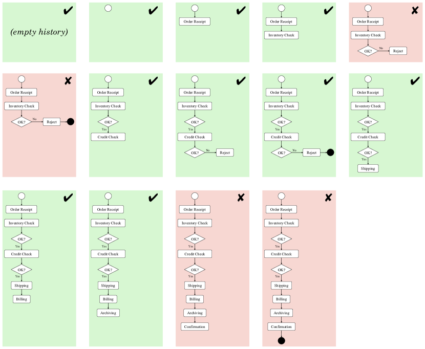
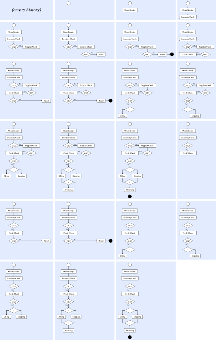
Appendix D Basic
D.1 Elaborations of
and
can be elaborated to a process that is weakly observationally bisimilar to , as follows:
(by the Delet, Creat, and React rules, is reflexive, and because is the identity process).
can be elaborated to a process that is weakly observationally bisimilar to , as follows:
(by definition of , and by the Delet, Creat, L-Par, R-Par, and React rules, is reflexive)
(by the Delet, Creat, L-Par, R-Par, and React rules, is reflexive)
(by the Delet, Creat, L-Par, R-Par, and React rules, is reflexive)
(by the Delet, Creat, L-Par, R-Par, and React rules, is reflexive)
(by the Delet, Creat, L-Par, R-Par, and React rules, is reflexive)
(by the Delet, Creat, R-Par, and React rules, is reflexive)
(by the commutativity and associativity of the parallel composition operator, and because is the identity process)
(, and by definition of ).
D.2 Models of Designs of Configuration 1
In this section, we model Designs 2, 3, and 4 (described in Section 3.3) of Configuration 1; Design 1 of the configuration is modelled in Section 6.3.
Let be a finite set of possible order identifiers.
Configuration 1 of the workflow is denoted by the process , where
This model applies to all four designs of Configuration 1.
The differences between the designs are represented by the differences in the definitions of each concurrent process of ,
particularly in the location of the recursively defined process.
In the model of Design 1, the recursively defined process is ,
which executes sequentially from , , and .
For Design 2, the recursively defined processes are the concurrent processes of , each of which executes concurrently from its containing process.
Thus, the recursive definition of is distributed between its concurrent processes.
For Design 3, the recursively defined process is , which executes concurrently from .
The model of Design 4 is a merge of the models of Designs 2 and 3 for each concurrent process of .
D.2.1 Model of Design 2
where
and denotes the Order Receipt task.
and denotes the Inventory Check subtask of Evaluation.
and denotes subtasks of Evaluation and Rejection.
and denotes the Credit Check subtask of Evaluation.
and denotes subtasks of Evaluation and Rejection.
and denotes the Shipping task, and denotes the Billing task.
and denotes the Archiving task.
and denotes the Confirmation task.
D.2.2 Model of Design 3
where
D.2.3 Model of Design 4
where
D.3 Lemma
Proof: assumes the lemma is and constructs a sequence of transitions of in the context that cannot be matched by in the same context to produce a contradiction.
The lemma is the lemma is (by definition of , and because the logic used is 2-valued).
If the lemma is
then
(by definition of )
implies each transition sequence of in any context
is matched by a corresponding transition sequence of in the same context up to transitions
such that the resulting process expressions are weakly observationally bisimilar in any context
(by definition of )
implies each transition sequence of in the context
is matched by a corresponding transition sequence of in the same context up to transitions
such that the resulting process expressions are weakly observationally bisimilar in the residual context
(by specialisation)
implies the transition sequence
(by the Sum and L-Par rules)
(by the Sum, React, and L-Par rules)
(by the Sum, React, and L-Par rules)
is matched by one or more of the following transition sequences (by specialisation)
(by the Sum and L-Par rules) or
(by the Sum, React, and L-Par rules) or
(by the Sum, React, and L-Par rules) or
(by the Sum, React, and L-Par rules) or
(by the Sum, React, and L-Par rules) or
(by the Sum, React, and L-Par rules) or
(by the Sum, React, and L-Par rules) or
(by the Sum, L-Par, and React rules) or
(by the Sum, L-Par, R-Par, and React rules) or
(by the Sum, L-Par, and React rules) or
(by the Sum, R-Par, and React rules) or
(by the Sum, React, and L-Par rules) or
(by the Sum, React, and R-Par rules) or
(by the Sum, L-Par, and React rules) or
(by the Sum, R-Par, and React rules) or
(by the Sum, L-Par, and React rules) or
(by the Sum, L-Par, and React rules) or
(by the Sum, R-Par, and React rules) or
(by the Sum, React, and L-Par rules) or
(by the Sum and React rules) or
(by the Sum and React rules) or
(by the Sum and React rules) or
(by the Sum and React rules) or
(by the Sum and React rules) or
(by the Sum and React rules).
That is,
in the context
(by the LTS rules) and
in the context (by the LTS rules)
where represents one of the processes elaborated above from such that
in the residual context
(by definition of , )
implies and both perform
in the context
(by the Sum and L-Par rules and by definition of ).
None of the processes elaborated above from performs (by the LTS rules)
implies does not perform in the context
(by specialisation; which is a contradiction).
Therefore, the lemma is not false
implies the lemma is true ( the lemma is the lemma is ). Q.E.D.
D.4 Corollary
Proof:
(by the syntax of )
implies
(by Lemma D.3). Q.E.D.