Control of Rayleigh-like waves in thick plate Willis metamaterials
Abstract
Recent advances in control of anthropic seismic sources in structured soil led us to explore interactions of elastic waves propagating in plates (with soil parameters) structured with concrete pillars buried in the soil. Pillars are m in diameter, m in depth and the plate is m in thickness. We study the frequency range to Hz, for which Rayleigh wave wavelengths are smaller than the plate thickness. This frequency range is compatible with frequency ranges of particular interest in earthquake engineering. It is demonstrated in this paper that two seismic cloaks’ configurations allow for an unprecedented flow of elastodynamic energy associated with Rayleigh surface waves. The first cloak design is inspired by some approximation of ideal cloaks’ parameters within the framework of thin plate theory. The second, more accomplished but more involved, cloak design is deduced from a geometric transform in the full Navier equations that preserves the symmetry of the elasticity tensor but leads to Willis’ equations, well approximated by a homogenization procedure, as corroborated by numerical simulations. The two cloaks’s designs are strikingly different, and the superior efficiency of the second type of cloak emphasizes the necessity for rigor in transposition of existing cloaks’s designs in thin plates to the geophysics setting. Importantly, we focus our attention on geometric transforms applied to thick plates, which is an intermediate case between thin plates and semi-infinite media, not studied previously. Cloaking efficiency (reduction of the disturbance of the wave wavefront and its amplitude behind an obstacle) and protection (reduction of the wave amplitude within the center of the cloak) are studied for ideal and approximated cloaks’ parameters. These results represent a preliminary step towards designs of seismic cloaks for surface Rayleigh waves propagating in sedimentary soils structured with concrete pillars.
pacs:
41.20.Jb,42.25.Bs,42.70.Qs,43.20.Bi,43.25.GfI Introduction
In a recent theoretical proposal diatta2014 , control of body waves was numerically demonstrated with a spherical shell consisting of an anisotropic heterogeneous elasticity tensor without the minor symmetries (what falls within the framework of so-called Cosserat media), and an heterogeneous (but isotropic) density. In diatta2014 , it was suggested that a simplified version of this elastodynamic cloak could be implemented to protect objects, nuclear waste or even large scale infrastructures buried deep down in the soil. However, achieving asymmetric elasticity tensors for instance via effective medium approaches remains a challenge. Indeed, the Cosserat theory cosserat of elasticity (or micropolar elasticity) incorporates a local rotation of points as well as the translation assumed in classical elasticity, and a couple stress (a torque per unit area) as well as the force stress (force per unit area). In the isotropic Cosserat solid or micropolar continuum, there are six elastic constants, in contrast to the classical elastic solid which is described by two constants. This makes Cosserat cloaks fairly challenging to engineer. In the present paper, we follow a different route towards seismic wave cloaking for surface Rayleigh waves, without resorting to Cosserat media. Before we move to the core material of this paper, we would like to first recall why soils structured at a meter scale might counteract deleterious action of certain types of seismic waves, what might seem at first glance fairly counter-intuitive.
More than a million earthquakes are recorded every year, by a worldwide system of earthquake detection stations, some of which are particularly devastating and cause human casualties, such as the earthquake of magnitude-6.2 that struck Italy on the 22nd of August 2016 at 01:36 GMT, km north-east of Rome, not far from L’Aquila, where a similar earthquake struck on the 9th of April 2009. The propagation velocity of the seismic waves depends on density and elasticity of the earth materials (clearly, it is much different in sedimentary soils and rocks). At the scale of an alluvial basin, such as in L’Aquila, seismic effects involve various phenomena, such as wave trapping, resonance of whole basin, propagation in heterogeneous media, and the generation of surface waves at the basin edge brule . As noted in eml2016 , wherein meter-scale inertial resonators were introduced to reflect surface and body seismic waves, due to the surface wave velocity in superficial and under-consolidated recent material (less than to m.s, wavelengths of surface waves induced by natural seismic sources or construction work activities are shorter than those of earthquake generated direct P (primary, i.e. longitudinal compressional) and S (secondary, i.e. transverse shear) waves (considering the - Hz frequency range), from a few meters to a few hundreds of meters. These are of similar length to that of buildings, therefore leading to potential building resonance phenomena in the case of earthquakes such as in L’Aquila. Other sources of soil vibrations one may wish to attenuate include traffic and construction works semblat , and screening methods have been proposed to achieve that woods ; banerjee .
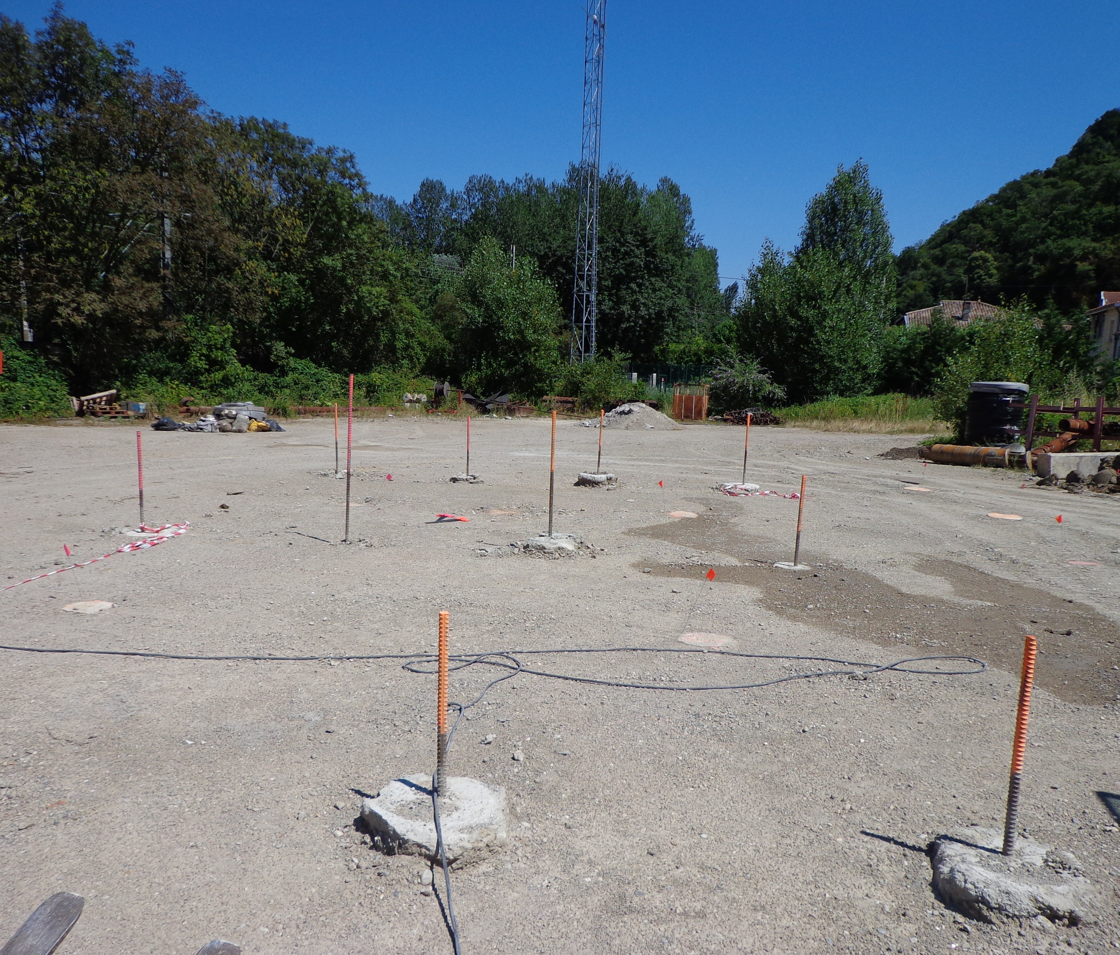
Interestingly, back in 1999 Rayleigh wave attenuation was theoretically and experimentally achieved in marble quarry with air holes displaying kHz stop bands meseguer and similar filtering effects in a microstructured piezoelectric for MHz till GHz surface waves sarah ; younes1 ; younes2 ; younes3 ; younes4 . In our previous work on control of surface Rayleigh waves in soils structured with borehole inclusions, we used so-called elastic stop bands which are frequency intervals for which waves are disallowed to propagate in an infinite periodic array through Bragg interferences (when the wave wavelength is on the order of the array pitch). With boreholes m in diameter, with a center to center spacing of m and the soil parameters on this field experiment prl2014 , this meant we had a stop partial band around Hz (for only one crystallographic direction). Three rows of boreholes were enough to reduce the energy of the signal by about per cent behind the seismic metamaterial. However, if one were to design a shield for the frequency interval to Hz, it would be necessary to scale up the array of boreholes by a factor of five to ten, which requires a lot of free space around the area, one wishes to protect. To overcome this obstacle, we now propose to use columns of concrete instead of boreholes, so as to achieve subwavelength control of Rayleigh surface waves. We show in figure 8 an example of such a structured soil, which was designed by civil engineers of the Menard company.
Importantly, the contrast between the soil and concrete column’s parameters makes it possible to achieve uncommon effective material parameters, such as with strong artificial anisotropy and dispersion, and even artificial inertia and viscosity that can be interpreted as rank-3 tensors in an effective Willis equation. This leads to a markedly enhanced control of surface Rayleigh wave trajectories compared to our earlier work prl2014 . Indeed, comparisons between numerical results demonstrate that one can achieve some cloaking of surface (Rayleigh-like) wave trajectories, where the wave field is almost unperturbed outside the seismic cloak, whereas it simultaneously nearly vanishes in its center. Bearing in mind that we use soil and concrete elastic parameters for the thick plate and pillars, and that we consider wave frequencies lower than hertz, we claim that our results represent a preliminary step towards implementation of seismic cloaks in civil engineering.
In this paper, we would like to present a novel approach for the design of seismic cloaks, which is based on the Willis-type equations, as proposed in the seminal paper by Milton, Briane and Willis milton2006 , which investigated form invariant governing equations in physics, notably coordinates transforms in Navier equations ensuring a transformed symmetric elasticity tensor. For the sake of simplicity in the numerical computations and physical discussions, we shall restrict ourselves to elastic waves in thick plates, rather than in semi-infinite media. Such a choice is in compliance with the fact that Rayleigh wave amplitudes decay exponentially (it vanishes within two wavelengths) with depth, becoming approximatively zero by the time a depth of two wavelengths has been reached. However, we consider wavelengths small compared to the plate’s thickness, hence surface waves are akin to Rayleigh, rather than Lamb, waves. Indeed, as noted in prl2014 , the elastic plate model already gives some interesting insight in the physics of seismic waves. The frequency of interest in earthquake engineering is governed by the frequencies of structures for the fundamental mode and the first harmonics. Typically, the fundamental period expressed in seconds, for N-story structure could be approximated by . For our numerical implementations, we have decided to focus on the range of to Hz corresponding to low-rise common building with only few storeys.
The plan of the paper is as follows: We first present some derivation of transformed Navier equations with a symmetric elasticity tensor, for thick plates. The obtained Willis equations are then simplified (removal of rank-3 tensors) and the illustrative case of a cloak with heterogeneous anisotropic Willis equations is numerically solved with finite elements implemented in the COMSOL commercial package. We then explain how one can approximate these anisotropic elastic parameters with an effective medium approach. The touchstone of our homogenization approach is that all tensors are symmetric. We finally propose two designs of soils structured with concrete pillars which are numerically validated with finite elements.
II Elastodynamic Willis Material, equations of motion
The propagation of elastic waves is governed by the Navier equations. Assuming time harmonic dependence, with as the angular wave frequency and the time variable, allows us to work directly in the spectral domain. Such dependence is assumed henceforth and suppressed, leading to
| (1) |
where is the density of the (possibly heterogeneous isotropic) elastic medium and is the three-component displacement field in a cylindrical coordinate basis . Also, is the rank-four (symmetric) elasticity tensor with components () and stands for the double contraction between tensors. For example, is the 2-tensor with components . Let us consider a coordinate change , where are stretched spherical coordinates. In general, this leads to a transformed equation milton2006 ; norris2011
| (2) |
or, in a more compact way
| (3) |
where , are 3-tensor fields, is the gradient in transformed coordinates and is a transformed displacement in stretched cylindrical coordinates. Note that the transformed stress is generally not symmetric. Note also that in general is a matrix field. In order to preserve the symmetry of the stress tensor, one assumes that is a multiple , of the Jacobian matrix of the transformation, where is a non-zero scalar, in which case (2), (3) are said to be Willis-type equations willis1981 ; milton2006 .
III Approximated cloaking with Willis material without 3-tensors
Following the proposal of Pendry et al. of an invisibility cloak via transformation optics pendry , we consider a specific geometric transformation, in cylindrical coordinates
| (6) |
with . Such a transformation blows the axis of a vertical solid cylinder of radius , into the cylinder while confining the whole solid cylinder into the following hollow cylinder of inner and outer radii and respectively.
In the sequel, we plug the transformation (6) into the Navier equations
| (7) |
to derive the corresponding transformed equations (2), (3). From here on, we drop (neglect) the 3-order tensors and D and hence use an approximate version of the Willis-like Equations. Note that in this case, obviously still has its minor and major symmetries, but is anisotropic and heterogeneous, with coefficients in cylindrical coordinates
| (8) |
The stretched density is now a tensor field of order 2, in particular, it is anisotropic and inhomogeneous. Namely, it has non-constant different eigenvalues and is diagonal in cylindrical coordinates with components as follows
| (9) |
Although all the (minor and major) symmetries of are preserved, the anisotropy in the azimuthal direction is infinite at the inner boundary of the cloak, as recedes to infinity as quickly as when approaches However and are of the same order and both tend to zero at the same rate at the inner boundary Meanwhile, at the same boundary, the off-diagonal components all become infinite at the rate , whereas tend to zero. One remarks in the meantime that, the eigenvalues and of the density in the and directions both vanish, whereas in the azimuthal direction becomes infinite at the inner boundary of the cloak. The material requirement for vanishing density along the vertical direction can be relaxed for Rayleigh waves, since their amplitude goes to zero within two wavelengths (this is fortunate as it means we won’t have to structure the soil in the vertical direction when we approximate the ideal cloak parameters through homogenization approach). However, variation of transverse anisotropic density (in the horizontal xy-plane) according to (9) is a strong requirement for a fully operational cloak.
III.1 Rayleigh-like waves in thick plates
In this paper, we apply the approximate Willis cloaking discussed above, to Rayleigh waves in particular in the framework of seismic metamaterials. Rayleigh waves, unlike Love waves, are surface waves that do not need a layer to guide them. The former surface waves exist in semi-infinite homogeneous isotropic media with a stress -free boundary. In our present work, we consider plates whose thickness is larger than the wavelength of the surface wave, which are akin to Rayleigh waves. When we make the geometric transform in the Navier equations, the stress-free boundary conditions also undergo the mapping. Hence one has to apply the transformation to the Navier Equations coupled with the stress-free boundary condition
| (12) |
with the (outward) normal at the points on the surface . In our case, the horizontal plane stands for the soil-air interface of the thick plate. In the resulting Willis-type equations discussed in the previous sections, the approximated technique is again applied coupled with
| (13) |
where is the normal at the transformed boundary.
III.2 Numerical implementation of Rayleigh-like waves in thick plates with soil parameters using Finite Element Method
Aiming at applications particularly in civil engineering such as seismic protection, we base the numerical model corresponding to the cloak described above on soil parameters. Namely, we use the Lamé coefficients Pa, Pa and density kg/m3. Although the approach developed here is general, we chose to concentrate our numerical tests on the range of to Hz corresponding to low-rise common building with only few storeys.
The cloak consists of a vertical cylindrical hollow region of height m, with an annulus-like basis of inner and outer radii m and m respectively and the axis as its main axis. It surrounds a homogeneous isotropic cylindrical domain of radius (the cloaked region) made of soil. Likewise, the cloak itself is located inside a cylindrical homogeneous isotropic medium (the ambient space) also made of soil and surrounded by a cylindrical shell of inner and outer radii m and m respectively, which is filled with an anisotropic heterogeneous absorptive medium acting as a (reflectionless) perfectly matched layer (PML). The top plane is a stress-free surface, which is the interface between the soil and the air.
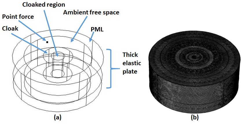
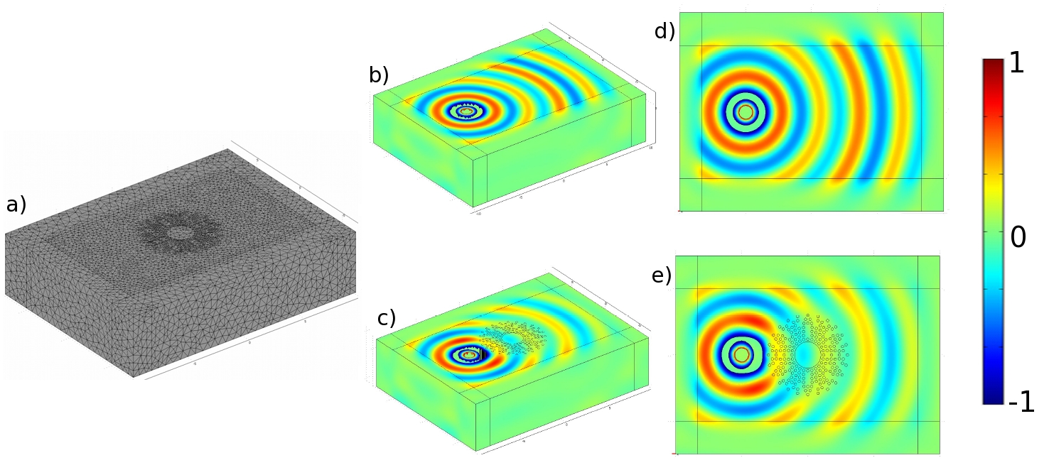
The implementation of this model in the finite element package COMSOL MULTIPHYSICS requires the use of Cartesian coordinates. Fortunately, of the spatially varying entries of the transformed elasticity tensor vanish identically. We mesh the computational domain using tetrahedral elements, triangular elements, edge elements and vertex elements, as shown in Fig. 1(b).
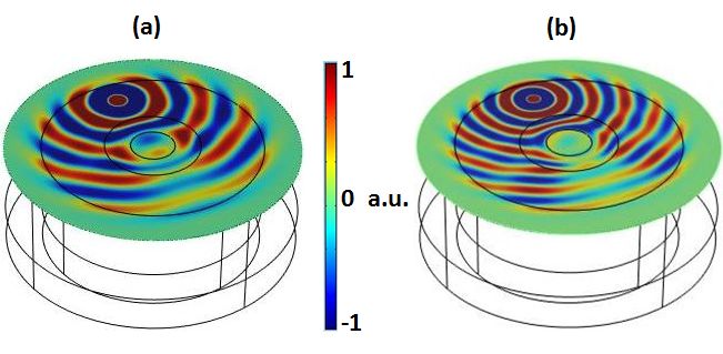
A point force located at , - that is, it lies on the soil-air free surface at a distance of meters from the axis of the cloaked region, - oriented along the direction generates a Rayleigh-like wave at frequency Hz (Fig 2 (A))– which corresponds to a wave wavelength m that is greater than half of the basin depth ( m), so this surface wave still behaves like a plate wave– and at frequency Hz (Fig 2 (B))– which corresponds to a wave wavelength m strictly lower than half of the basin depth– so it does not feel the bedrock. Following predictions in diatta2016 , one expects that some Rayleigh-like waves generated by specific frequencies of the source will create resonances (trapped modes) within the cloaked region as in Figure 2 (a), wherein a dipole mode can be observed (the inner cylinder wobbles) : This occurs at a countable set of eigenfrequencies corresponding to the problem of the Neumann (stress-free) cylindrical cavity in the center of the cloak, as we will investigate in section VI. At a source frequency away from the cavity trapped modes, one can clearly see that we achieve a good seismic protection (Fig. 2 (b)), see also Fig. 7 where a quantitative study is carried out in the frequency range Hz to Hz. Elastic parameters for a cloak with a Willis-like heterogeneous anisotropic transformed medium seem unachievable in practice with current civil engineering techniques. We therefore present in the sequel a homogenization route towards achievable Willis-like seismic cloaks.
At this stage, let us point out that an alternative route to control of Rayleigh waves consists in applying tools of conformal optics as proposed by Ulf Leonhardt leonhardt , that in the context of transformational elastodynamics lead to spatially varying isotropic elastic parameters andrea . Although this might seem an easier way towards cloaking, this requires structuring soil with pillars softer than soil, which is actually the opposite case to what we do in the sequel.
IV Homogenization approach for approximate Willis medium without rank-3 and rank-2 tensors
Our homogenization approach to achieve required rank-4 and rank-2 tensors proceeds in two steps. Firstly, we follow the proposal of Greenleaf and coworkers greenleaf2008 to apply the two-scale convergence method of G. Allaire and G. Nguetseng 2scale1 ; 2scale2 in the design of approximate multi-layered cloaks, we derive a set of effective parameters for a multi-layered elastic cloak, which is akin to homogenized parameters obtained by the G-convergence approach in jikov , except that these parameters remain dependent upon the macroscopic variable. We consider an alternation of concentric layers of respective elasticity tensors and and of respective densities and so that the overall elasticity tensor and density can be written
| (14) |
where is the position vector, and is its Euclidean norm and is the indicator function of the interval ( is typically the unit cell size along the direction of periodicity). The spatially varying tensor is periodic on and defines the periodicity (the thinner the layers, the smaller , the larger the number of layers). The governing equation reads:
| (15) |
When tends to zero, it is shown in jikov that the solution to the above Navier equation two-scale converges towards solution to the homogenized Navier equation:
| (16) |
with an effective (symmetric) elasticity tensor
where
| (17) |
and with the unit cell.
Moreover, the effective density reads as
| (18) |
One notes that the effective density is thus scalar valued and cannot achieve a rank-2 symmetric density tensor as required by the approximate Willis medium constituting the cloak, according to (9). Furthermore, it is suggested in diatta-kadic2016 that at least in some cases, in order for one to perform cloaking with an elastic material defined by a symmetric elasticity tensor, one might need that the material be also defined by an anisotropic density. Inspired by earlier work on locally resonant acoustic metamaterials for anisotropic effective density sashabook ; martinsson ; torrent1 ; milton2007 ; hfh ; torrent2 ; huang ; christensen2015 , we therefore add a second step in the homogenization process, that amounts to adding concrete bars in the soil.
As is well known using spring-mass approximations of locally resonant elastic metamaterials, a dynamic effective (diagonal) density tensor is given by christensen2015 :
| (19) |
which is a dynamic correction to (18) with the oscillator strengths of the resonances .
V Elastic thick plates structured with concrete columns for homogenized Willis medium without rank-3 tensors but anisotropic effective dynamic density
In this section we investigate the case of seismic cloaks which are a mitigation of cylindrical elastodynamic cloaks as proposed in brunapl for in-plane coupled shear and pressure waves (which unfortunately require Cosserat media) and thin plate cloaks prb2009 ; farhat2009 ; farhat2012 ; stenger2012 ; andrea1 for Lamb waves. Our case is indeed dedicated to Rayleigh like waves in thick plates. We do not claim that our cloaks work for body waves.
Bearing in mind that many authors have thus far achieved dynamic anisotropic density, see for instance torrent1 ; milton2007 ; torrent2 ; huang ; christensen2015 , symmetrized Willis cloaks are then achievable by classical homogenization approaches (getting rid of rank-3 tensors) with high contrast in material parameters for the artificial anisotropic density.
We would like to explore the propagation of elastodynamic waves in two types of cloaks that are in line with such a high-contrast homogenization, using the finite element method. The two cloaks are dedicated to seismic protection and could be achieved by manufacturing soil using concrete columns. Physical parameters are Pa, Pa and density kg/m3 for soil and Pa, Pa and density kg/m3 for concrete.
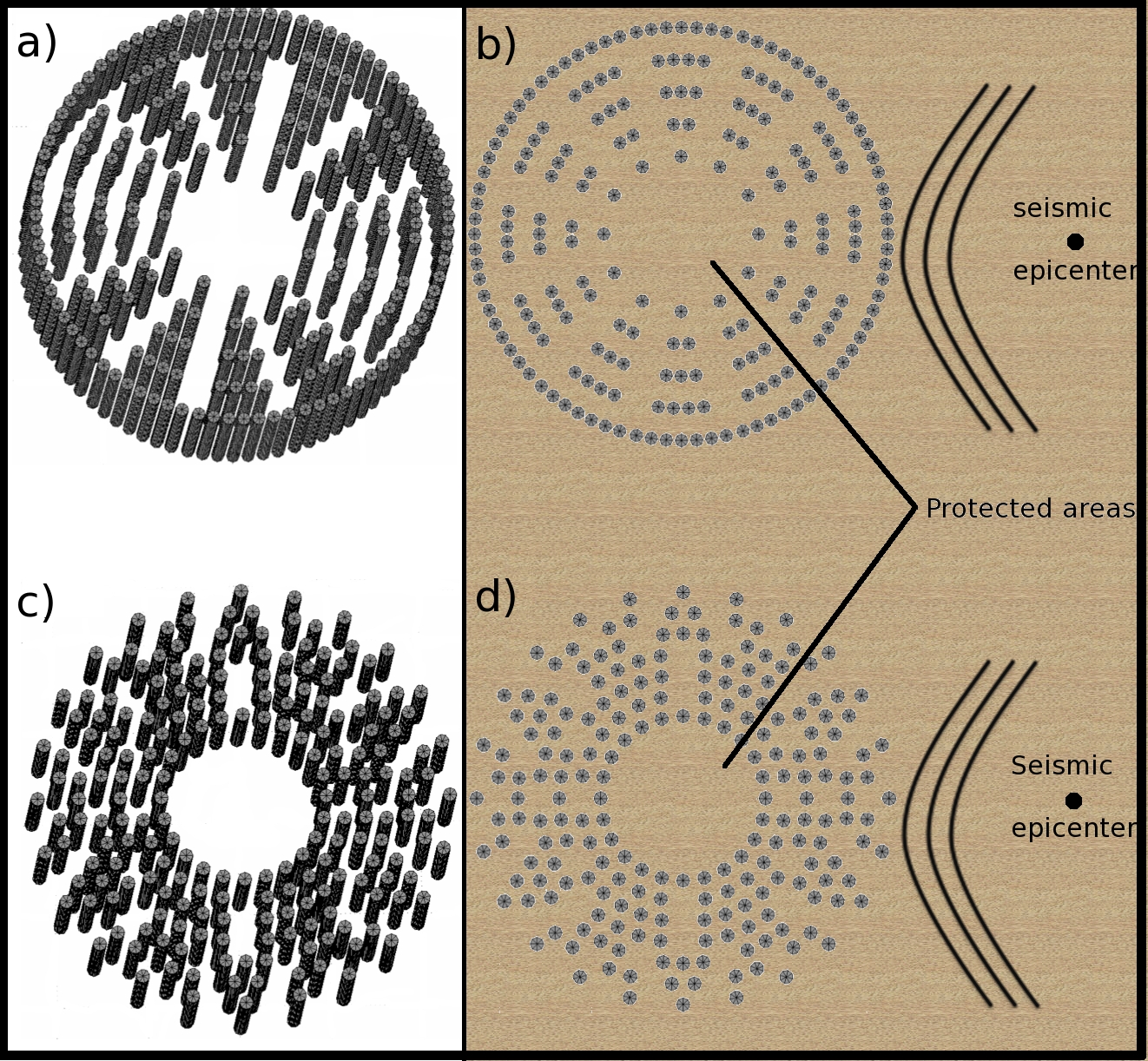
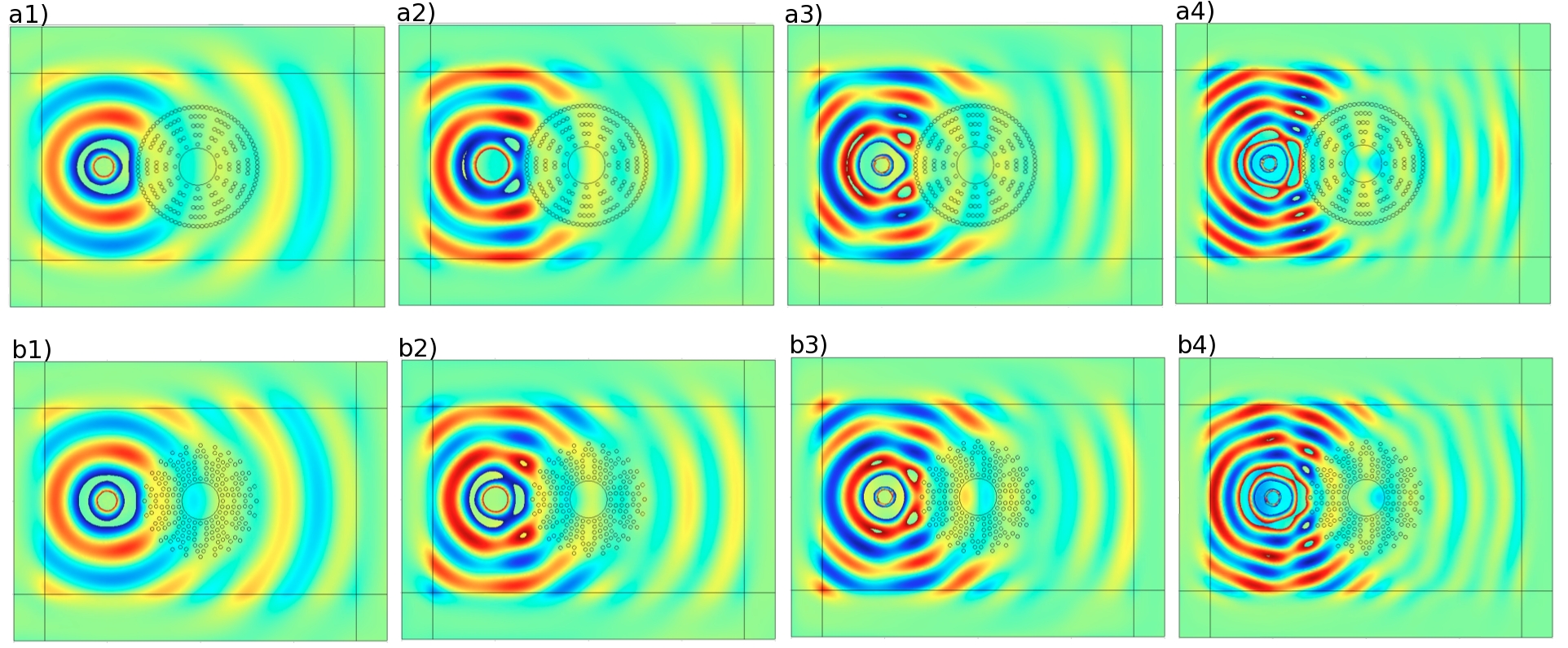
In order to prevent eventual reflections on the boundaries, Perfectly Matched Layers (PMLs) are applied to simulate the infinite extent of the elastic medium in the horizontal plane (note that we use so-called adaptative PMLs that work from high-frequencies down to the quasi-static limit, see diatta-kadic2016 ). A point source is placed atop a semi infinite medium representing the earthquake epicenter, which provoke a Rayleigh-like wave (a type of wave that can be harmful and detrimental for buildings). The outside and inside radii of the cloak measure m and m, respectively. The point source is located at m from the cloak center. Concrete columns are m in diameter and penetrate m in depth. Since we are interested in a frequency range greater than Hz, the soil depth is set to m (note that at Hz Rayleigh waves have a wavelength of m) and we apply free traction boundary condition to the bottom). We have checked that such a condition gives comparable results to those that are obtained if the bedrock is identified m beneath soil. Indeed, potential reflection occur in both cases due to impedance mismatch. We deliberately consider such configuration as it seems more realistic than using PMLs that would model an infinitely deep, unstratified, soil. Concrete columns are arranged in a way that the effective density decreases as we move towards the center of the cloak. The designs of structured cloaks are optimized in order to achieve a reasonable balance between approximation of ideal cloak parameters according to effective equations of section IV and what can be implemented in practice with civil engineering technology at hand (i.e. various distributions of concrete columns of various diameter and length have been numerically tested). Indeed, the range of frequencies from Hz to Hz corresponds to wavelengths much larger than the columns’s diameters ( subwavelength inclusions underpins homogenization theory) and small enough compared to the basin depth to investigate Rayleigh waves rather than plate waves. Since the first cloak design, which we propose is deduced from elements of thin plate theory, we also look at the frequencies from Hz to Hz, which correspond to a transition between plate and Rayleigh waves. Indeed, the frequency range of interest for civil engineering is from to Hz, and it is interesting to check whether or not our cloaks’s designs work beyond their ’legitimate’ range of frequencies.
V.1 A first cloak design based on thin plate approximation
Nevertheless, we notice that the distribution of inclusions in Fig. 3(a)-(b) is coherent with the formula of the density of an elastic cloak previously reported by prb2009 in the limit of thin plates (so-called Kirchhoff-Love theory) and reads:
| (20) |
with . However, this step doesn’t achieve the required effective anisotropy, and should be only valid for plate waves (which are akin to Rayleigh waves in the limit of thick plate not covered by Kirchhoff-Love theory).
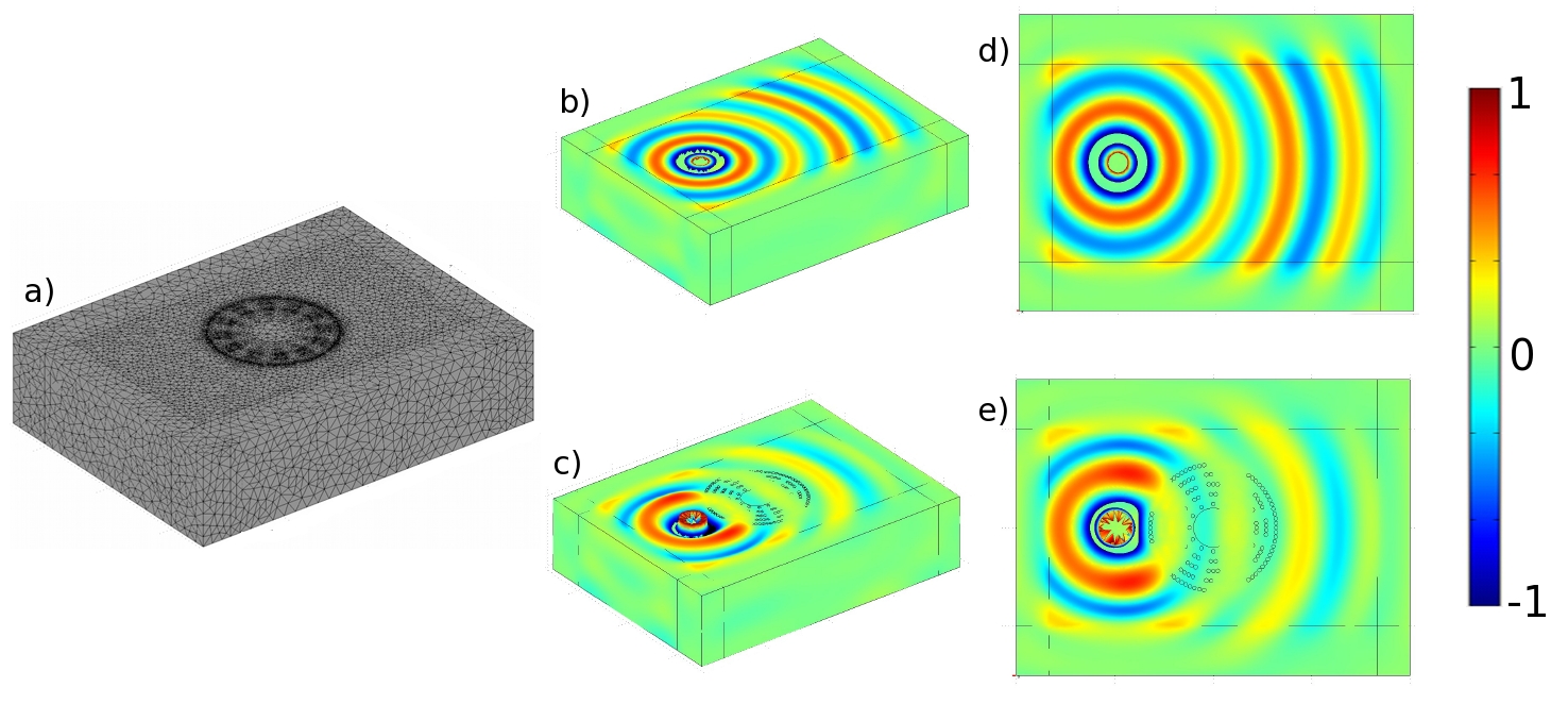
We depict in Fig. 4 the real part of the out of plane displacement field in 3D and top view representations at Hz. It is observed that more than 50% of the field is suppressed at the center of the cloak (zone of protection) but recovered at its exit. The acceleration phenomenon is also noticed within the cloak area due to the higher effective Young’s modulus. However, when we compute the cloak efficiency for protection throughout the frequency range , we find that protection is merely 40% on average, see Fig. 7(b). This is quite a dramatic reduction of protection compared with the ideal cloak, which has 70% of protection on average, see Fig. 7(a).
The cloak is efficient between Hz and Hz as it transpires in Fig. 7. It is worth noting that the lower limit (3 Hz) is connected to the basin depth (in which case waves transition from Rayeligh to Lamb) and the upper limit (10 Hz) to the diameter of the columns. The smaller the diameter the higher the upper frequency limit. Indeed the phenomenon is constrained by the diffraction that might be caused by the columns as can be observed in Fig. 6(a4).
V.2 A second cloak design based on approximate Willis equations in thick plates
We now make use of the much more involved transformational (section III) and effective (section IV) models for Willis equations in thick plates. In the configuration of cloak of type II, the inward effective anisotropy increases. This is accompanied by an undesirable reduction of the effective density the outer boundary of the cloak. This can be explained as the following: the concrete columns are arranged by bunch of clusters with one element over the first layer, two elements over the second and so forth up to the sixth layer. The seventh and last layer is isotropic and could be seen as a seismic shield. We depict in Fig. 4 the real part of the out of plane displacement field in 3D and top view representations at Hz. For the sake of comparison, the free medium is also represented. We can notice that unlike the first configuration, there is much less reflection at the cloak entrance (due to the smooth mismatch of impedance), a quasi perfect restitution of the field at the exit and a comparable protection inside the cloak (almost 50 of the energy is suppressed on average in the frequency interval as can be seen in Fig. 7(c)). However, it is noticed in Fig. 7(a), that some resonances occur in the ideal cloak, and similar effects occur with cloak of type II (notably around Hz) in Fig. 7(c).
V.3 First conclusions on cloaks of type I and II
As can be seen in Fig. 6, cloak of type II performs clearly better than cloak of type I for both protection and invisibility. This can be attributed to the fact that the latter has been designed using transformed equations farhat2012 , and homogenization techniques farhat2009 in the context of thin plate theory. Kirchhoff-Love theory is an approach well suited for control of Lamb waves as experimentally validated in stenger2012 . However, such a limit theory is not legitimate in our case of thick plates, at least from a mathematical standpoint (the Rayleigh-like wave wavelength should be at least ten times smaller than the plate thickness to satisfy the hypothesis of thin plate, which is clearly not the case in our study). Interestingly, both cloaks of type I and II display resonances similarly to ideal cloak, see Fig. 7 (with a better match between ideal cloak and cloak of type II). We believe such unwanted resonances require a specific analysis of its own, as addressed in the next section. It is interesting to note that the level of protection displayed by our three cloaks (both ideal cloak and cloaks of types I and II) is lower than what is achieved through shielding effects via low frequency stop bands in miniaci16 . Although we consider the same frequency range as in miniaci16 , in our case we detour Rayleigh waves around the protected area, and there is little backscattered wave, so the protection mechanism is radically different.
VI Estimate of local resonances inside the seismic cloak
Following diatta2016 , where the case of Cosserat spherical cloaks is dealt with, in this section we investigate the origin of the resonances in the ideal cylindrical cloak by simplifying the governing Navier equations into a simple spring-mass model approximation leading to a transcendental equation. To do so, we assume that the plate thickness goes to infinity, in which case one can decouple the Navier equations as a vector problem for in-plane shear and pressure waves and a scalar out-of-plane problem for the vertical displacement . By doing so, we do not exactly address the problem of the Rayleigh waves, but this will nonetheless give us a reasonable estimate of the resonances, as we shall see. Because of the symmetry of the cloak, one can assume the out-of-plane displacement has a form , solution of the scalar Helmholtz equation
| (21) |
where , and . Actually, (21) can be written as a Bessel equation so it has a general solution, which is expressed in terms of cylindrical Bessel functions of first and second kinds (already derived in a different context in guenneau2010 ):
| (22) |
Then, assuming that and , we find that the eigenfrequency should satisfy the following equation
| (23) |
which gives the frequency estimate Hz since the first zero of is . This frequency estimate is in good agreement with the moderate elastic field enhancement shown in Fig. 7 around Hz. The frequency estimate for the second resonance is Hz since the second zero of is and this is also in qualitatively good agreement with the second peak in Fig. 7 around Hz. In fact, the predicted frequencies are overestimated since they are associated with out-of-plane shear waves, that propagate faster than Rayleigh waves.

VII Concluding remarks
In this article, we have conclusively shown that transformed Navier equations of the Willis type with a symmetric transformed elasticity tensor, allows for approximate cloak’s designs getting rid of the rank-3 transformed tensors unveiled in milton2006 . A further approximation consists in structuring soil with buried concrete pillars judiciously placed (note that this is the opposite case to what is proposed in andrea , wherein soil was structured with softer columns). This is done and finite element computations confirm the cloaking efficiency (invisibility and protection) for two types of large scale seismic cloaks within a soft elastic plate (with soil parameters) m deep reinforced with judiciously placed columns of concrete m long and m in diameter. Indeed, the two designs which we propose allow one to considerably reduce the elastic field vibrations in the center of the cloak with virtually no disturbance of the wave field outside the cloak. The protection could be further improved using the concept of mixed cloak diatta2016 , which amounts to adding a PML layer at the inner boundary of the cloak, in essence some absorptive anisotropic medium. Of course, alternative routes exist to seismic wave protection, and we would like to mention very promising designs of seismic metamaterials in the tracks of Ménard’s 2012 field test experiment in Grenoble prl2014 , notably so-called seismic waveguides kim2012 , but also large scale isochronous mechanical oscillators finochhio14 , inertial resonators krodel15 ; achaoui2015 ; eml2016 and auxetic-like foundations allowing for low frequency stop bands. Actually, in miniaci16 , numerical analysis of both surface and guided waves has been performed in miscellaneous large scale phononic crystals and metamaterials, with soil dissipation effects in viscoelastic media. Protection has been shown for frequency ranges associated with low frequency stop bands below Hz. Such design of seismic shields could be combined with seismic cloaks to offer a wave protection for both surface and bulk waves which does not have adverse effects for the surrounding environment. Speaking of which the idea of forest of trees for seismic wave mitigation remains the most environmental friendly proposal colombi , although it has been observed thus far that wave protection is achieved beyond the to Hz frequency range of interest for civil engineers.
We would like to add that our results could be translated into geophysics upon use of time domain computations. It would be also important to study the effect of viscoelasticity on the elastic wave propagation (in a way similar to what was done in miniaci16 ), which can be done with comsol multiphysics. Finally, some implementation of the seismic cloak with subsequent field test is in progress with the Ménard company. We show in Figure 8 a typical field test experiment by the Ménard company that could serve as a basis for the validation of our concept of seismic cloak, although this requires scaling down the diameter of inclusions of our study from m to m, as well as taking into account other constraints on minimum distance between inclusions, field topography etc. New designs of seismic cloaks are therefore underway to find a good compromise between cloak efficiency and feasibility in practice.
Acknowledgments
The authors would like to thank the anonymous reviewer for insightful remarks. A.D., Y.A. and S.G. acknowledge European funding through ERC Starting Grant ANAMORPHISM.
References
- (1) A. Diatta and S. Guenneau, ’Controlling solid elastic waves with spherical cloaks’, Appl. Phys. Lett. 105, 021901 (2014).
- (2) E. Cosserat, F. Cosserat, ’Theory of deformable bodies’, Scientific Library A. Hermann and Sons, Paris (1909).
- (3) S. Brûlé and E. Javelaud, ’Could deep soil densification impact the seismic site effect?,’ in Proceedings of the 9th Annual International Conference on Urban Earthquake Engineering (Tokyo Tech CUEE, Tokyo,2012), 497-501 (2012).
- (4) Y. Achaoui, B. Ungureanu, S. Enoch, S. Brûlé, S. Guenneau, ’Seismic waves damping with arrays of inertial resonators,’ Ext. Mech. Lett. (2016) (http://dx.doi.org/10.1016/j.eml.2016.02.004).
- (5) J.F. Semblat and A. Pecker, ’Waves and vibrations in soils: earthquakes, traffic, shocks, construction works’, IUSS Press, Pavia (2009).
- (6) R.D. Woods, Screening of surface waves in soils, Tech. Rep. IP-804, University of Michigan (1968).
- (7) P.K. Banerjee, S. Ahmad and K. Chen ’Advanced application of BEM to wave barriers in multi-layered three-dimensional soil media,’ Earthquake Eng. and Structural Dynamics 16, 1041-1060 (1988).
- (8) F. Meseguer, M. Holgado, D. Caballero, N. Benaches, J. Sanchez-Dehesa, C. Lopez, and J. Llinares, ’Rayleigh-wave attenuation by a semi-infinite two-dimensional elastic-band-gap crystal,’ Phys. Rev. B 59, 12169 (1999).
- (9) S. Benchabane, O. Gaiffe, G. Ulliac, R. Salut, Y. Achaoui and V. Laude, ’Observation of surface-guided waves in holey hypersonic phononic crystal,’ Appl. Phys. Lett. 98 (17), 171908 (2011).
- (10) Y. Achaoui, A. Khelif, S. Benchabane, L. Robert and V. Laude, ’Experimental observation of locally-resonant and Bragg band gaps for surface guided waves in a phononic crystal of pillars,’ Phys. Rev. B 83 (10), 104201 (2011)
- (11) A. Khelif, Y. Achaoui, S. Benchabane, V. Laude, B. Aoubiza, ’Locally resonant surface acoustic wave band gaps in a two-dimensional phononic crystal of pillars on a surface,’ Phys. Rev. B 81 (21), 214303 (2010).
- (12) Y. Achaoui, A. Khelif, S. Benchabane, V. Laude, ’Polarization state and level repulsion in two-dimensional phononic crystals and waveguides in the presence of material anisotropy,’ J. Phys. D: Appl. Phys. 43, 185401 (2010).
- (13) A. Khelif, Y. Achaoui and B. Aoubiza, ’Surface acoustic waves in pillars-based two-dimensional phononic structures with different lattice symmetries,’ Journal of Applied Physics 112 (3), 033511 (2012).
- (14) S. Brûlé, E. Javelaud, S. Enoch and S. Guenneau, ’Experiments on seismic metamaterials: Molding surface waves,’ Phys. Rev. Lett., 112 (13), 133901 (2014).
- (15) G.W. Milton, M. Briane, and J.R. Willis, ’On cloaking for elasticity and physical equations with a transformation invariant form,’ New J. Phys. 8, 248 (2006).
- (16) A.N. Norris and A.L. Shuvalov, ’Elastic cloaking theory,’ Wave Motion 48, 525-538 (2011).
- (17) J.R. Willis, ’Variational principles for dynamic problems for inhomogeneous elastic media,’ Wave Motion 3, 1-11 (1981).
- (18) J.B. Pendry, D. Schurig and D.R. Smith, ’Controlling Electromagnetic Fields,’ Science 312 1780 (2006).
- (19) A. Diatta, M. Kadic, M. Wegener, S. Guenneau, ’Scattering problems in elastodynamics,’ Phys. Rev. B 94, 100105(R) (2016).
- (20) U. Leonhardt, ’Optical Conformal Mapping,’ Science 312, 1777 ( 2006).
- (21) A. Colombi, S. Guenneau, P. Roux, R.V. Craster, ’Transformation seismology: composite soil lenses for steering surface elastic Rayleigh waves,’ Scientific reports 6, 25320 (2016).
- (22) Greenleaf, A., Kurylev, Y., Lassas, M. and Uhlmann, G. ’Isotropic transformation optics: approximate acoustic and quantum cloaking,’ New J. Phys. 10, 115024 (2008).
- (23) Nguetseng, G. A general convergence result for a functional related to the theory of homogenization. SIAM J. Math. Anal. 20, 608–623 (1989).
- (24) Allaire, G. Homogenization and two-scale convergence. SIAM J. Math. Anal. 23, 1482-1518 (1992).
- (25) V.V. Jikov, S.M. Kozlov and O.A. Oleinik, Homogenization of Differential Operators and Integral Functionals, Springer-Verlag Berlin Heidelberg (1994).
- (26) A. Diatta and S. Guenneau, ’Elastodynamic cloaking and field enhancement for soft spheres,’ J. Phys. D: Appl. Phys. 49, 445101 (2016)
- (27) A. Greenleaf, Y. Kurylev, M. Lassas, G. Uhlmann, ’Approximate quantum cloaking and almost trapped states,’ Phys. Rev. Lett. 101, 220404 (2008)
- (28) V. Kozlov, V.G. Mazya, A.B. Movchan, ’Asymptotic analysis of fields in multi-structures,’ Oxford University Press (1999)
- (29) P.G. Martinsson, A.B. Movchan, ’Vibrations of lattice structures and phononic band gaps’, The Quarterly Journal of Mechanics and Applied Mathematics 56 (1), 45-64 (2003).
- (30) D. Torrent, A. Hakansson, F. Cervera, Sanchez-Dehesa, ’Homogenization of two-dimensional clusters of rigid rods in air,’ Phys. Rev. Lett. 96, 204302 (2006).
- (31) G.W. Milton, ’New metamaterials with macroscopic behavior outside that of continuum elastodynamics,’ New Journal of Physics 9, 359 (2007).
- (32) D. Torrent, J.S. Dehesa, ’Anisotropic mass density by two-dimensional acoustic metamaterials,’ New J. Phys. 10, 023004 (2008).
- (33) R. V. Craster, J. Kaplunov, A. V. Pichugin, ’High-frequency homogenization for periodic media,’ Proc. Roy. Soc. Lond. A 466, 2341-2362 (2010).
- (34) H.H. Huang, C.T. Sun, ’Locally resonant acoustic metamaterials with 2D anisotropic effective mass density ’, Philosophical Magazine 91, 981 (2011).
- (35) J. Christensen, M. Kadic, O. Kraft and M. Wegener, ’Vibrant times for mechanical metamaterials’ Mrs Communications 5, 453-462 (2015) Science 314, 977-980 (2006).
- (36) M. Brun, S. Guenneau and A.B. Movchan, ’Achieving control of in-plane elastic waves,’ Appl. Phys. Lett. 94, 061903 (2009).
- (37) A.N. Norris and W.J.Parnell, Hyperelastic cloaking theory: Transformation elasticity with prestressed solids, Proc. R. Soc. Lond. Ser. A, 468 (2146), 2881-2903 (2012).
- (38) W.J. Parnell, Nonlinear pre-stress for cloaking from antiplane elastic waves, Proc. R. Soc. Lond. Ser. A 468, no. 2138, 563-580 (2012).
- (39) T. Bückmann, M. Thiel, M. Kadic, R. Schittny, M. Wegener, An elasto-mechanical unfeelability cloak made of pentamode metamaterials Nature communications 5, 4130 (2014).
- (40) M. Farhat, S. Guenneau, S. Enoch and A.B. Movchan, ’Cloaking bending waves propagating in thin elastic plates,’ Phys. Rev. B 79, 033102 (2009).
- (41) M. Farhat, S. Guenneau and S. Enoch, ’Ultrabroadband Elastic Cloaking in Thin Plates,’ Phys. Rev. Lett. 103, 024301 (2009).
- (42) M. Farhat, S. Guenneau and S. Enoch, ’Broadband cloaking of bending waves via homogenization of multiply perforated radially symmetric and isotropic thin elastic plates,’ Phys. Rev. B 85, 020301 R (2012).
- (43) N. Stenger, M. Wilhelm and M. Wegener, ’Experiments on elastic cloaking in thin plates,’ Phys. Rev. Lett. 108, 014301 (2012).
- (44) A. Colombi, P. Roux, S. Guenneau and M. Rupin, ’Directional cloaking of flexural waves in a plate with a locally resonant metamaterial,’ J. Acoust. Soc. Am. 137 (4), 1783-1789 (2015).
- (45) S. Guenneau, A.B. Movchan, F. Zolla, N.V. Movchan and A. Nicolet, ’Acoustic band gaps in arrays of neutral inclusions’, Journal of Computational and Applied Mathematics 234 (6), 1962-1969 (2010).
- (46) S.H. Kim and M.P. Das, ’Seismic Waveguide of Metamaterials,’ Mod. Phys. Lett. B 26, 1250105 (2012).
- (47) G. Finocchio, O. Casablanca, G. Ricciardi, U. Alibrandi, F. Garesci, M. Chiappini and B. Azzerboni ’Seismic metamaterials based on isochronous mechanical oscillators’ Appl. Phys. Lett. 104, 191903 (2014).
- (48) S. Krodel, N. Thome, and C. Daraio, ’Wide band-gap seismic metastructures,’ Extreme Mech. Lett. 4, 111-117 (2015).
- (49) Y. Achaoui, A. Diatta and S. Guenneau, ’Steering in-plane shear waves with inertial resonators in platonic crystals,’ Applied Physics Letters 106, 223502 (2015).
- (50) B. Ungureanu, Y. Achaoui, S. Enoch, S. Brule and S. Guenneau, ’Auxetic-like metamaterials as novel earthquake protections,’ EPJ. Applied Metamaterials 2, 17 (2016).
- (51) M. Miniaci, A. Krushynska, F. Bosia and N.M. Pugno ’Large scale mechanical metamaterials as seismic shields’, New Journal of Physics 18 (8), 083041 (2016).
- (52) A. Colombi, P. Roux, S. Guenneau, P. Gueguen and R.V. Craster, ’Forests as a natural seismic metamaterial: Rayleigh wave bandgaps induced by local resonances,’ Scientific reports 6, 19238 (2016).