The Newtonian mechanics of a Vibrot
Abstract
A mechanical model was developed to describe the behaviour of a device able to transform vibrations into rotations, named Vibrot. The theoretical model, developed in the newtonian formulation of mechanics, was able to reproduce qualitatively all the experimental results existing in the literature, and quantitatively some of them.
pacs:
45.20.D, 45.40.-f, 83.10FfI Introduction
Devices able to transform rotational energy into kinetic energy along the rotation axis have been very used for ages. Archimedes of Syracuse is credited with the invention of one of these devices, nowadays known as “Archimedes’s screw”, whose basic working principle is still used Screw0 ; Screw1 ; Screw2 . This kind of phenomenon have been well studied because of its direct implications in the industry, but what about the inverse phenomenon? The mysterious rotation of the statue of Neb-Senu, Statue , attracted the attention of several believers who explained it by formulating fanciful hypothesis. Nevertheless, the physicist Brian Cox formulated a more realistic one, where the vibrations produced by the steps of the visitors induced a rotation on the statue, Statue .
In order to unravel the working principle behind this phenomenon we will focus our attention in a simple device named Vibrot (vibration to rotation). A complete experimental description of a Vibrot as the one we aim to describe theoretically, may be found in Altshuler .
II The model
A Vibrot as the one designed by Altshuler et al. in Altshuler , is shown in Fig. 1a). We model a Vibrot as a head resting on three legs. The head consists in an homogeneous cylinder of radius mm and height mm. Each of the legs is made by a spring of equilibrium length mm and elastic constant N/m. The upper side of the springs are attached to the Vibrot’s body at a distance mm from the center of the cylinder’s bottom. A light rod freely slides inside each spring, and touches the ground through a flat disk. The three legs are axially symmetric relative to the bottom base, and are inclined relative to the vertical (see Fig. 1b)).
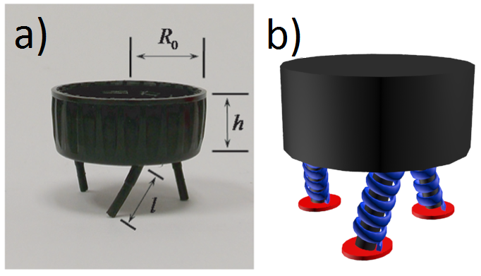
The vibrations of the platform used in Altshuler , can be introduced by means of an acrylic surface that vibrates sinusoidally in the vertical direction (i.e. along the gravity), with a frequency and amplitude . Our reference system was taken on the vibrating surface, so it is an accelerated framework. In order to describe the temporal evolution of the Vibrot we use the following coordinates:
-
•
: axis perpendicular to the base of the cylinder passing through its center.
-
•
: rotation angle of any point located in the cylinder’s base.
We first describe the forces acting along the z-axis. The gravity force points downwards, where is the Vibrot’s mass, and m/s2 is the acceleration of the gravity. When the springs are compressed a length , an elastic force is applied upwards. That happens when the distance between the base of the cylinder and the ground is smaller than . Otherwise the Vibrot is in its “flying phase” and , while springs keep their equilibrium length. As a consequence of taking an accelerated reference system we also have an inertial force, , where is the dimensionless acceleration and the angular velocity.
It is important to take into account, that every time the Vibrot collides with the platform, part of its kinetic energy is dissipated as heat and, like there is not previous models of a Vibrot, we will assume it happens due to a viscous friction. Strictly, this viscous force regards also the interaction between the Vibrot and the surrounding air, but this contribution can be neglected (the change in the kinetic energy by “air-friction” is much less than by “platform-friction”), so we assume that the viscous friction only mimics the collision between the Vibrot and the acrylic surface. Then, in the z-axis there is also a viscous force , where the parameter will be determined from the experimental data.
If we define the variable , the viscous and elastic forces can be written as
| (1) |
| (2) |
As we mentioned before, the elastic force only acts when the Vibrot is touching the platform (). To introduce this information we can use the Heaviside function, . Then, the elastic force is . Henceforth we will discuss the motion in the z-axis by means of the variable . We will also define , where is the rotation frequency.
So, the differential equation describing the vertical motion of the Vibrot is
| (3) |
In order to obtain the equation that describes the rotation of the Vibrot, we will pay attention to the momentum of the forces exerted on the cylinder. When the elastic force is acting, it has a component on the plane of the base of the cylinder, which has associated an absolute torque, , given by
| (4) |
Both the torque and the elastic force are only different from zero when . Furthermore, once the Vibrot touches the platform, a kinetic friction force begins to act, but quickly transforms itself into static. Modelling this force is also complicated, but we propose the following hypothesis: once the Vibrot collides with the vibrating membrane, the torque mentioned before changes its sign, and remains this way until it reaches the minimum, where it comes back to be positive. Moreover, as the static force cannot move the device backwards, we will assume the angular velocity to be non-negative. Also, we include a dynamic friction associated to the torque, , given by Eq. (5), where was taken as average normal force the ones in the position of equilibrium of the springs.
| (5) |
The friction coefficient was taken as, , which is the very close to the one between acrylic and caoutchouc. In order to avoid that the legs of the Vibrot slide backwards, the relation , must be fulfilled all the time. Note that if the friction coefficient is null, wherewith the Vibrot couldn’t rotate and due to the external torque vanishes while the angular momentum conserves, then the rotation frequency remains with the initial value, i.e. .
The differential equation that describes the temporal evolution of the rotation angle, is
| (6) | |||||
In this equation, represent the sign function, and we used as the moment of inertia of the Vibrot, (Moment of inertia of a cylinder). Equations (3) and (6) describe the temporal evolution of the device. We will solve them assuming that the Vibrot is at rest when , so the initial conditions are:
| (7) |
III Results
Solving analytically the system of differential equations (3) and (6) is a little complicated in spite of having the first equation disengaged. So, we have to solve it numerically. However, we can reach some analytical results, as follows.
In our model, the Vibrot does not rotate if the legs are touching the ground. So, if is negative, the Vibrot will not rotate, and it is possible to determine the threshold dimensionless acceleration , below which there is no rotation. In order to do that, the equation (3) is solved for , resulting the equation of a forced oscillator plus a constant. Then if the solution for a long time () is negative, the Vibrot will not rotate. For long times, the solution that prevails is:
| (8) |
where
| (9) |
By imposing and in Eq. (8), it is possible to obtain as:
| (10) |
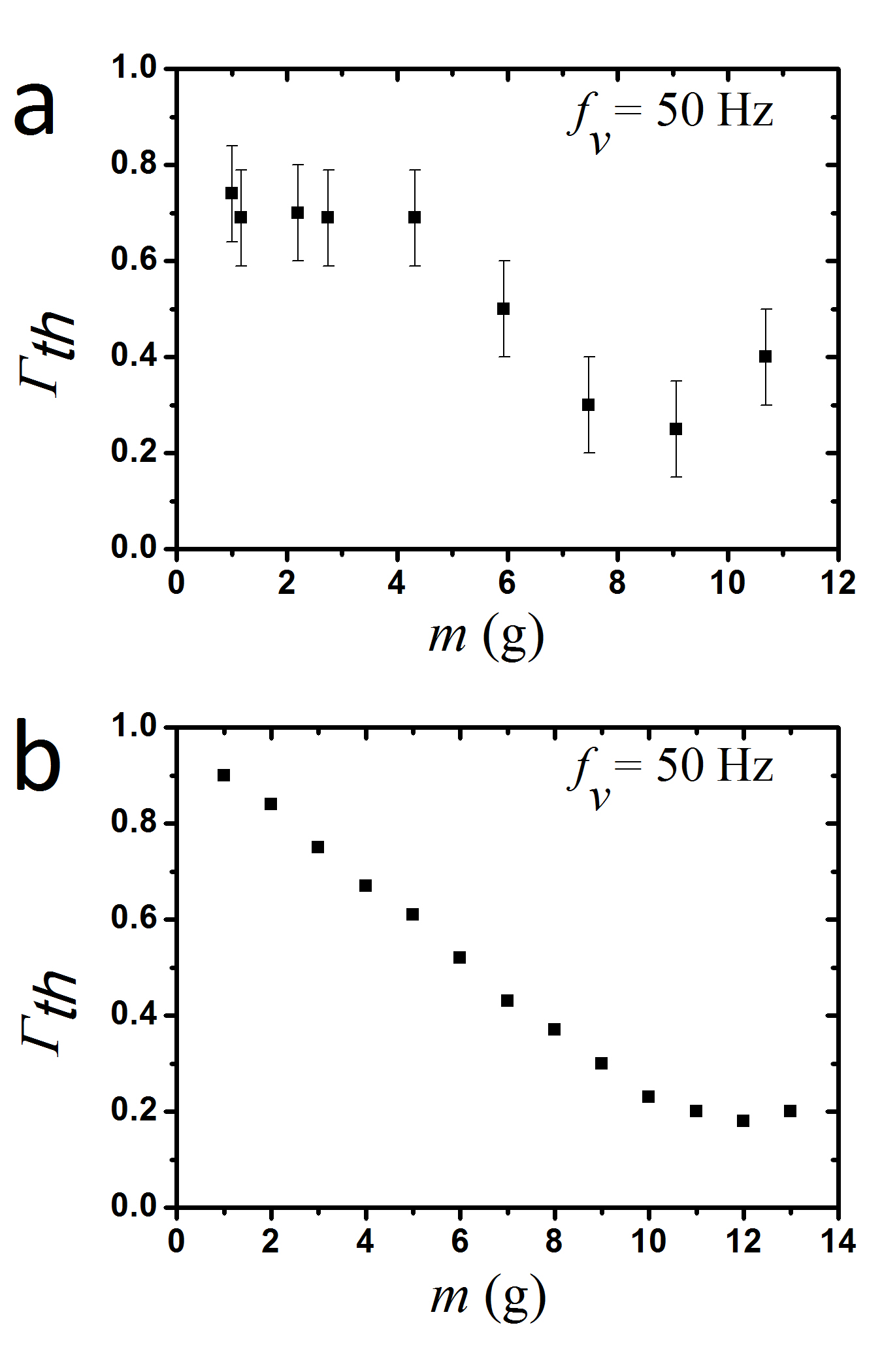
Using in Eq. (10) the expression , we obtain the dependency with the mass of . Fig. 2 shows the experimental result for vs. , reported in Altshuler as well as the one obtained here using Eq. (10).
In Fig. 2 we can see the resonance effect in both graphs. The model’s results are slightly right-shifted in a value on the order of g, a consequence of the choice of the parameters and . Here, it is important to remark the almost perfect coincidence between the numerical results and the ones obtained using Eq. (10).
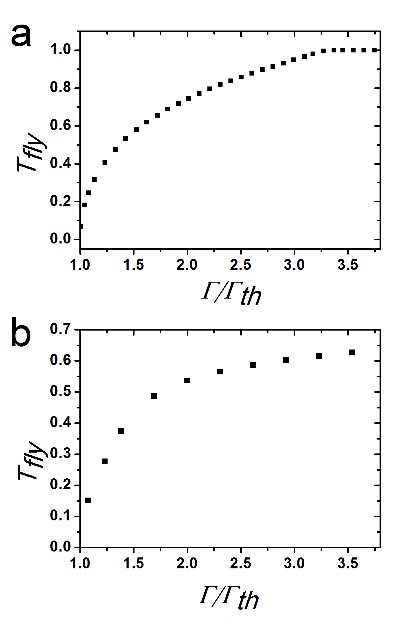
We also obtained an approximation for the fly time, , using the following expression:
| (11) |
where is the n-th zero of , (). We can see the fly time as a function of the normalized dimensionless acceleration () in Fig. 3. This figure shows that both graphs have the same behaviour, although we may say that the model underestimates the fly time.
Once solved numerically the system of differential equation, (3), (6) with boundary conditions given by (7), it is possible to obtain the behaviour of further magnitudes, like the rotation frequency as a function of other parameters. Experimentally, the rotation frequency is computed as the average value of the function: , but inasmuch as this function is not constant, we calculated the rotation frequency as:
| (12) |
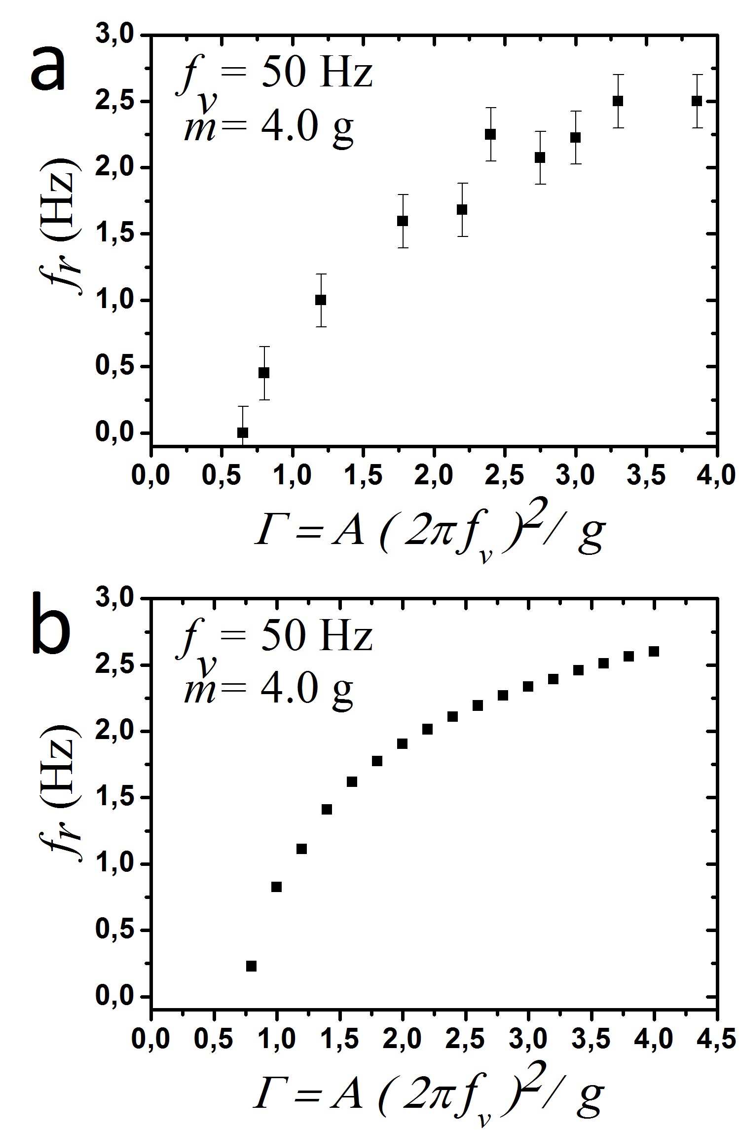
where the relations , and , have to be satisfied. Fig. 4 shows a comparison between the experimental and the model results for the dependence of the rotation frequency, for a Vibrot with mass g and a vibration frequency of Hz. For the value of the model accurately predicts the experimental results.
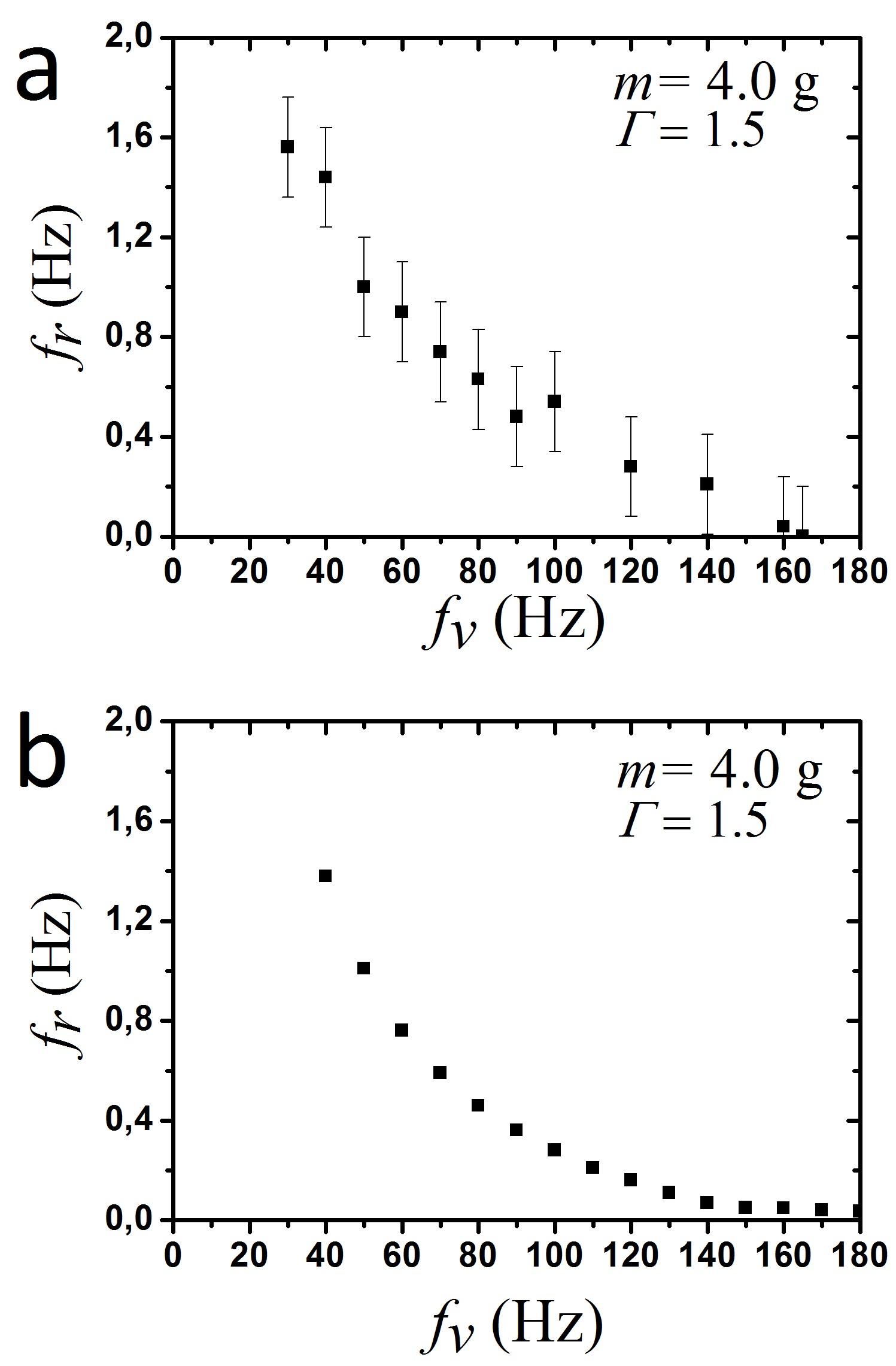
In Fig. 5 we can see how the rotation frequency decreases as the vibration frequency increases, for a Vibrot with mass g and a dimensionless acceleration, . Also, it shows a very good agreement between the experiments and the model. However, the latter predicts a “smoother” decay for high vibration frequencies.
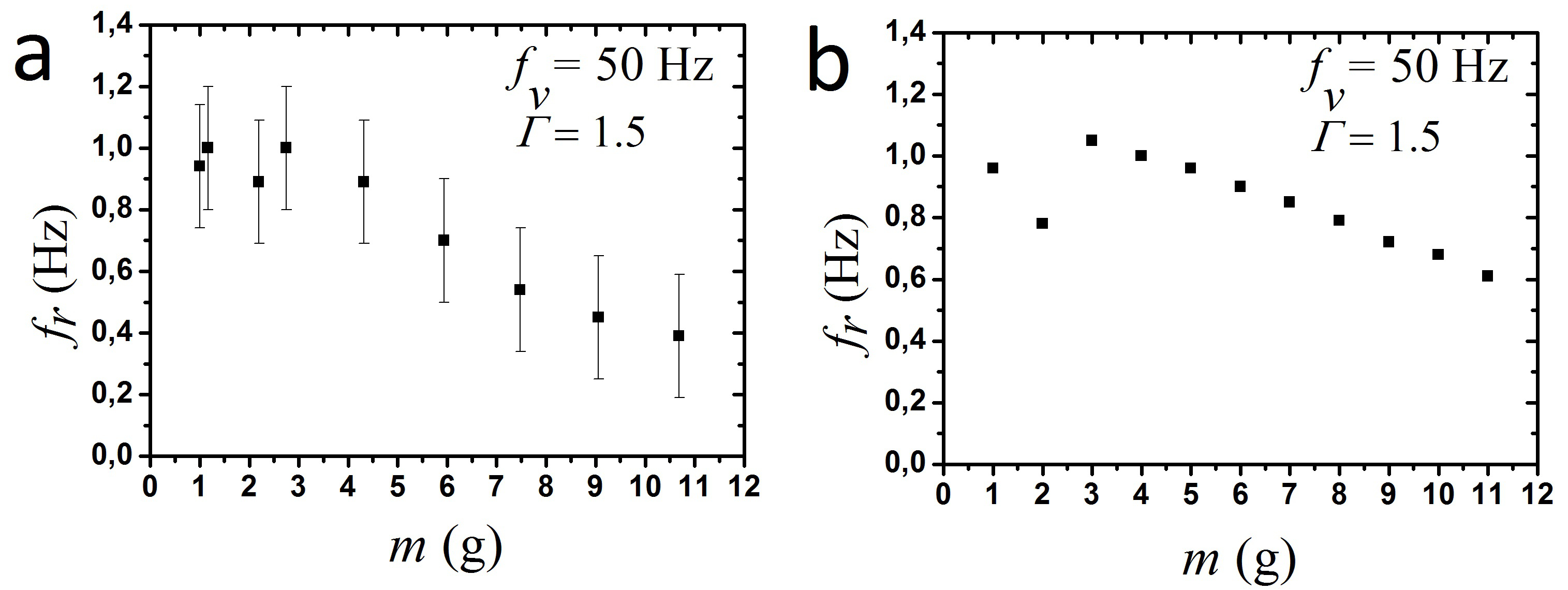
Our model also allows to obtain the mass-dependency of the rotation frequency, . In Fig. 6 we observe a very similar behaviour for small masses between the experiments and the model, but for higher masses the decrease of is slower for the model. This may be due to the fact that the rubber legs of real Vibrots are mechanically deformed for high masses.
It is important to check the model’s results for the case of a Vibrot with rigid legs (). In this particular case, it was experimentally proven that the device does not rotate. This was an expected result since it behaves as a rigid body. With our model, we can corroborate this result, by giving big values to (bigger than N/m). As the elastic constant increases, the rotation frequency decreases, eventually reaching values very close to zero. This fact can be explained taking into account that an increasing of provokes an increasing in the resistance of the springs to the external force (vibrating platform), which implies a smaller amplitude, and bigger velocity and fly time, what finally results in a smaller rotation frequency.
IV Conclusions
We have developed a mechanical model of a Vibrot: a device that, when put on a vibrating platform, is able to rotate due to the presence of inclined elastic legs that interacts frictionally with the vibrating platform. In order to construct the system of differential equations of the model, the reference system was taken on the vibrating platform and the rubbery legs of the experimental Vibrot Altshuler was modeled as linear springs inclined a certain angle relative to the normal of the base of the cylinder, which represents its body. The loss of energy mechanism was proposed as a viscous force in the vertical axis and a kinetic friction force in the angular direction. All the values to construct the model were taken from Altshuler , except the coefficient of the viscous force, which was determined by fitting the experimental data and the friction coefficient, which was taken from the literature.
In spite of the relative simplicity of our model -entirely based in Newtonian mechanics- we have been able to reproduce semi-quantitatively or quantitatively most experimental observations on the Vibrots reported in Altshuler . The few discrepancies with experimental data are only quantitative, an dare probably due to the fact that we did not model the mechanical deformations of the shape of the legs (especially bending) due to the weight of the Vibrot body.
Acknowledgment
We would like to thank to Diego Maza for providing experimental data.
References
- (1) C. Rorres, “The Turn of the Screw: Optimal Desing of an Archimedes Screw”, Journal of Hydraulic Engineering. (January, 2000)
- (2) Santos , Daryl, and Sunil Chhabra. “An Analysis of Archimedes Screw Design Parameters and their Influence on Dispensing Quality for Electronics Assembly Applications.” State University of New York at Binghamton
- (3) ApSimon, H. G. “Archimedean Screws.” Mathematical Gazette. 41.35 (February, 1957): 38-40. Web. 27 Mar. 2013 http://www.jstor.org/stable/311535.
- (4) La estatua egipcia que se mueve por si misma, http://mitosytimos.blogspot.com/2013/06/la-estatua-egipcia-que-se-mueve-por-si.html (September 8th, 2015).
- (5) Altshuler E., Pastor J.M., Garcimartín A., Zuriguel I., Maza D. “Vibrot, a Simple Device for the Conversion of Vibration into Rotation Mediated by Friction: Preliminary Evaluation.” PLoS ONE 8(8): e67838. doi:10.1371/journal.pone.0067838 (2013)