Buoyancy effect on the flow pattern and the thermal performance of an array of circular cylinders
Abstract
In this paper we found, by means of numerical simulations, a transition in the oscillatory character of the flow field for a particular combination of buoyancy and spacing in an array of six circular cylinders at a Reynolds number of and Prandtl number of . The cylinders are iso-thermal and they are aligned with the Earth acceleration (). According to the array orientation, an aiding or an opposing buoyancy is considered. The effect of natural convection with respect to the forced convection is modulated with the Richardson number, , ranging between and . Two values of center to center spacing () are considered. The effects of buoyancy and spacing on the flow pattern in the near and far field are described. Several transitions in the flow patterns are found and a parametric analysis of the dependence of the force coefficients and Nusselt number with respect to the Richardson number is reported. For , the change of spacing ratio from to induces a transition in the standard deviation of the force coefficients and heat flux. In fact the transition occurs due to rearrangement of the near field flow in a more ordered wake pattern. Therefore, attention is focused on the influence of geometrical and buoyancy parameters on the heat and momentum exchange and their fluctuations. The available heat exchange models for cylinders array provide a not accurate prediction of the Nusselt number in the cases here studied.
drag and lift coefficients \entryforce components, \entryheat transfer coefficient, \entrytemperature, \entryinflow temperature, \entrycylinder temperature, \entryinflow velocity, \entrycylinder diameter, \entryfrequency, \entryEarth acceleration, \entryfluid thermal conductivity, \entrydimensionless pressure \entrytransversal cylinder spacing, \entryin-line cylinder spacing, \entrydimensionless fluid velocity vector Greek Letters
cylinder-inflow temperature difference, ; \entrythermal expansion coefficient, \entrythermal diffusivity, \entrykinematic viscosity, \entryfluid density, Dimensionless Numbers
Grashof number; \entryNusselt number; \entryPrandtl number; \entryReynolds number; \entryRichardson number; \entryStrouhal number;
1 Introduction
The flow around multiple bluff bodies is a prototype of many engineering problems ranging from heavy-duty to micro-devices applications. Offshore pipelines, electrical power lines, electronic and bio-tech devices are just few examples of applications in which flow interacts with multiple bluff bodies. Among them the heat exchangers involve a wide range of engineering applications. In general, they consist of solid surfaces at a certain temperature immersed in a cross flow at a different temperature. In particular tube bundles heat exchangers are common in several micro applications such as in heat exchange control in Li-ion batteries [1] or in biomedical devices. For instance, the thermal performance of lab-on-chip devices assumes a key role in a wide range of biological applications, such as the study of tumor cells under constant temperature [2]. The small dimensions and the low flow velocity induce unsteady laminar regimes [3]. The oscillations induced by the flow patterns affects the force and thermal response of such devices that have to be taken into account in the design process [4, 5]. Indeed the prediction of the performance of these devices is still the subject of study. Numerical simulation of the flow field and heat exchange aids to give a detailed overview of the flow quantities involved in such a flow. In the present study the flow field around six circular cylinders has been investigated by means of numerical simulations. Three dimensionless parameters are involved in this type of problem: the Reynolds (), Prandtl () and Richardson () number defined as:
| (1) |
where , , and are , respectively, the inflow velocity, the cylinder diameter, the kinematic viscosity of the fluid and its thermal diffusivity. is the Grashof number where , and are, respectively, the Earth acceleration modulus, thermal expansion coefficient and the temperature difference between the cylinder surface and the cross flow free stream temperature. The Richardson number represents the importance of the natural convection with respect to the forced convection. Usually the range in which both effects are present is characterized by values of and it is called mixed convection. The higher is the absolute value of the Richardson number the smaller is the effect of the convection forced by the inlet velocity with respect to the natural convection. Forced convection, , is the first step to study the heat exchange between the bluff bodies and the flow. In this case the flow is not influenced by temperature in the hypothesis of small temperature differences between the bluff bodies and the flow temperature with respect to the dominant velocity convection. In Fornarelli et al. [6] the authors investigated the flow field and the heat exchange around six circular cylinders by means of numerical simulation. The tests have been done in case of forced convection (), and a transition in the flow patterns and in the heat exchange has been identified. The flow pattern transition occurred for a spacing ratio between and . The flow is unsteady and the heat exchange of each cylinder is strongly influenced by the vorticity dynamics. The influence of the buoyancy force on the flow field is expected to be important in order to change the flow and heat transfer dynamics. The buoyancy force influences both the near and the far field with respect to a solid obstacle immersed in a flow affecting the boundary layer separation and the onset of the vortex shedding in the wake [7, 8]. In a two cylinders configuration, mixed convection with aided buoyancy, aligned to the free stream velocity, has a stabilizing effect on the flow pattern, vice versa the opposed buoyancy anticipates the boundary layer separation at the cylinder surface and makes the flow more unstable [9]. Nevertheless a simple two bodies model is not able to predict the multiple cylinders configuration behaviour because of a more complex wake interference phenomenon that affects the downstream cylinders. In literature, the in-line configuration of multiple heated cylinders considering the effect of buoyancy force has not been extensively investigated. Khan et al. [10] studied the thermal response of isothermal tube bundle of circular cylinders in in-line and staggered configuration over a wide range of Reynolds number but only in case of forced convection () using an integral solution of the boundary layer equations. Multiple row configurations have been studied focusing on the characterization of the mean value of the force and the heat transfer coefficients [11, 12]. The analytical results are able to model a wide parameter range in the hypothesis of an infinite number of rows, but the unsteady characteristics cannot be extrapolated. Moreover at a Reynolds number of the effects of wake interference on the heat exchange is not easily predictable by means of simplified models [13, 14]. The aim of the present work is to shed light on the oscillatory characteristic of the force and heat transfer coefficients in case of a single in-line array of six circular cylinders. In order to retain the two-dimensional character of the flow field, our simulations have been carried out at , being in literature, for the case of a single cylinder, the threshold for the transition from two to three-dimensional flow [15] and also for two identical in-line cylinders, in a wide range of in-line spacings, the two dimensional character of the flow is retained at , as reported in the works of Carmo et al. [16, 17]. They state that the onset of three-dimensional instabilities, for a spacing ratio between and , occurs for . Three-dimensional instabilities induced by the buoyancy force are limited being the buoyancy force modulated in the range [18, 19, 20]. A detailed description of the flow patterns and temperature distribution have been reported. Moreover the dependence of the dimensionless force and heat transfer coefficients () have been reported with a quantitative analysis of their mean and oscillating components.
2 Numerical setup
The incompressible two-dimensional Navier-Stokes equations and the heat transfer equation are considered. Here follows the governing equations in dimensionless form:
| (2) |
| (3) |
| (4) |
where lengths are scaled by the cylinder diameter () and the velocities by the free-stream velocity (). The temperature is scaled with respect to the free-stream temperature () and the constant temperature of the cylinders () as follows:
| (5) |
In the momentum equation ( 2), in order to take into account the buoyancy force, the Boussinesq approximation has been considered . represents the ratio between the buoyancy and the inertial force. The gravity vector is aligned with the streamwise direction . The Reynolds number and the Prandtl number have been kept fixed, and , respectively. Direct numerical simulations have been performed using a fractional step projection method to enforce the continuity equation with a pressure correction approach [21]. The advection terms are treated by means of a Godunov procedure using a second order upwind method. For the viscous terms an implicit Crank-Nicholson scheme has been implemented. The Poisson equation for the pressure correction step is iterated until the local error on the continuity equation is greater than . In fig. 1 a schematic representation of the computational domain and boundary conditions is shown. The numerical domain is long in the streamwise direction and wide in the transversal direction. An adaptive mesh refinement approach has been implemented in the numerical code [21]. The refinement strategies include the limiting of the velocity and temperature difference between two adjacent grid cells every time-step. A detailed and comprehensive grid independence study and a sensitivity analysis on the domain dimension has been carried out as reported in a previous work of the authors [6]. At the inflow uniform flow is imposed with , and , while at the outflow the spatial variation of the velocity components and temperature in the streamwise direction are imposed as follows: , and . Symmetry boundary conditions are imposed on the walls (, and ). The cylinders surfaces are kept at a constant dimensionless temperature equal to whereas the inlet flow temperature is . The spacing between the cylinders is constant and two different values are considered, and . All the quantities reported in the results section are averaged over dimensionless time units () in order to achieve the convergence of the statistics. To ensure initial condition independence of the results statistics are collected after .

The numerical results of the force coefficients and heat transfer coefficient are reported. Here, is the drag coefficient, is the lift coefficient and is the Nusselt number, which are defined as:
| (6) |
where and are the drag and lift force per unit length, respectively. is the local heat transfer coefficient and is the thermal conductivity.
3 Results
3.1 Effect of spacing and buoyancy force on temperature spatial distribution
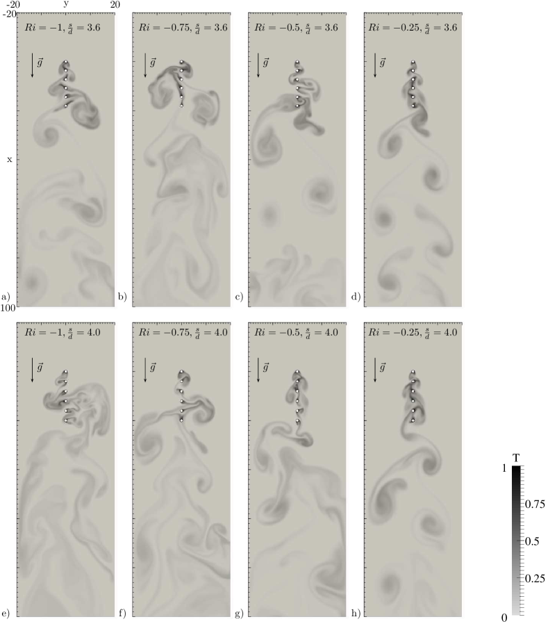
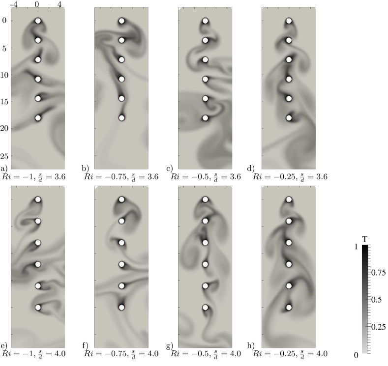
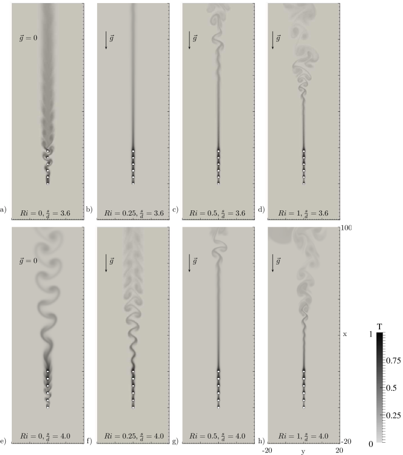
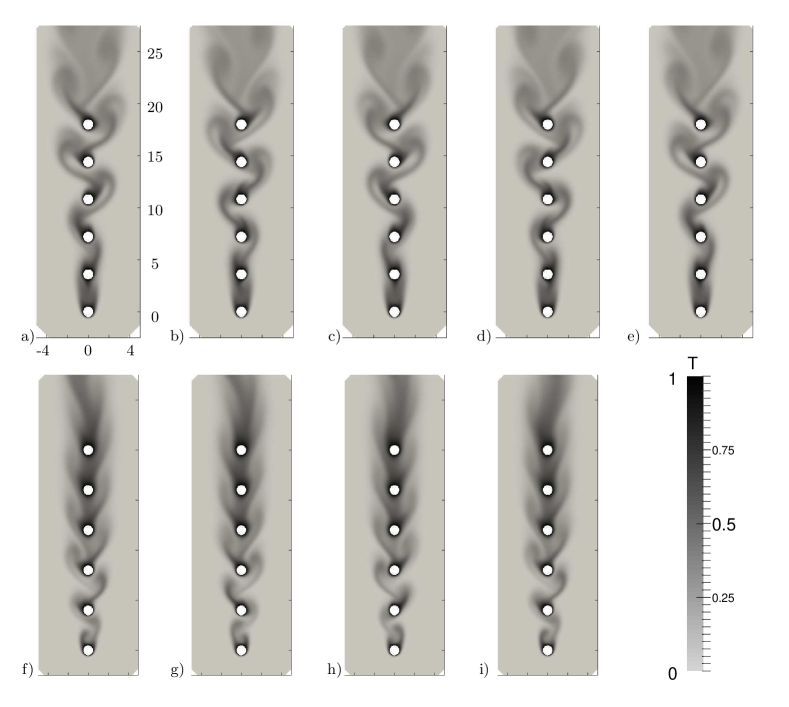
The flow and thermal behaviour of six in-line cylinders configuration as function of the Richardson number for two values of spacing ratio are investigated. First, a qualitative comparison of the temperature distribution contours at the same instant is reported. In fig. 2 opposing buoyancy cases () are shown; in these cases, due to the complex spatial distribution of the temperature contours, a close up of the near field is also reported in fig. 3. In fig. 4 forced convection and aiding buoyancy cases () are shown. The figures are oriented according to the direction of the gravity vector, . Thus, the free stream velocity is oriented downward or upward for negative or positive values of , respectively. The counter-oriented buoyancy induces a thermal wake widening, instead of the aiding buoyancy cases, where the wake appears narrower. This phenomenon affects both the spacings remarking that the buoyancy influences the boundary layer separation around bluff obstacles as already described in previous analogous studies [9, 7]. In case of forced convection, , the configuration does not show a secondary instability of the wake, whereas at the wake evolves in a meandering configuration as described in Fornarelli et al. [6] (fig. 4a-e). This behaviour is related to the flow structures shed by the cylinders. In fig.5 the temperature distributions of about one oscillating cycle at for both the spacings are reported. At (fig.5a-e) a phase shift in the shedding behaviour of two successive cylinders produces alternate shedding structures on the right and left hand side with respect to the array centerline. Whereas, at (fig.5f-i) the flow structures are shed in phase. In case of mixed convection, the opposing buoyancy widens the wake according to the enhanced boundary layer separation at the cylinders surface. Indeed for the buoyancy force adds its contribution as source term in the momentum equation, eq. (2), affecting the streamwise component of the velocity, especially near the cylinders, where the temperature is the highest. Being the cylinders the only source of vorticity, the flow patterns and the temperature distribution are very sensitive to . In particular for the opposing buoyancy force induces the boundary layer instabilities in the near field as reported in detail in fig.3. It is worth to note that for both the spacings, in the cases of (fig. 2-a,b,c,e,f,g), the opposing buoyancy affects the vortex shedding of the array. The more is the opposing buoyancy the more chaotic the temperature pattern appears, except for the case with at (see fig. 2-a). Although at a more chaotic configuration is expected, at , enhancing the opposing buoyancy from to , a well-ordered wake pattern can be recognized, due to a reorganization of the vorticity interaction in the near field of the array. Hence, consequences on the performance of the array in terms of force and heat exchange are expected and will be detailed below. On the other hand the aiding buoyancy, , stabilizes the flow field. With respect to the case of forced convection the wake is narrower. The flow field around the cylinders appears very stable and no shedding structures appear behind the array. For and the temperature distribution in the flow field reveals a stable wake pattern without any secondary instability, even in the far field (see fig. 4-b). The increasing of the buoyancy force triggers a Kelvin-Helmholtz instability of the wake in the far field. For the increasing of from to is not sufficient to suppress the wake oscillation (see fig. 4-f). Increasing the buoyancy force at , the wake oscillation is suppressed and there is only a secondary oscillation in the far field (see fig. 4-g).
3.2 Drag and lift forces analysis
The drag coefficient of the entire array, has been measured for each value of and . Being a function of time, its time average, , and standard deviation, , have been calculated. In fig. 6 the time averaged drag coefficient is reported. The opposing buoyancy reduces the drag of the array with respect to the force convection case for both the spacings. At , a minimum time average drag coefficient is found, reaching negative values, for and for . Indeed, at , the drag coefficient are at and at . For the forced convection and the aiding buoyancy cases, , the time averaged drag coefficient increases linearly:
| (7) |
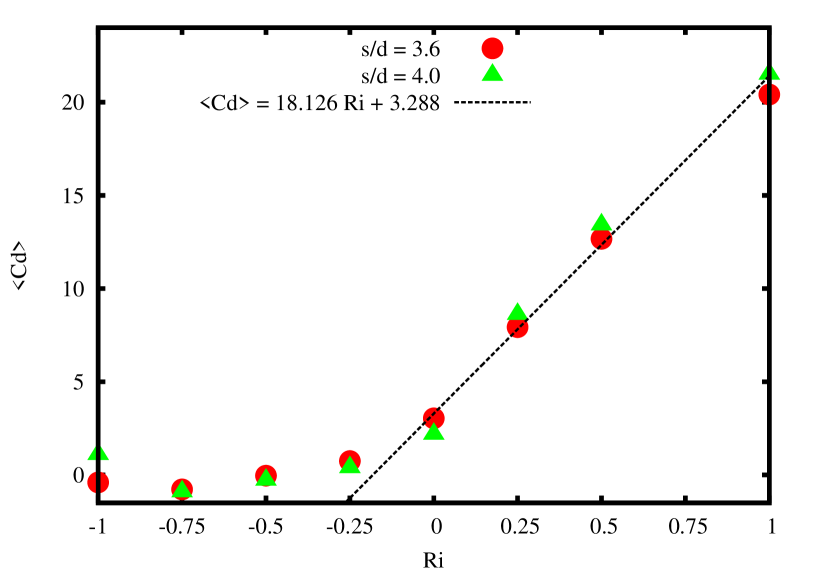
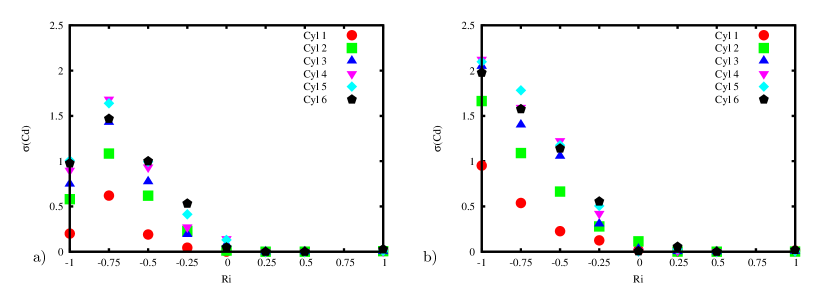
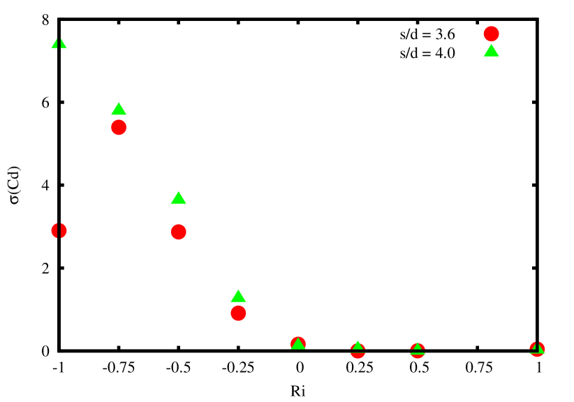
On the other hand, in fig. 8 the standard deviation of the drag coefficient shows an increase of its oscillating amplitude in opposing buoyancy cases. The aiding buoyancy suppresses the drag coefficient oscillation, as described in the qualitative description of the temperature distribution in the previous section. A sudden transition, at , changing the spacing between the cylinders is found. The decreasing of the spacing from to causes a limiting effect on the oscillation amplitude of . The standard deviation of the drag force coefficient () of the array has been detailed on each cylinder in fig. 7. It is worth to note that all the cylinders are involved in the transition at .
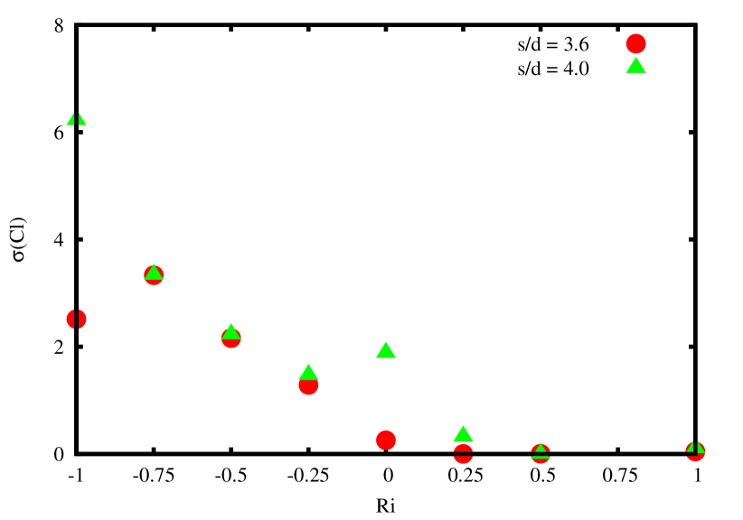
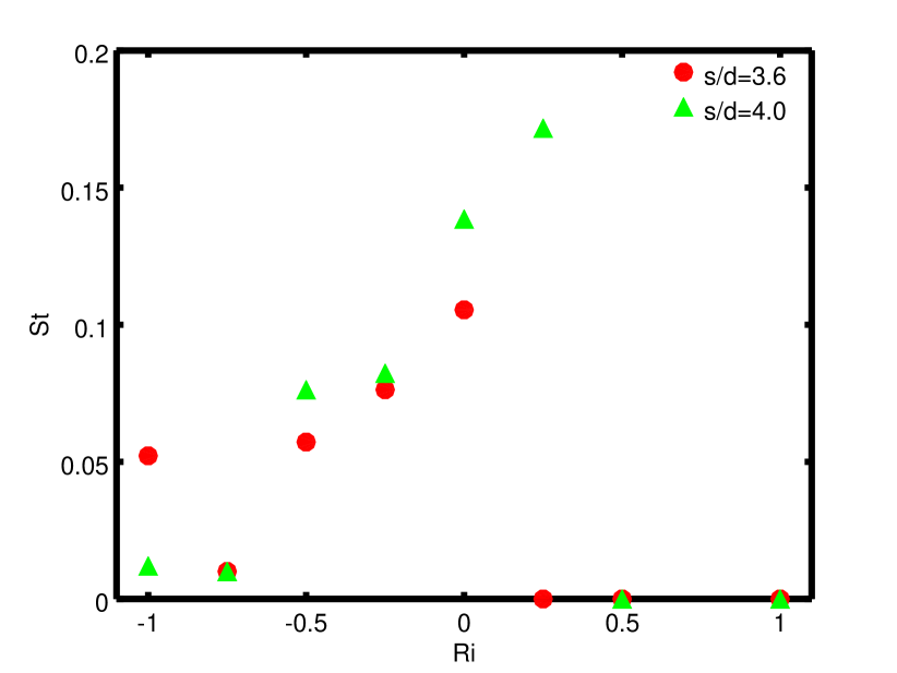
This result is strictly connected with the flow pattern transition depicted in fig. 2. The standard deviation of the lift coefficient, , confirms the transition at (see fig. 9). Moreover, the temperature distribution in the near field reveals that for the boundary layer separations at the cylinder surfaces are reduced (see fig. 3-a), compared to the spacing (see fig. 3-e), inducing a dumping in the oscillation amplitude of and . At and a difference in the value of can be recognized. Indeed it is related to the wake oscillation of the case with respect to the stable configuration of remarking the qualitative discussion about the instantaneous temperature distribution reported in section 3.1. is more sensitive than to the wake oscillation in the near field. In figure 10 the Strouhal number (, where is the oscillation frequency) of the maximum peak of the fft of the for the first cylinder is reported. The higher differences in the oscillation frequency correspond to the cases at and , where different temperature patterns have been recognized changing the spacing ratio between the cylinders. At the sudden jump of is related to the above mentioned boundary layer separation reduction that influences the shedding behaviour at compared to the case at .
3.3 Heat exchange performance
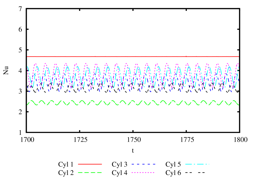
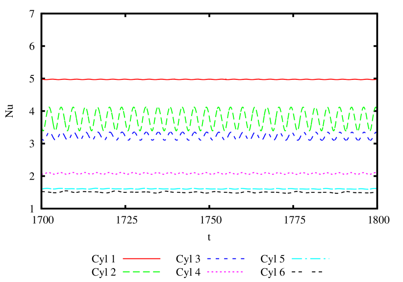
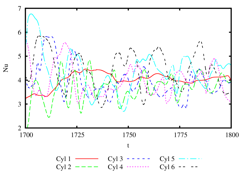
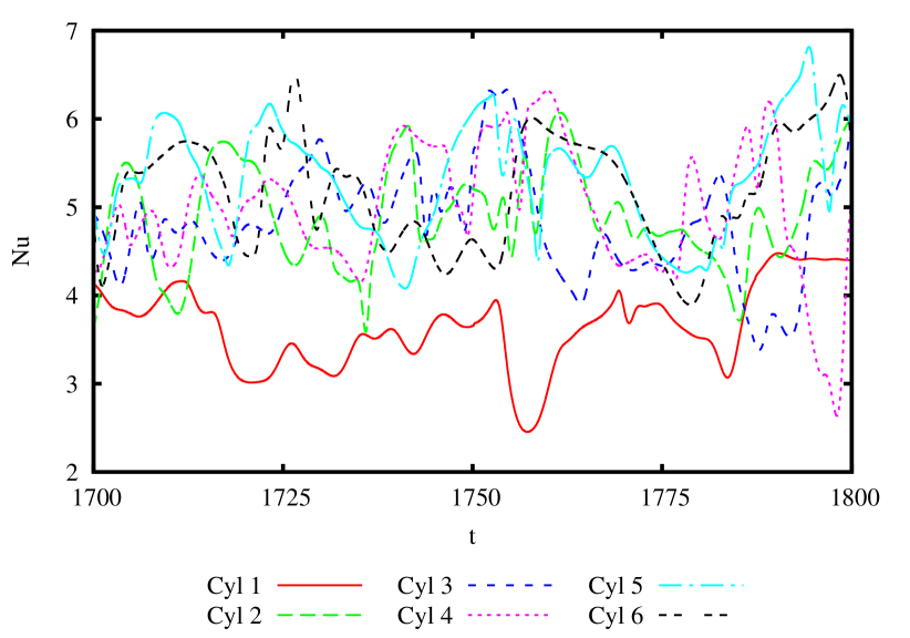
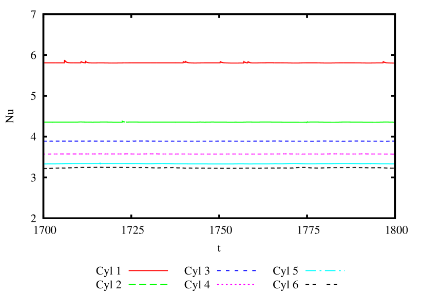
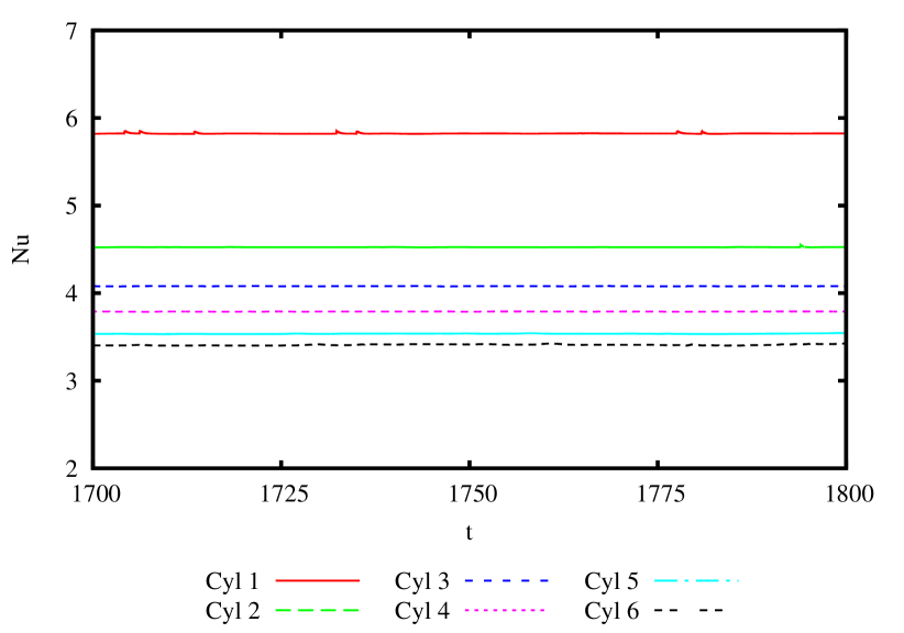
The thermal performance of the cylinders array with respect to the buoyancy force modulation is evaluated by means of the Nusselt number. The instantaneous surface averaged Nusselt numbers, , for each cylinder have been sampled during the simulations. It is obtained averaging the local Nusselt number, . The forced convection case () shows a monochromatic response of the surface averaged Nusselt number for each cylinder for both the spacing ratio, (fig.11) and (fig.12). The opposing buoyancy () induces more complex oscillations of as reported in fig. 13 for and in fig.14 for . On the other hand, the aiding buoyancy, for , suppresses the oscillations on all the cylinders as reported in fig. 15 for and in fig. 16 for . Thus, the time averaged Nusselt number, , and its standard deviation, , have been extracted. First, the time-average Nusselt number of the entire array is analyzed (see fig. 17).
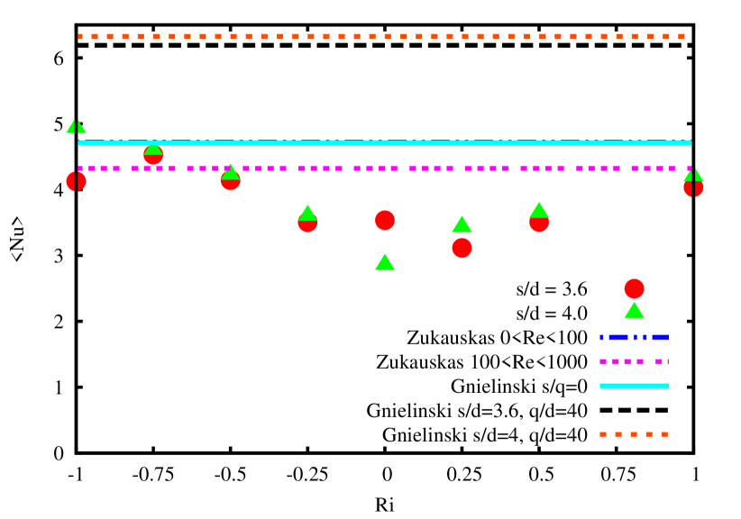
The results are compared to the prediction of time-averaged heat exchange in case of tube banks of Zukauskas [13]:
| (8) |
where , and are related to the Reynolds number, whereas is a correction factor for an array of less then cylinders. The values of the coefficients here considered are reported in table 1. The influence of longitudinal and transversal spacing between the cylinders are not included in the model.
Gnielinski [14] extends the prediction model of the Nusselt number for a single cylinder to the tube bundle case introducing a correction term () including the influence of longitudinal () and transversal () spacing ratio:
| (9) |
where
Imposing and the void ratio , a single line of cylinders can be approximated. In these hypotheses, the Gnielinski [14] model remarks the result of Zukauskas [13] in the range . The model is very sensitive to the transversal spacing, i.e., considering in the Gnielinski [14] model, according to the influence of multiple lines, the Nusselt number increases up to and for and , respectively. According to the numerical simulations, and influence the averaged Nusselt number that the simplified models overestimate. The higher spacing between the cylinders gives rise to a higher Nusselt number in case of aiding or opposing buoyancy. However, in case of forced convection the tighter spacing, , leads to a higher heat exchange. According to Fornarelli et al. [6], such behaviour is related to an enhanced cold fluid entrainment in the gap between two successive cylinders for the case, due to the near field flow oscillation (see fig. 5). It is worth to note that the minimum for and corresponds to and respectively. The increase of opposing or aiding buoyancy force induces a quasi-symmetrical heat transfer enhancement. case is well approximated by the Zukauskas [13] and Gnielinski [14] models for both spacings. induces a different behaviour for the two spacings here considered. Thus, with respect to , the tighter configuration () shows a reduction of Nusselt number. For , at the Nusselt number reaches its maximum ().
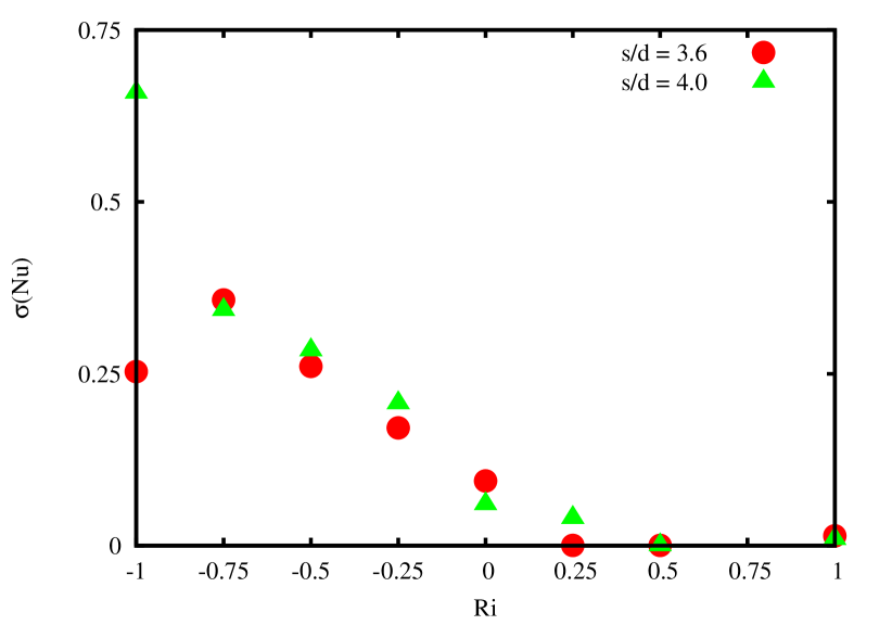
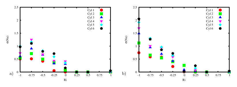
Figure 18 shows the amplitude of the oscillation with respect to the and the spacing ratio. The buoyancy effect on the flow pattern influences the amplitude of the averaged Nusselt number. The behaviour of the standard deviation of the Nusselt number shows the stabilization effect of the aiding buoyancy except for and . The wake oscillation depicted in the instantaneous temperature distribution for and , reported in fig. 4-f, causes the onset of Nusselt amplitude even in the case of aiding buoyancy. The opposing buoyancy increases the oscillation amplitude of the heat exchange. From to a linear increase of the standard deviation of for both spacings has been found. The small differences of for the two spacings are influenced by the wider gap between the cylinders of the case. The further increase of opposing buoyancy force, shows a transition of the oscillation amplitude of Nusselt number for the two spacing. The , case holds an increase of the amplitude of reaching , otherwise at . The of each cylinder is reported in fig. 19. At the spacing ratio increase produces higher oscillations of Nusselt number on each cylinder. At the spacing increase enhances the of the first cylinder. At the higher value of the averaged reported in fig. 18 at is mainly related to the oscillating amplitude of the trailing cylinders.
4 Conclusions
We can infer, by means of numerical simulations, that the buoyancy force and the spacing between the cylinders, arranged in a single six elements row, affect their performance in terms of forces and heat exchange. Generally, the aiding or the opposing buoyancy induces a stable or unstable behaviour of the flow, respectively. However, in case of opposing buoyancy a flow transition has been recognized. In case of aiding buoyancy the spacing influences the secondary instability of the wake in the far field, therefore the differences in terms of force and heat exchange between the fluid and the cylinders are small because they are linked with the near field behaviour. On the other hand, in case of opposing buoyancy the flow instabilities in the near field affect the array performance. The oscillation amplitudes of , and become relevant with respect to the mean quantities for both the spacing here investigated. At the spacing affects heavily the oscillation amplitude of the measured quantities. At and the standard deviation of the performance coefficients, , and increases with . However, for a spacing ratio , even with a strong opposing buoyancy (), the flow is able to rearrange itself in a more ordered wake pattern configuration limiting the oscillation amplitude of the performance coefficients. In the range of parameters here presented, the heat exchange and force coefficients of the cylinders array appear very sensitive with respect to the value of Richardson number. Thus, this work highlights the care that should be taken in using existing predictive models to estimate the heat transfer around a finite number of circular cylinders in case of mixed convection.
The authors would like to thank the IT staff of “Centro Cultura Innovativa d’Impresa” of “University of Salento”, where the simulations were carried out, for their technical help.
References
- [1] Ye, Y., Saw, L. H., Shi, Y., and Tay, A. A., 2015. “Numerical analyses on optimizing a heat pipe thermal management system for lithium-ion batteries during fast charging”. Applied Thermal Engineering, 86, pp. 281 – 291.
- [2] Wan, Y., Tamuly, D., Allen, P. B., Kim, Y.-t., Bachoo, R., Ellington, A. D., and M., I. S., 2013. “Proliferation and migration of tumor cells in tapered channels”. Biomedical Microdevices, 15(4), pp. 635–643.
- [3] Wang, S.-y., Tian, F.-b., Jia, L.-b., Lu, X.-y., and Yin, X.-z., 2010. “Secondary vortex street in the wake of two tandem circular cylinders at low reynolds number”. Phys. Rev. E, 81, p. 036305.
- [4] Duryodhan, V. S., Singh, A., Singh, S. G., and Agrawal, A., 2016. “A simple and novel way of maintaining constant wall temperature in microdevices”. Scientific Reports, 6(18230), pp. 1–15.
- [5] Selimefendigil, F., and Oztop, H., 2014. “Control of laminar pulsating flow and heat transfer in backward-facing step by using a square obstacle”. Journal of Heat Transfer, 136(8).
- [6] Fornarelli, F., Oresta, P., and Lippolis, A., 2015. “Flow patterns and heat transfer around six in-line circular cylinders at low reynolds number”. JP Journal of Heat and Mass Transfer, 11(1), pp. 1–28.
- [7] Chatterjee, D., 2014. “Dual role of thermal buoyancy in controlling boundary layer separation around bluff obstacles”. International Communications in Heat and Mass Transfer, 56, pp. 152–158.
- [8] Clifford, C., and Kimber, M., 2014. “Optimizing laminar natural convection for a heat generating cylinder in a channel”. Journal of Heat Transfer, 136(11).
- [9] Patnaik, B., Narayana, P., and Seetharamu, K., 2000. “Finite element simulation of transient laminar flow past a circular cylinder and two cylinders in tandem”. International Journal of Numerical Methods for Heat and Fluid Flow, 10(6), pp. 560–580.
- [10] Khan, W., Culham, J., and Yovanovich, M., 2006. “Convection heat transfer from tube banks in crossflow: Analytical approach”. International Journal of Heat and Mass Transfer, 49(25-26), pp. 4831–4838.
- [11] Wang, Y., Penner, L., and Ormiston, S., 2000. “Analysis of laminar forced convection of air for crossflow in banks of staggered tubes”. Numerical Heat Transfer; Part A: Applications, 38(8), pp. 819–845.
- [12] Gowda, Y., Narayana, P., and Seetharamu, K., 1998. “Finite element analysis of mixed convection over in-line tube bundles”. International Journal of Heat and Mass Transfer, 41(11), pp. 1613–1619.
- [13] Zukauskas, A., 1972. “Heat transfer from tubes in crossflow”. Vol. 8 of Advances in Heat Transfer. Elsevier, pp. 93 – 160.
- [14] Gnielinski, V., 1975. “Berechnung mittlerer wärme- und stoffübergangskoeffizienten an laminar und turbulent überströmten einzelkörpern mit hilfe einer einheitlichen gleichung”. Forschung im Ingenieurwesen, 41(5), pp. 145–153.
- [15] Barkley, D., and Henderson, R., 1996. “Three-dimensional floquet stability analysis of the wake of a circular cylinder”. Journal of Fluid Mechanics, 322, pp. 215–241.
- [16] Carmo, B. S., Meneghini, J. R., and Sherwin, S. J., 2010. “Secondary instabilities in the flow around two circular cylinders in tandem”. Journal of Fluid Mechanics, 644, pp. 395–431.
- [17] Carmo, B., Meneghini, J., and Sherwin, S., 2010. “Possible states in the flow around two circular cylinders in tandem with separations in the vicinity of the drag inversion spacing”. Physics of Fluids, 22(5), pp. 1–7.
- [18] Maas, W., Rindt, C., and van Steenhoven, A., 2003. “The influence of heat on the 3d-transition of the von kármán vortex street”. International Journal of Heat and Mass Transfer, 46(16), pp. 3069–3081.
- [19] Ren, M., Rindt, C., and van Steenhoven, A., 2004. “Experimental and numerical investigation of the vortex formation process behind a heated cylinder”. Physics of Fluids, 16(8), pp. 3103–3114.
- [20] Boirlaud, M., Couton, D., and Plourde, F., 2012. “Direct numerical simulation of the turbulent wake behind a heated cylinder”. International Journal of Heat and Fluid Flow, 38, pp. 82–93.
- [21] Popinet, S., 2003. “Gerris: a tree-based adaptive solver for the incompressible euler equations in complex geometries”. Journal of Computational Physics, 190(2), pp. 572–600.