Thin film superfluid optomechanics
Abstract
Excitations in superfluid helium represent attractive mechanical degrees of freedom for cavity optomechanics schemes. Here we numerically and analytically investigate the properties of optomechanical resonators formed by thin films of superfluid 4He covering micrometer-scale whispering gallery mode cavities. We predict that through proper optimization of the interaction between film and optical field, large optomechanical coupling rates kHz and single photon cooperativities are achievable. Our analytical model reveals the unconventional behaviour of these thin films, such as thicker and heavier films exhibiting smaller effective mass and larger zero point motion. The optomechanical system outlined here provides access to unusual regimes such as and opens the prospect of laser cooling a liquid into its quantum ground state.
pacs:
67.25.dt, 67.25.dp, 42.60.Da, 42.82.Et-
September 2nd, 2016
Keywords: cavity optomechanics, superfluidity, superfluid helium films, optical resonators, third sound, effective mass, liquids.
1 Introduction
The field of cavity optomechanics[1] focuses on the interaction between confined light and a mechanical degree of freedom. Optomechanical techniques enable an exquisite degree of control over the motion of micromechanical resonators, with successful examples including ground-state cooling [2] and squeezing of the mechanical motion of a resonator [3]. Recently, in a push to extend the realm of applications to biological systems, there has been a growing interest in the study of resonators immersed or interacting with liquids [4, 5, 6], or the use of liquids as resonators [7]. In parallel, a special type of quantum liquid, namely superfluid helium, has also garnered significant attention for optomechanical applications, but for a different reason: the motivation here being the ultra-low optical and mechanical dissipation it can provide due to its reduced optical scattering [8] and absence of viscosity [9, 10]; with both properties being particularly desirable for quantum operations.
To date, the majority of superfluid optomechanics schemes have relied on bulk helium, with implementations taking for example the form of a gram-scale resonator coupled to a superconducting microwave resonator [9], a capacitively-detected superfluid Helmholtz resonator [11] or a helium-filled fiber cavity [12].
In contrast, our group recently demonstrated an approach to superfluid optomechanics based on femtogram thin films of superfluid 4He condensed on the surface of a microtoroidal whispering gallery resonator [13, 14]. Leveraging the techniques of cavity optomechanics, we demonstrated real-time observation of the superfluid Brownian motion, laser cooling of the superfluid excitations [13], as well as the possibility to apply large optical forces at the microscale arising from the atomic recoil of superfluid helium flow [14]. However these devices, while exhibiting strong photothermal coupling, suffered from reduced radiation pressure coupling due to a poor overlap between the optical field and the superfluid mechanical excitations (known as third sound [15], see sec. 3).
In this work, we theoretically design a superfluid thin film resonator from the ground up, carefully optimizing the interaction between superfluid film and optical field (section 2), in order to maximize the dispersive radiation-pressure optomechanical coupling. We investigate three different resonator geometries (microdisk, annular microdisk and microsphere), and provide useful analytical expressions for the effective mass and zero-point motion of superfluid films (section 3), as well as the scaling of optomechanical figures of merit with experimental parameters such as resonator dimensions and superfluid film thickness (section 4). Based upon this analysis, we predict large optomechanical coupling rates kHz and single photon cooperativities greater than 10 are achievable with experimentally accessible designs, as well as unconventional regimes such as greater than the mechanical resonance frequency .
Superfluid thin films present a number of desirable properties: they are naturally self-assembling on the surface of any resonator due to a combination of ultra-low viscosity and attractive van der Waals forces [10], they can be of extremely minute volume, with third sound detected in films only two monolayers thick [16] and they offer a large degree of tunability as their thickness and the frequency of the excitations they sustain can be swept in-situ over a large range simply by changing the helium pressure in the sample chamber. In addition, third sound can exhibit strong Duffing non-linearities, be strongly coupled to quantized vortices [17, 18, 19, 20] and interact with electrons floating on the film [21]. All together, these properties underline the potential of superfluid thin films as a promising platform for cavity optomechanics.
2 Optical field optimization
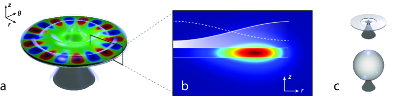
Figure 1 shows a schematic illustration of the optomechanical coupling scheme investigated in this paper. A circular whispering gallery mode (WGM) resonator [22] is uniformly coated with a thin film of superfluid helium [13]. Acoustic waves in this thin film known as third sound [15, 23, 24] manifest as thickness variations which dispersively couple to the confined WGM via perturbations to its evanescent field. As shown in Fig. 1(b), the fluctuating thickness of the superfluid in the vicinity of the WGM induced by a third sound wave modulates the amount of higher refractive index material in the WGM’s near field, thereby changing the optical path length of the resonator. The frequency shift experienced by a WGM of resonance frequency due to the presence of the superfluid thin film is given by a perturbation theory approach [25]:
| (1) |
where is the unperturbed WGM electric field calculated in the absence of superfluid, is the relative permittivity and is the relative permittivity of superfluid helium [26]. The numerator integral is taken over the volume of the film while the denominator integral is taken over all space; Eq. (1) therefore essentially relates the electromagnetic (EM) energy ‘sensing’ the perturbing element (the film) to the total EM energy in the mode.
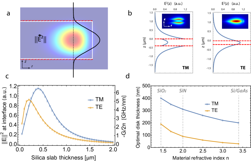
Figure 2(a) plots a FEM simulation of for a transverse electric (TE) [27] WGM of wavelength m confined in a typical silica disk of radius m and 2 m thickness [28]. Overlayed in black is a plot of the vertical dependence of along the dashed black line going through the center of the WGM. The field is mostly confined within the silica resonator, and has low intensity on the top and bottom interface where it is in contact with the superfluid film (red dashes), resulting in weak detection sensitivity/optomechanical coupling through Eq. (1). This limitation can be overcome by a proper choice of disk thickness and WGM polarization so as to maximize the electric field at the interface, as discussed in the following. Figure 2(b) shows the same vertical mode profile for a transverse magnetic (TM) polarized WGM in a 400 nm thick silica disk of identical radius, and for a TE WGM confined in a 200 nm thick disk. Reducing the thickness of the disk pushes the field out of the resonator, increasing over the superfluid region, such that any fluctuation in the film thickness results in a much larger frequency shift of the WGM. Figure 2(c) provides a more systematic investigation of this mechanism. We employ the effective index method (EIM) [27] to calculate the mode profile for a TE and TM guided wave inside a slab waveguide of varying thickness (normalized such that ), recording for each thickness the value of at the interface. For each polarization there is an optimal thickness which maximizes at the interface: too thick and the field is mostly confined within the resonator, too thin and the field becomes very delocalized along z and its value at the interface drops again. From this analysis, we obtain the optimal silica disk thickness for TM (TE) WGMs as approximately 400 nm (200 nm). Next, we repeat the same analysis for different values of the refractive index of the slab, while tracking the optimal thickness for TE and TM WGMs. These results are summarized in Fig. 2(d) and show for instance that for a high refractive index material such as silicon or gallium arsenide, a disk thickness of nm is optimal for TM polarized WGMs. Since these results are based on the EIM, they start to lose accuracy for strongly confining geometries (R on the order of a few ); nevertheless they provide a useful starting point for designing optimized structures. The TM polarized WGMs, with dominant field component normal to the upper and lower interfaces, provide a step increase in the field outside the disk (due to the continuity of ), as shown in Fig. 2(b), and are therefore more sensitive to the superfluid [29].
Since the evanescent field decays along with characteristic length on the order of hundreds of nanometers (Fig. 2(b)), the change in over the typical to 30 nm thickness of the film can safely be neglected. Equation (1) can therefore be rearranged to give the optomechanical optical resonance frequency shift per unit displacement [1, 30, 31]:
| (2) |
where the numerator integral is now a surface integral over the resonator top interface111For simplicity we will in the following consider excitations on the top surface of the resonator, although the treatment follows the same approach for the bottom surface, but with different boundary conditions for the third sound wave due to the presence of the pedestal.. We employ the one dimensional version of Eq. (2) ( ) to provide as a function of resonator thickness in the right axis of Fig. 2(c). As for double-disk optomechanical resonators [32], G is independent of resonator radius and does also not depend on superfluid thickness. Proper choice of resonator thickness is important, resulting for instance in a 20-fold improvement in G for TM modes when going from a 2 m to a 0.4 m thick silica disk. Through this optimization, it is possible to reach large values of G upwards of 6 GHz/nm, despite the challenge posed by superfluid helium’s optical properties being very close to those of vacuum (, ) [26]. This is achieved in part thanks to the perfect spatial overlap provided by the self-assembling nature of the superfluid film: these predicted coupling rates are for instance nearly three orders of magnitude larger than those obtained in experiments in which a silicon nitride string was approached in a microtoroid’s near field [25]. Note additionaly that unlike the previously mentioned scheme in which a perturbing element of constant volume is approached in the near field of a resonator [25, 33, 34, 35], this detection approach does not rely on an electric field gradient along the direction, as we are instead detecting a perturbing element of changing volume.
It is interesting to examine whether large coupling rates can also be achieved for superfluid modes confined to the vertical sidewall of the WGM. For a circular WGM cavity, the sensitivity to a change in radius is given by [36]. From Eq. (2), but integrated along the vertical, rather than top boundary, it can be shown that fluctuations in the thickness of the superfluid film on the vertical boundary would translate to 0.25 GHz/nm with the above parameters.
Here we have discussed the sensitivity to thickness fluctuations affecting either the top, bottom or vertical boundaries of the resonator. Naturally, a variation in the mean thickness of the film would produce a frequency shift of GHz/nm. This means a change in film thickness of 10 pm (i.e. th of a helium monolayer [37]) would be sufficient to shift a WGM resonance with by one linewidth, thereby providing an ultra-precise independent means to optically characterize the superfluid film thickness, a significant improvement over capacitive detection schemes commonly used in the superfluid community [38, 24].
3 Superfluid third sound modes
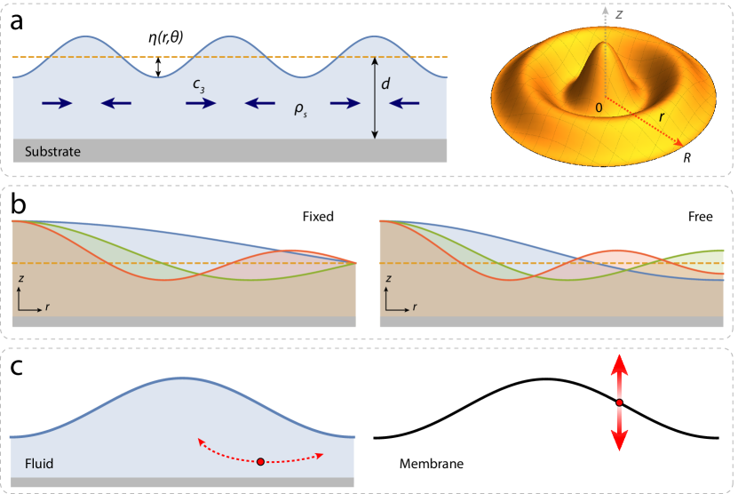
Third sound waves [15, 23, 16, 39, 24, 13] are a type of excitation unique to superfluid thin films which manifest as thickness fluctuations with a restoring force provided by the van der Waals interaction; they are somewhat analogous to water waves (where the restoring force is gravity) [40], see Fig. 3(a). Third sound propagates at a speed given by: [10]
| (3) |
with the ratio of superfluid to total fluid density [10], the van der Waals coefficient characterizing the strength of the attractive force between the helium atoms and the substrate, and the superfluid film mean thickness. The van der Waals coefficients for various resonator materials are provided in Table 1. The dependency in neglects the retardation effects in the van der Waals potential and is a reasonable first order approximation for films 0 to 30 nm thick [37, 41] which we will consider here.
| Material | source | |
|---|---|---|
| Silica | m5s-2 | [42, 16] |
| CaF2 | m5s-2 | [42] |
| Silicon | m5s-2 | [42] |
| MgO | m5s-2 | [37] |
The disk geometry, in addition to providing optical confinement to the WGMs, also confines third sound excitations localized on the top surface, giving rise to third sound resonances. The shape of these resonant modes is dictated by the confining geometry and, for circular resonators, these take the form of Bessel modes as shown in Fig. 3(a) [24, 39, 18]. The third sound mode profile describes the out-of-plane deformation of the superfluid surface for the (; ) mode as a function of time and polar coordinates and :
| (4) |
where and are respectively the azimuthal and radial mode numbers, A the mode amplitude, the Bessel function of the first kind of order , the mode frequency and a frequency parameter depending on the mode order and the boundary conditions, see Table 2. In the following we only focus on the rotationally invariant modes (=0), as these are the ones with largest optomechanical coupling [36].
| n=1 | n=2 | n=3 | n=4 | n=5 | n=6 | n=7 | n=8 | n=9 | n=10 | |
|---|---|---|---|---|---|---|---|---|---|---|
| Free | 3.832 | 7.016 | 10.174 | 13.324 | 16.471 | 19.616 | 22.760 | 25.904 | 29.047 | 32.19 |
| Fixed | 2.405 | 5.520 | 8.654 | 11.792 | 14.931 | 18.071 | 21.212 | 24.353 | 27.49 | 30.63 |
3.1 Boundary conditions
The mode profiles for the first three rotationally invariant third sound modes with fixed () and free () boundary conditions [43] are shown in Fig. 3(b). The free boundary condition is also known as the ‘no flow’ boundary condition, as it requires the radial velocity of the superfluid flow to be 0 at [43], and is therefore volume conserving. On the contrary, the fixed boundary condition does not conserve volume (particularly visible for the (=0; =1) mode), and therefore requires significant flow across the confining boundary, in the incompressible limit. In circular 3He third sound resonators a crossover from free to fixed boundary conditions has been observed for films thicker than nm [44, 43]. For our resonator design, with thin films and near atomically sharp ‘knife-edge like’ [45] microfabricated boundaries, we expect minimal third sound driven flow to occur between the disk’s upper and lower surfaces. This implies free boundary conditions for the third sound wave, consistent with those observed in circular 4He third sound resonators most similar to our design [39, 18].
3.2 Third sound mode effective mass
Calculating the optomechanical single photon coupling strength and single photon cooperativity – useful figures of merit of the optomechanical system [1] (see Eq. (5)) – requires the third sound mode effective mass .
| (5) |
In continuum mechanics, the effective mass at reduction point is obtained by reducing the system to a point mass moving with velocity possessing the same kinetic energy as the original system, that is , or:
| (6) |
For rotationally invariant modes of a thin solid circular resonator of thickness , this leads to the well known expression for the effective mass of a point on the resonator boundary [47]:
| (7) |
Going from Eq. (6) to Eq. (7) assumes the velocity (and density) do not depend on the coordinate, which is valid for both in- and out-of-plane mechanical modes. Here, in order to circumvent the question of the distribution of superfluid velocity [15] and density [16] below the film surface, we use the equipartition theorem to replace the kinetic energy term in Eq. (6) with the van der Waals potential energy stored in the deformation of the film surface. In analogy to gravity waves [40], this energy is given by:
| (8) |
where is the energy per unit mass of the film due to the van der Waals potential [10]:
| (9) |
In the limit of small amplitude surface oscillation , we obtain:
| (10) |
Therefore Eq. (8) becomes for rotationally invariant modes:
| (11) |
As mentioned previously, free (‘no flow’) boundary conditions are volume conserving (), therefore we obtain for the effective mass of a point on the film surface at =:
| (12) |
Finally, using and Eq. (3) we find:
| (13) |
Here we recognize the effective mass of the solid case (Eq. (7)), multiplied by a prefactor proportional to . This means that while for a solid such as a circular membrane scales as expected as (like the real mass), for a third sound wave on a superfluid film scales as —with thicker and heavier films therefore making for lighter resonators possessing larger zero point motion. This radically different scaling can be understood by considering the microscopic motion of a ‘particle’ of the resonator in both cases, as illustrated in Fig. 3(c). Indeed, while the surface deformation in each case is governed by the same mathematical equation (Eq. (4)), a particle in the solid describes an essentially vertical motion while that in a fluid an extremely flattened near horizontal trajectory. As the useful displacement for optomechanical coupling is in the direction, the horizontal particle excursion () and horizontal kinetic energy are ‘wasted’ and appear as a penalty term in the effective mass.
The dependence of underscores the dramatic gains achieved by going towards smaller microfabricated third sound resonators. Indeed, going from a centimeter-scale third sound resonator [18] to a 40 micron radius resonator such as outlined here and demonstrated in Ref. [13] affords —with otherwise identical parameters— a reduction in effective mass and identical boost in cooperativity (Eq. (5)).
4 Optomechanical coupling
In this section we evaluate the performance of superfluid thin films as optomechanical resonators and successively address how this performance is influenced by resonator dimensions, film thickness and mechanical mode order.
4.1 Influence of resonator radius
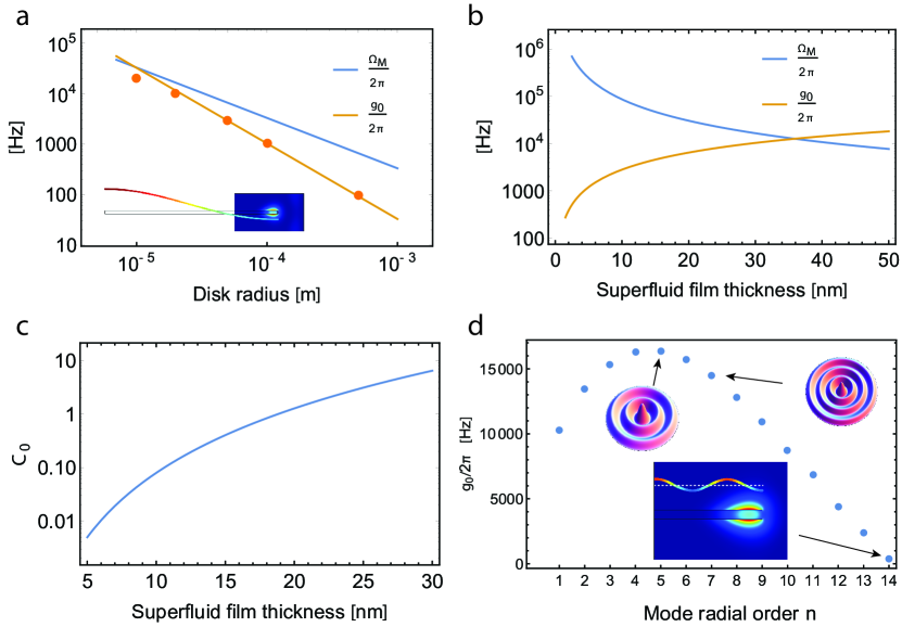
Figure 4(a) plots the dependence of third sound frequency and on resonator radius for the fundamental (=0; =1) third sound mode on a 30 nm thick superfluid film. The solid orange line corresponds to the value of given by Eq. (5), employing the previously determined value of (Eq. (13)) and assuming a constant GHz/nm (see section 2). This is a good assumption for disk radii above m, as the micron sized radial extension of the WGM is small compared to R, and the superfluid displacement is therefore essentially constant over the optical mode (see inset). For smaller radii (and higher order mechanical modes —see section 4.3) the mode overlap between the optical field and the third sound displacement field needs to be taken into account when calculating :
| (14) |
Here is the superfluid displacement profile normalized to at . The orange dots correspond to the results of individual FEM simulations using Eq. (14) with TM WGMs on a 380 nm thick silica disk. The analytical expression is in good agreement with the FEM simulation down to m ( % error), below which it overestimates . Since the mechanical frequency scales as and the zero point motion as , increases faster than as R is reduced, and for the system enters the uncommon optomechanical regime of . Table 3 summarizes the relevant scaling parameters for a disk resonator based on Eqs. (3), (4), (5) and (13).
4.2 Influence of superfluid film thickness
Figure 4(b) plots the dependence of and on superfluid film thickness, for a um resonator. Since scales as and as (see Table 3), both parameters start with extremely dissimilar values for thin films and evolve towards one another as increases. In this particular case, kHz for nm. We take into account the WGM field decay as the film gets thicker, but this is only a minor correction for the thin films we consider here. Next we plot in Fig. 4(c) the dependence of the single photon cooperativity (Eq. (5)) on . For this estimation we consider an optical loss rate MHz corresponding to an optical Q of as demonstrated in thin silica disks of identical radius222The presence of the superfluid helium film around the resonator does not adversely affect the optical Q due to superfluid helium’s ultralow optical absorption in the infrared [13, 12]. [35], and a conservative estimate for the mechanical of 4000, as demonstrated in our previous work with microtoroid resonators [13]. (Note that third sound dissipation rates several orders of magnitude below these values have already been demonstrated [39]). The predicted cooperativity displays a strong dependence on film thickness, reaching large values above unity, with for nm. This value – on par with the state-of-the-art in optomechanical systems [2, 48] – would represent a significant increase in performance compared to existing superfluid optomechanics systems; it corresponds for instance to an over four orders of magnitude increase over recently demonstrated superfluid helium filled fiber cavities [12].
4.3 Influence of third sound mode radial order
The effective mass of a third sound mode is inversely proportional to , as shown in equation (13). This relationship arises because as increases, the ratio of vertical to horizontal superfluid motion becomes more favorable, as the distance between the peaks and the troughs of the third sound wave is reduced (see figure 3). Higher order radial third sound modes (with higher ; see table 2) therefore exibit lower and larger (see Table 3). Note that this is the opposite behaviour to that for a solid membrane, in which decreases with increasing mode order. Figure 4(d) plots results of FEM simulations of versus third sound mode radial order , obtained through equation (14) for a m disk with nm. It reveals two competing trends. First, and initially dominating, is the increase in due to the increase in . Second, for higher , the third sound displacement becomes oscillatory over the WGM (see inset) leading to a dramatically reduced overlap integral, see equation (14). In this particular case reaches its maximal value of kHz for and kHz. The optimal radial order will naturally depend on device dimensions, with larger leading to a larger optimal . These higher order modes provide a twofold benefit: beyond the higher , they have a higher frequency and therefore exhibit a lower thermal phonon occupancy for a given bath temperature. Starting from a base temperature of 20 mK, on the order of intracavity photons would be sufficient to feedback cool [49, 14] this mode into its quantum ground state [2].
4.4 Miniaturized third sound resonators
Finally we briefly address the potential of micrometer-sized WGM resonators made of high refractive index semiconductors such as silicon [50, 29] or gallium arsenide [51, 5] for thin-film superfluid optomechanics. The optimal resonator thicknesses given in figure 2(d) are chosen to maximize the WGM deconfinement, resulting in low WGM effective indices, and therefore do not lend themselves to wavelength-sized radii without incurring significant bending losses [52]. For this reason we consider thicker more confining disks for this application, such as 200 nm thickness for TE modes [51]. This trade-off between sensitivity and optical Q results in a lower on the order of 1 GHz/nm. The kHz (m=0; n=1) third sound mode of a 30 nm thick film confined on top of a R=1 m disk has a zero point motion m at the periphery and a large optomechanical coupling rate reaching up to kHz. Because of the lower optical Q of these resonators however, the expected cooperativity is on par with that expected for larger silica resonators.
5 Conclusion
We have investigated the potential of thin films of superfluid 4He covering micrometer-scale whispering gallery mode cavities as optomechanical resonators. Our analysis predicts large optomechanical coupling and cooperativities are achievable, and provides useful tools for the design of third-sound optomechanical resonators. Furthermore, beyond their sole merits for ‘conventional’ optomechanics, the ability to engineer interactions between third sound phonons and quantized vortices [17, 18, 19, 20] as well as electrons [21], combined with the ability to control superfluid flow on-chip [14] and generate long-lived persistent flows [53], makes this a promising platform with varied applications such as ground-state cooling of a liquid, on-chip inertial sensing [54], single-photon optomechanics [55, 56] and the study of the dynamics of strongly interacting quantum fluids.
Acknowledgments
This work was funded by the Australian Research Council through the Centre of Excellence for Engineered Quantum Systems (EQuS, CE110001013); W.P.B. acknowledges the Australian Research Council Future Fellowship FT140100650.
6 Appendix A: Annular microdisk
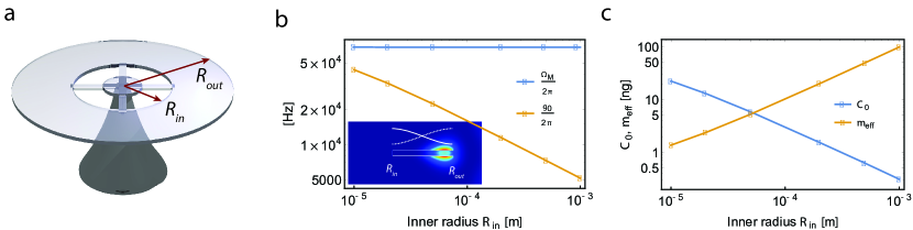
Here we consider the case of a third sound wave confined on the surface of an annular disk resonator, as illustrated in Fig. 5(a). In this case, the surface deformation profile is given by: [57]
| (15) |
where and are respectively the azimuthal and radial mode numbers, and mode amplitude coefficients and and respectively the Bessel functions of the first and second kind of order . For the free-free boundary condition in and , the wavenumber is defined as the root of the equation:
| (16) |
and the coefficients A and B are found by imposing the free boundary conditions in and (i.e. ). Following the same approach outlined in the main text, we numerically calculate the values of and as a function of resonator dimensions for the annular disk case. This is shown in Fig. 5(b), where is swept from m to 1 mm, while the annulus width () is kept constant at 4 microns. As the third sound frequency only depends on the annular width, remains constant over the entire range (blue line). For a fixed annular width, increasing results in the effective mass increasing nearly linearly (simply as the resonator surface area), resulting in a much less dramatic decrease in with resonator radius when compared to the disk case (see Fig. 4), with for example kHz on millimeter-sized annular resonators. Fig. 5(c) plots the dependence of and over the same parameter range. The predicted value of assumes a constant and , as in the disk case (see section 4.2), and reaches 22 for the smallest resonators.
7 Appendix B: Microsphere resonator
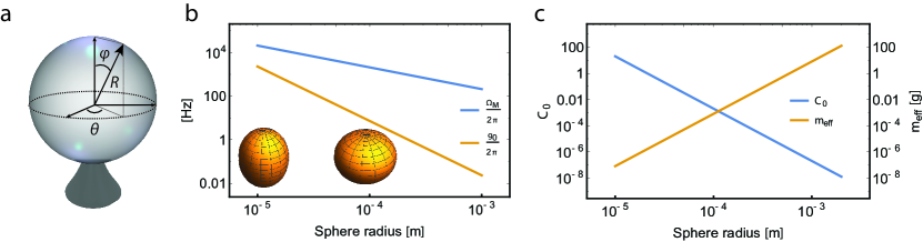
Here we briefly address the optomechanical coupling between third sound and light respectively confined on the surface of and inside a microsphere resonator [58, 22], see Fig. 6(a). In analogy to the disk case, we model the third sound mode profile on a sphere as:
| (17) |
with the mode amplitude and the Laplace spherical harmonic of degree and order , solution to Laplace’s equation on a sphere. Following the same treatment outlined in section 3.2, we derive the effective mass of a point situated on the sphere’s equator ():
| (18) |
Which, substituting , for a mode rotationally invariant along simplifies to:
| (19) |
Here we recognize the same effective mass scaling as in the disk case (see Eq. 13). Next, as discussed in section 2, we set and use this approximation to calculate the optomechanical coupling rate . This is shown in Fig. 6(b) for the (=2; =0) third sound mode. This mode corresponds to the superfluid sloshing back and forth between the equator and the poles, as illustrated in the inset, and naturally exhibits good optomechanical coupling to a WGM localized on the sphere’s equator. As in the case of a disk resonator, scales as 1/ and scales as ; however the dependence of on is even steeper than in the disk case, since for a sphere is also inversely proportional to . For a sphere of radius microns and a 30 nm thick film, Hz, approximately 28 times less than for the (=0; =1) mode of a disk of identical radius (see Fig. 4(b)). This smaller value has two distinct origins: a times smaller for the third sound mode on the sphere, because of its larger effective mass, and a times smaller G compared to the disk case because of the weaker interaction between the superfluid film and the WGM in the sphere, as discussed in section 2. Finally Fig. 6(c) plots the dependence of and on sphere radius, for a 30 nm thick superfluid film. The predicted value of assumes a constant and [58]. This plot underscores the strong dependence of with sphere radius: as R goes from 10 microns to 2 mm, spans over 9 orders of magnitude. For mm, reaches 130 g, i.e. over times the actual mass of the superfluid film.
References
- [1] Markus Aspelmeyer, Tobias J. Kippenberg, and Florian Marquardt. Cavity optomechanics. Reviews of Modern Physics, 86(4):1391–1452, December 2014.
- [2] Jasper Chan, T. P. Mayer Alegre, Amir H. Safavi-Naeini, Jeff T. Hill, Alex Krause, Simon Gröblacher, Markus Aspelmeyer, and Oskar Painter. Laser cooling of a nanomechanical oscillator into its quantum ground state. Nature, 478(7367):89–92, October 2011.
- [3] E. E. Wollman, C. U. Lei, A. J. Weinstein, J. Suh, A. Kronwald, F. Marquardt, A. A. Clerk, and K. C. Schwab. Quantum squeezing of motion in a mechanical resonator. Science, 349(6251):952–955, August 2015.
- [4] Gaurav Bahl, Kyu Hyun Kim, Wonsuk Lee, Jing Liu, Xudong Fan, and Tal Carmon. Brillouin cavity optomechanics with microfluidic devices. Nature communications, 4, 2013.
- [5] E. Gil-Santos, C. Baker, D. T. Nguyen, W. Hease, C. Gomez, A. Lemaître, S. Ducci, G. Leo, and I. Favero. High-frequency nano-optomechanical disk resonators in liquids. Nature Nanotechnology, 10(9):810–816, September 2015.
- [6] King Yan Fong, Menno Poot, and Hong X Tang. Nano-optomechanical resonators in microfluidics. Nano letters, 15(9):6116–6120, 2015.
- [7] Raphael Dahan, Leopoldo L. Martin, and Tal Carmon. Droplet optomechanics. Optica, 3(2):175, February 2016.
- [8] G. M. Seidel, R. E. Lanou, and W. Yao. Rayleigh scattering in rare-gas liquids. Nuclear Instruments and Methods in Physics Research Section A: Accelerators, Spectrometers, Detectors and Associated Equipment, 489(1–3):189–194, August 2002.
- [9] L. A. De Lorenzo and K. C. Schwab. Superfluid optomechanics: coupling of a superfluid to a superconducting condensate. New Journal of Physics, 16(11):113020, November 2014.
- [10] David R Tilley and John Tilley. Superfluidity and superconductivity. CRC Press, 1990.
- [11] X. Rojas and J. P. Davis. Superfluid nanomechanical resonator for quantum nanofluidics. Physical Review B, 91(2):024503, January 2015.
- [12] A. D. Kashkanova, A. B. Shkarin, C. D. Brown, N. E. Flowers-Jacobs, L. Childress, S. W. Hoch, L. Hohmann, K. Ott, J. Reichel, and J. G. E. Harris. Superfluid Brillouin Optomechanics. arXiv:1602.05640 [physics, physics:quant-ph], February 2016. arXiv: 1602.05640.
- [13] G. I. Harris, D. L. McAuslan, E. Sheridan, Y. Sachkou, C. Baker, and W. P. Bowen. Laser cooling and control of excitations in superfluid helium. Nature Physics, 12(8):788–793, August 2016.
- [14] D. L. McAuslan, G. I. Harris, C. Baker, Y. Sachkou, X. He, E. Sheridan, and W. P. Bowen. Microphotonic Forces from Superfluid Flow. Physical Review X, 6(2):021012, April 2016.
- [15] K. R. Atkins. Third and Fourth Sound in Liquid Helium II. Physical Review, 113(4):962–965, February 1959.
- [16] J. H. Scholtz, E. O. McLean, and I. Rudnick. Third Sound and the Healing Length of He II in Films as Thin as 2.1 Atomic Layers. Physical Review Letters, 32(4):147–151, January 1974.
- [17] E. J. Yarmchuk, M. J. V. Gordon, and R. E. Packard. Observation of Stationary Vortex Arrays in Rotating Superfluid Helium. Physical Review Letters, 43(3):214–217, July 1979.
- [18] F. M. Ellis and L. Li. Quantum swirling of superfluid helium films. Physical review letters, 71(10):1577, 1993.
- [19] Luis F. Gomez, Ken R. Ferguson, James P. Cryan, Camila Bacellar, Rico Mayro P. Tanyag, Curtis Jones, Sebastian Schorb, Denis Anielski, Ali Belkacem, Charles Bernando, Rebecca Boll, John Bozek, Sebastian Carron, Gang Chen, Tjark Delmas, Lars Englert, Sascha W. Epp, Benjamin Erk, Lutz Foucar, Robert Hartmann, Alexander Hexemer, Martin Huth, Justin Kwok, Stephen R. Leone, Jonathan H. S. Ma, Filipe R. N. C. Maia, Erik Malmerberg, Stefano Marchesini, Daniel M. Neumark, Billy Poon, James Prell, Daniel Rolles, Benedikt Rudek, Artem Rudenko, Martin Seifrid, Katrin R. Siefermann, Felix P. Sturm, Michele Swiggers, Joachim Ullrich, Fabian Weise, Petrus Zwart, Christoph Bostedt, Oliver Gessner, and Andrey F. Vilesov. Shapes and vorticities of superfluid helium nanodroplets. Science, 345(6199):906–909, August 2014.
- [20] Enrico Fonda, David P. Meichle, Nicholas T. Ouellette, Sahand Hormoz, and Daniel P. Lathrop. Direct observation of Kelvin waves excited by quantized vortex reconnection. Proceedings of the National Academy of Sciences, 111(Supplement 1):4707–4710, March 2014.
- [21] Ge Yang, A. Fragner, G. Koolstra, L. Ocola, D. A. Czaplewski, R. J. Schoelkopf, and D. I. Schuster. Coupling an Ensemble of Electrons on Superfluid Helium to a Superconducting Circuit. Physical Review X, 6(1):011031, March 2016.
- [22] A. B. Matsko and V. S. Ilchenko. Optical resonators with whispering-gallery modes-part I: basics. IEEE Journal of Selected Topics in Quantum Electronics, 12(1):3–14, January 2006.
- [23] C. W. F. Everitt, K. R. Atkins, and A. Denenstein. Detection of Third Sound in Liquid Helium Films. Physical Review Letters, 8(4):161–163, February 1962.
- [24] A. M. R. Schechter, R. W. Simmonds, R. E. Packard, and J. C. Davis. Observation of ‘third sound’ in superfluid 3He. Nature, 396(6711):554–557, December 1998.
- [25] G. Anetsberger, O. Arcizet, Q. P. Unterreithmeier, R. Rivière, A. Schliesser, E. M. Weig, J. P. Kotthaus, and T. J. Kippenberg. Near-field cavity optomechanics with nanomechanical oscillators. Nature Physics, 5(12):909–914, December 2009.
- [26] Russell J. Donnelly and Carlo F. Barenghi. The Observed Properties of Liquid Helium at the Saturated Vapor Pressure. J. Phys. Chem. Ref. Data, 27(6):1217–1274, November 1998.
- [27] Emmanuel Rosencher and Borge Vinter. Optoelectronics. Cambridge University Press, 2002.
- [28] T. J. Kippenberg, S. M. Spillane, D. K. Armani, and K. J. Vahala. Fabrication and coupling to planar high-Q silica disk microcavities. Applied Physics Letters, 83(4):797–799, July 2003.
- [29] Matthew Borselli, Thomas J. Johnson, and Oskar Painter. Beyond the Rayleigh scattering limit in high-Q silicon microdisks: theory and experiment. Optics Express, 13(5):1515, 2005.
- [30] Warwick P Bowen and Gerard J Milburn. Quantum optomechanics. CRC Press, 2015.
- [31] Christopher Baker, William Hease, Dac-Trung Nguyen, Alessio Andronico, Sara Ducci, Giuseppe Leo, and Ivan Favero. Photoelastic coupling in gallium arsenide optomechanical disk resonators. Optics Express, 22(12):14072–14086, June 2014.
- [32] Xiaoshun Jiang, Qiang Lin, Jessie Rosenberg, Kerry Vahala, and Oskar Painter. High-Q double-disk microcavities for cavity optomechanics. Optics Express, 17(23):20911–20919, November 2009.
- [33] Ivan Favero, Sebastian Stapfner, David Hunger, Philipp Paulitschke, Jakob Reichel, Heribert Lorenz, Eva M. Weig, and Khaled Karrai. Fluctuating nanomechanical system in a high finesse optical microcavity. Optics express, 17(15):12813–12820, 2009.
- [34] Robin M Cole, George A Brawley, Vivekananda P Adiga, Roberto De Alba, Jeevak M Parpia, Bojan Ilic, Harold G Craighead, and Warwick P Bowen. Evanescent-field optical readout of graphene mechanical motion at room temperature. Physical Review Applied, 3(2):024004, 2015.
- [35] R. Schilling, H. Schütz, A. H. Ghadimi, V. Sudhir, D. J. Wilson, and T. J. Kippenberg. Near-Field Integration of a SiN Nanobeam and a Microcavity for Heisenberg-Limited Displacement Sensing. Physical Review Applied, 5(5):054019, May 2016.
- [36] Lu Ding, Christophe Baker, Pascale Senellart, Aristide Lemaitre, Sara Ducci, Giuseppe Leo, and Ivan Favero. High frequency gaas nano-optomechanical disk resonator. Physical review letters, 105(26):263903, 2010.
- [37] E. S. Sabisky and C. H. Anderson. Verification of the Lifshitz Theory of the van der Waals Potential Using Liquid-Helium Films. Physical Review A, 7(2):790–806, February 1973.
- [38] W. E. Keller. Thickness of the Static and the Moving Saturated He II Film. Physical Review Letters, 24(11):569–573, March 1970.
- [39] F. M. Ellis and Hai Luo. Observation of the persistent-current splitting of a third-sound resonator. Physical Review B, 39(4):2703, 1989.
- [40] Owen M Phillips. The Dynamics of the Upper Ocean. Cambridge University Press, London, 1969.
- [41] Christian Enss and Siegfried Hunklinger. Low-Temperature Physics. Springer, April 2005.
- [42] E. S. Sabisky and C. H. Anderson. Onset for Superfluid Flow in Films on a Variety of Substrates. Physical Review Letters, 30(22):1122–1125, May 1973.
- [43] Andrew Schechter. Third Sound in Superfluid 3He. PhD thesis, 1999.
- [44] A. Vorontsov and J. A. Sauls. Spectrum of Third Sound Cavity Modes on Superfluid 3. Journal of Low Temperature Physics, 134(3-4):1001–1008, 2004.
- [45] P. J. Shirron and M. J. DiPirro. Suppression of superfluid film flow in the XRS helium dewar. In Advances in cryogenic engineering, pages 949–956. Springer, 1998.
- [46] Laszlo Tisza. The theory of liquid helium. Physical Review, 72(9):838, 1947.
- [47] Jing Wang, Zeying Ren, and Clark TC Nguyen. 1.156-GHz self-aligned vibrating micromechanical disk resonator. IEEE Trans. Ultrason., Ferroelect., Freq. Control, 51(12):1607–1628, 2004.
- [48] Mingyun Yuan, Vibhor Singh, Yaroslav M. Blanter, and Gary A. Steele. Large cooperativity and microkelvin cooling with a three-dimensional optomechanical cavity. Nature Communications, 6:8491, October 2015.
- [49] Kwan Lee, Terry McRae, Glen Harris, Joachim Knittel, and Warwick Bowen. Cooling and Control of a Cavity Optoelectromechanical System. Physical Review Letters, 104(12):123604, March 2010.
- [50] Xiankai Sun, Xufeng Zhang, and Hong X. Tang. High-Q silicon optomechanical microdisk resonators at gigahertz frequencies. Applied Physics Letters, 100(17):173116, 2012.
- [51] L. Ding, C. Baker, P. Senellart, A. Lemaitre, S. Ducci, G. Leo, and I. Favero. Wavelength-sized GaAs optomechanical resonators with gigahertz frequency. Applied Physics Letters, 98(11):113108, 2011.
- [52] David Parrain, Christophe Baker, Guillaume Wang, Biswarup Guha, Eduardo Gil Santos, Aristide Lemaitre, Pascale Senellart, Giuseppe Leo, Sara Ducci, and Ivan Favero. Origin of optical losses in gallium arsenide disk whispering gallery resonators. Optics Express, 23(15):19656, July 2015.
- [53] D. T. Ekholm and R. B. Hallock. Studies of the decay of persistent currents in unsaturated films of superfluid . Physical Review B, 21(9):3902–3912, May 1980.
- [54] Y Sato and R E Packard. Superfluid helium quantum interference devices: physics and applications. Reports on Progress in Physics, 75(1):016401, January 2012.
- [55] A. Nunnenkamp, K. Børkje, and S. M. Girvin. Single-Photon Optomechanics. Physical Review Letters, 107(6):063602, August 2011.
- [56] H. X. Tang and D. Vitali. Prospect of detecting single-photon-force effects in cavity optomechanics. Physical Review A, 89(6):063821, June 2014.
- [57] H. P. W. Gottlieb. Harmonic properties of the annular membrane. The Journal of the Acoustical Society of America, 66(3):647–650, September 1979.
- [58] D. W. Vernooy, Vladimir S. Ilchenko, H. Mabuchi, E. W. Streed, and H. J. Kimble. High-Q measurements of fused-silica microspheres in the near infrared. Optics Letters, 23(4):247–249, 1998.