Focusing characteristics of a 4 parabolic mirror light-matter interface
Abstract
Focusing with a 4 parabolic mirror allows for concentrating light from nearly the complete solid angle, whereas focusing with a single microscope objective limits the angle cone used for focusing to half solid angle at maximum. Increasing the solid angle by using deep parabolic mirrors comes at the cost of adding more complexity to the mirror’s fabrication process and might introduce errors that reduce the focusing quality. To determine these errors, we experimentally examine the focusing properties of a 4 parabolic mirror that was produced by single-point diamond turning. The properties are characterized with a single 174Yb+ ion as a mobile point scatterer. The ion is trapped in a vacuum environment with a movable high optical access Paul trap. We demonstrate an effective focal spot size of 209 nm in lateral and 551 nm in axial direction. Such tight focusing allows us to build an efficient light-matter interface. Our findings agree with numerical simulations incorporating a finite ion temperature and interferometrically measured wavefront aberrations induced by the parabolic mirror. We point at further technological improvements and discuss the general scope of applications of a 4 parabolic mirror.
I Introduction
Free space interaction between light and matter is incorporated as a key technology in many fields in modern science. The efficiency of interaction influences measurements and applications ranging from various kinds of fundamental research to industrial applications. New innovations and new types of high precision measurements can be triggered by improving the tools needed for a light-matter interface. To achieve high interaction probability with a focused light field in free space, an experimental scheme using parabolic mirrors for focusing onto single atoms has been developed in recent years Quabis et al. (2000); Sondermann et al. (2007); Stobińska et al. (2009). This scheme relies on mode matching of the focused radiation to an electric dipole mode (cf. Ref. Leuchs and Sondermann (2013) and citations therein).
Focusing in free-space experiments is usually done with state-of-the-art lens based imaging systems Piro et al. (2011); Tey et al. (2009a); Wrigge et al. (2008); Pinotsi and Imamoglu (2008). Single lenses, however, suffer from inherent drawbacks like dispersion induced chromatic aberrations, optical aberrations, and auto-fluorescence, respectively. Most of these limitations can be corrected to a high degree by precisely assembling several coated lenses in a lens-system, e.g. in a high numerical aperture (NA) objective. Although solving some problems, multi-lens-systems induce new problems such as short working distances, low transmission for parts of the optical spectrum, the need for immersion fluids, and high costs, respectively. Therefore, multi-lens systems are often application specific providing best performance only for the demands that are most important for the application.
Mirror based objectives are an alternative to lens-based systems and can overcome some of these problems. The improvement is based on a mirror’s inherent property of being free from chromatic aberrations. The nearly wavelength independent behavior also leads to a homogeneous reflectivity for a large spectral window. Comparing the reflectivity of mirrors to the transmission of lens based objectives, mirrors can sometimes also surpass lens-based systems. But surprisingly, they are rarely used when high interaction efficiency is required. This lack in application may be due to the fact that reflecting imaging systems, like the Cassegrain reflector, cannot provide a high NA. A high NA is however needed for matching the emission pattern of a dipole, which spans over the entire solid angle. The limitation in NA consequently constitutes a limitation in the maximum achievable light-matter coupling efficiency.
High NA parabolic mirrors (NA = 0.999) have meanwhile been successfully applied as objectives in confocal microscopy Drechsler et al. (2001); Stadler et al. (2008), demonstrating the potential for imaging applications. The parabolic mirror (PM) is a single optical element that, in theory, can cover nearly the complete 4 solid angle for tight focusing Lindlein et al. (2007). In this article we report on the detailed characterization of such a 4 parabolic mirror (4-PM), in which we sample the focal intensity distribution with a single 174Yb+ ion, trapped in a stylus like movable Paul trap Maiwald et al. (2009).
In contrast to our previous studies Fischer et al. (2014), we measure the response of the ion at a wavelength different to the one used for excitation. This approach is standard in fluorescence microscopy and has also been used in experiments with trapped ions Linke et al. (2012). It renders unnecessary a spatial separation of focused light and light scattered by the ion, thus lifting the limitation of focusing only from half solid angle as in Ref. Fischer et al. (2014). However, we will find below that by using the solid angle provided by our 4-PM the measured effective excitation point spread function (PSF) is worse when using the full mirror as compared to focusing from only half solid angle. As outlined below, this is not a general restriction but specific to the aberrations of the mirror used in our experiments. It is a challenge to determine the aberrations of such a deep parabolic mirror Leuchs et al. (2008) and we discovered the full extent of these aberrations only when scanning the 3D field distribution with the single ion, revealing an error in the earlier interferometric measurements. Here, we present a reasonable agreement of the experiments with results of simulations incorporating a finite ion temperature and new interferometrically measured wavefront aberrations of the parabolic mirror itself.
Despite of these aberrations, the efficiency obtained here for coupling the focused light to the linear dipole transition of the 174Yb+ ion is better than reported previously Fischer et al. (2014), using the full mirror as well as focusing from half solid angle. As a further improvement in comparison to Ref. Fischer et al. (2014) we keep the excitation of the ion well below saturation making sure that the size of the ion’s wave function stays approximately constant as much as possible. All in all, the ion constitutes a nanoscopic probe with well defined properties throughout the measurement range.
In the concluding discussion of this paper, the parabolic mirror is compared to other high NA focusing tools, especially to lens-based 4 microscopes. Its possible field of application is discussed and further improvements to the existing set-up are proposed.
II Setup and experiment
Our main experimental intention is to focus light to a minimal spot size in all spatial directions simultaneously. The highest electric energy density that can be realized with any focusing optics is created by an electric dipole wave Bassett (1986). We therefore choose this type of spatial mode in our experiment. The electric dipole wave is created by first converting a linear polarized Gaussian beam into a radially polarized donut mode via a segmented half-wave plate (B- Halle) Quabis et al. (2005); Golla et al. (2012). Second, the radially polarized donut mode is focused with a parabolic mirror onto the trapped ion. This, in theory, enables us to convert approximately of the donut mode into a linear dipole mode Sondermann et al. (2008). The conversion efficiency is limited since the donut mode is only approximating the ideal spatial mode that is necessary to create a purely linear dipole mode Sondermann et al. (2007); Alber et al. (2013) by being focused with the parabolic mirror. The donut mode, however, yields the experimental advantage of being propagation invariant and comparably easy to generate.
Our focusing tool, the parabolic mirror, is made of diamond turned aluminum (Fraunhofer Institute for Applied Optics and Precision Engineering, Jena) with a reflectivity of 64 % for the incident mode at a wavelength of nm. Its geometry has a focal length of 2.1 mm and an outer aperture of 20 mm in diameter. In total, the geometry covers 81 % of the complete solid angle. This fraction corresponds to 94 % of the solid angle that is relevant for coupling to a linear dipole oriented along the axis of symmetry Sondermann et al. (2008); Lindlein et al. (2007). Furthermore, the mirror has three bores near its vertex: two bores with a diameter of 0.5 mm for dispensing neutral atoms and for illuminating the ion with additional laser beams, respectively; and one bore with a diameter of 1.5 mm for the ion trap itself. The ion trap is a Stylus-like Paul trap similar to Maiwald et al. (2009) with high optical access. The trap is mounted on a movable xyz piezo translation stage (PIHera P-622K058, Physik Instrumente) that is used for measuring the effective excitation PSF. The effective excitation PSF is defined as the convolution of the focal intensity distribution with the spatial extent of the ion.
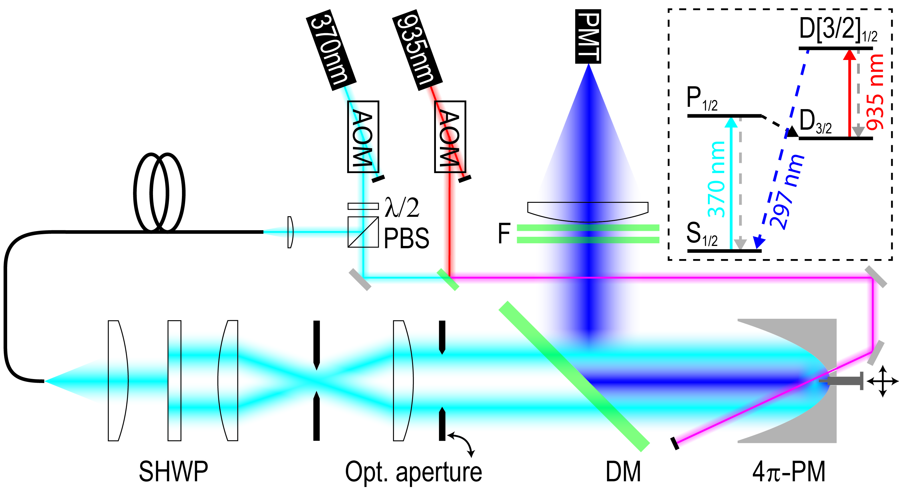
We measure the effective excitation PSF by probing the focal spot at different positions. In order to do so, we use the translation stage to scan the ion through the focal spot with an increment of 25 nm. At each position, the incoming dipole mode excites the transition that has a wavelength of nm and a transition linewidth of MHz Meyer et al. (2012). The relevant energy levels of are shown in figure 1. We weakly drive this transition such that the probability for exciting the ion into the state is proportional to the electric energy density at any point in the focal area. During these measurements, the ion is Doppler cooled by the focused donut mode. Hence, the detuning of this mode relative to the transition and its power determine the temperature of the ion, see appendix for further details.
| Transition | Branching ratio | Decay rate [] |
|---|---|---|
| MHz | ||
| MHz | ||
| Hz |
Since we excite the ion from the complete solid angle that is covered by the 4 parabolic mirror and since almost all excitation light is reflected into the detection beam path by the parabolic mirror, we cannot directly detect the fluorescent response of the ion at the same wavelength. Instead, we detect photons at a wavelength of nm allowing us to independently focus and detect from nearly the complete solid angle. Photons at the detection wavelength are emitted during the spontaneous decay Meyer et al. (2012). The level is populated when the ion spontaneously decays from the excited state into the metastable state (branching ratio , lifetime of 52 ms Olmschenk et al. (2007), see table 1). From this state, we optically pump the ion into the state by saturating the transition with a strong laser field at a wavelength of 935.2 nm (DL-100, Toptica Photonics). The upper state of this transition decays to the ground state with a probability of 98 % Meyer et al. (2012). The infrared laser is co-aligned with a second laser at the excitation wavelength (TA-SHG pro, Toptica Photonics) and both are sent through the focus of the parabolic mirror via one of its backside bores (see figure 1). The second laser at the excitation wavelength is used for ionization.
The emitted fluorescent photons at the detection wavelength are out-coupled from the excitation beam path via a dichroic mirror (FF310-Di01, Semrock) and two clean up filters (FF01-292/27-25, Semrock). Afterwards, we detect them with a photomultiplier tube in Geiger mode operation (MP-942, Perkin Elmer) that has a remaining underground/dark count rate of 10 - 20 cps. The overall detection efficiency at the detection wavelength was measured via pulsed excitation and amounts to (see appendix). The detection efficiency is needed for the determination of the coupling efficiency to the trapped ion.
Based on the atomic decay rate on the detected transition, the total photon emission rate would be approximately R = for (see equation 1). Taking into account the finite detection efficiency, we would expect to measure approximately .
The coupling efficiency is measured by recording the detection count rate as a function of the excitation power . Analyzing the four-level quantum master equation we find that both quantities are proportional to each other in the limit of strong repumping powers and saturation parameters . The latter condition is met by keeping in our measurements. This also ensures that the spatial extent of the ion is approximately constant throughout the measurement, see appendix. The dependence of for varying excitation power is given by
| (1) |
with denoting the saturation parameter, and the coupling efficiency, respectively. The saturation power is defined as . The factor accounts for the fact that we are not driving a closed linear-dipole transition but a J=1/2 J=1/2 one. The relation between saturation parameter, saturation power and coupling efficiency is Fischer et al. (2014). is the detuning of the excitation laser from the resonance. The formula for the detection count rate enables us to determine the coupling efficiency by curve fitting of our measured data for as a function of . For the curve fitting, all parameters except the coupling efficiency are kept constant. During the measurement of the coupling efficiency, we position the ion exactly in the maximum of the excitation PSF, i.e. we measure the maximum coupling efficiency obtainable in the focal region under the current experimental conditions.
III Results
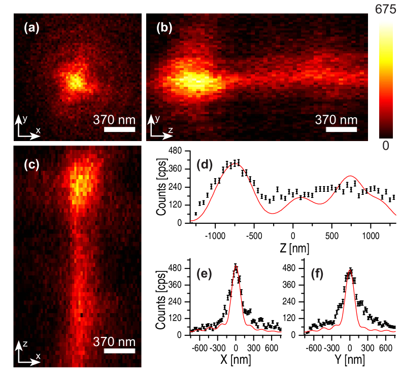

The experimental results for the effective excitation PSF are shown in figure 2. We measure a spot size of nm (FWHM) in the lateral direction (a, e, f). In the axial direction (b - d), however, the focal peak is broadened due to optical aberrations. The influence of the aberrations is reduced, when we limit the front aperture of the 4-PM to half solid angle (figure 3). The reduced aperture results in a lateral width of nm and an axial width of nm. These values include the influence of the finite spatial extent of the trapped ion (see appendix). In the Doppler limit, this extent is approximately 140 nm in lateral and 80 nm in axial direction considering the trap frequencies kHz and kHz, respectively, and a detuning from resonance of about 14.1 MHz.
To determine the minimal contribution of the ion-size to the focal broadening when Doppler cooling, we simulate the excitation PSF based on a generalization of the method presented in Richards and Wolf (1959). Our simulation also includes the aberrations of the parabolic mirror which were measured interferometrically beforehand Leuchs et al. (2008). The intensity distributions resulting from simulations only accounting for mirror aberrations are subsequently convolved with the spatial extent of the ion to achieve the effective excitation PSF.
| Simulation | Lateral | Axial | |||
|---|---|---|---|---|---|
| HSA | FSA | HSA | FSA | ||
| Exc. PSF | ideal mirror (i.m.) | 139 nm | 142 nm | 412 nm | 253 nm |
| aberrated mirror (a.m.) | 135 nm | 135 nm | 536 nm | ||
| i.m. with ion-extent | 189 nm | 192 nm | 418 nm | 266 nm | |
| a.m. with ion-extent | 189 nm | 189 nm | 542 nm | ||
| Eff. exc. PSF (measurement) | nm | nm | nm | ||
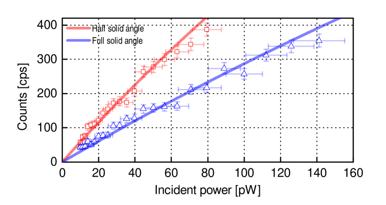
The outcomes of our simulations are shown in table 2. The effective PSF obtained in the simulations exhibits a good qualitative agreement with the PSF obtained in the experiment, cf. figure 2 and 3. Based on these results, the coupling efficiency is expected (see appendix) to be for illuminating the full aperture and for limiting the aperture of the 4-PM to half solid angle. From the data shown in figure 4, we measure a coupling efficiency of (full solid angle) and (half solid angle). These values are close to the expected values from the simulations taking into account all current deficiencies of the set-up.
IV Discussion
Concentration of light into a narrow three dimensional volume is involved in many scientific applications. The scope ranges from applications that require ”classical” light fields, like light microscopy, optical traps and material processing, to applications in quantum information science. In quantum information science, tight focusing of light is the key ingredient for free-space light-matter interfaces with a high coupling efficiency. This kind of free-space set-up may be an alternative to cavity based light-matter interfaces also providing high interaction strength. But in contrast to cavity assisted set-ups, free-space experiments often have a low level of instrument complexity and provide higher bandwidth. This is important considering the scalability and flexibility of an experimental set-up.
Technically, concentration of light is done by using focusing optics. How tight the focusing will be, depends on the numerical aperture of the focusing optics that is given by , where is the half-opening angle of the optics’ aperture and is the refractive index of the surrounding medium. For high NA objectives, the exact dependence of the focal volume as a function of NA can only be calculated numerically incorporating a vectorial treatment of the electric field. But as the numerical aperture increases, the focal volume will basically decrease.
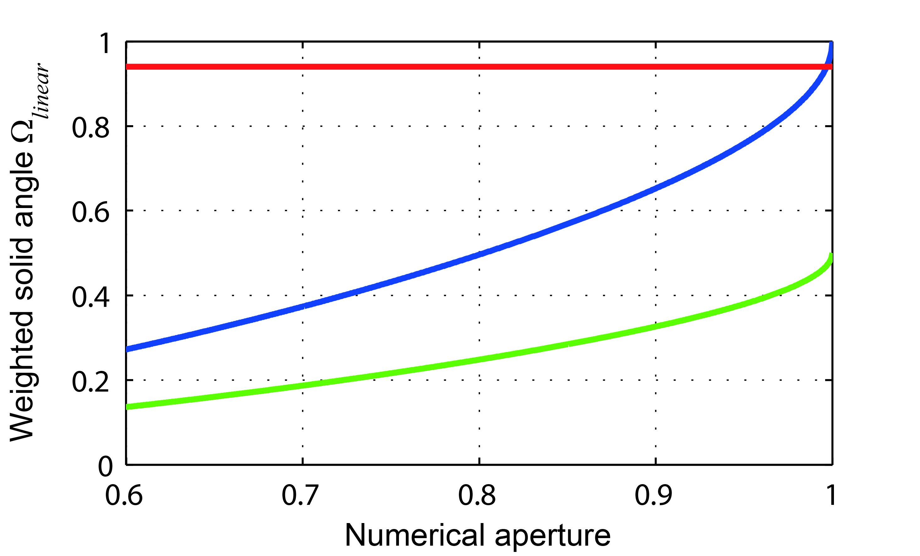
For a 4 focusing optic, the numerical aperture is no longer defined. Nevertheless, it seems obvious that diffraction limited focusing from more than half of the hemisphere would produce a smaller three-dimensional focal volume. Consequently, a different quantity has to be used for comparing the performance of different 4 focusing optics. One suitable quantity is the weighted solid angle (normalized to ) Sondermann et al. (2008). It is the solid angle that is covered by the focusing optics weighted by the dipole’s angular irradiance pattern. defines the maximum fraction of incident power that can be coupled into the dipole mode of a single emitter. Consequently, it provides information about the ability to concentrate light since an electric dipole mode achieves the highest possible energy concentration Bassett (1986). therefore means, that all of the light is coupled into the dipole mode, assuming the ideal radiation pattern. The focusing capabilities of such a focusing optics can not be exceeded by any other optics. In figure 5, the maximal conversion efficiency into a linear dipole wave is compared for different (4) focusing systems also including the 4-PM geometry used in the experiment. In case of our 4-PM, one has . The same fraction of the weighted solid angle can be covered using two opposing objective lenses each having a NA of 0.997 in vacuum. High quality objectives of such high numerical aperture are, however, not available.
In the experiment, the weighted solid angle covered by the focusing optics is one quantity that determines the measured light-matter coupling efficiency. Other important experimental factors are the optical aberrations and the spatial extent of the ion, respectively. Under ideal conditions, we expect a coupling efficiency of where is the field overlap with the ideal dipole mode Golla et al. (2012). But in our measurements, we are not able to reach this limit. Our numerical simulations imply, however, that we are currently not primarily limited by the covered solid angle, but by the spatial extent of the ion and the optical aberrations (see table 2). The optical aberrations reduce the Strehl ratios for focusing from full solid angle and half solid angle to a different degree, see Appendix for details. Since the Strehl ratio is by far worse in the case of full solid angle illumination, the half solid angle focusing yields the better coupling efficiency. The measured coupling efficiency is, however, approximately twice as high as measured with our setup in half solid angle configuration previously Fischer et al. (2014). We conjecture that this is due to the fact that here we do not fit a full saturation curve but restrict the experiment to low saturation parameters, preventing an increase of the ion’s spread in position space and the associated stronger averaging over the focal intensity distribution. This effect was not considered in Ref. Fischer et al. (2014). Therefore, it is possible that the increase of the ion’s extent at higher excitation powers has affected the saturation of the ion there, resulting in a larger saturation power and thus a seemingly smaller coupling efficiency. Furthermore, part of the improvement might be attributed to a better preparation of the incident beam.
Enhancing the optical properties of our focusing system and therefore also the coupling efficiency can be done by correcting for the aberrations over the full aperture. The predominant aberrations in our set-up are due to form deviations of the mirror from the ideal parabolic shape. A higher degree of form accuracy could be provided by including interferometric measurement techniques Leuchs et al. (2008) into the mirror’s production process. Alternatively, the aberrations can be corrected by preshaping the incident wavefront before it enters the parabolic mirror. Wavefront shaping techniques may rely on adaptive optical elements (e.g. liquid crystal display, deformable mirror) or a (gray tone) phase plate. The latter technique has already been tested for a 4-PM of the same geometry as used here Golla et al. (2012). Involving a second optical element for wavefront correction in front of the parabolic mirror would only slightly add complexity to the system. If the corrective element is reflection and refraction based, like a continuous membrane deformable mirror is, the wavelength-independent character of the imaging system is retained.
The wavelength-independent character is the reason why the 4-PM is intrinsically free of chromatic aberrations. This is beneficial for applications that require tight focusing not only for a monochromatic light source. Typical applications can be found in the field of microscopy: Confocal fluorescence microscopy Sheppard and Choudhury (1977) usually requires correction for the excitation and the detection wavelength; RESOLFT-type far-field Nanoscopy Hell (2007) in addition requires correction for the depletion beam. Further examples are two- and three-photon microscopy Horton et al. (2013); Denk et al. (1990) or Raman microscopy Andersen and Muggli (1981). The variety of reflective materials allows to specialize the 4-PM for a specific application, e.g. for high power applications, high sensitivity measurements or even for applications where wavelengths from the deep UV to the far IR are used at the same time. This ability may enable new illumination or imaging techniques that are not possible with today’s technology.
V Conclusion
We experimentally characterized a light-matter interface based on a 4-PM. By limiting its aperture, we could demonstrate an effective excitation PSF having a lateral spot size of nm in vacuum. That corresponds to . Using the full mirror we observed a strong splitting of the focal peak along the axial direction due to form deviations of the parabolic mirror. Measuring the induced aberrations interferometrically and including the results in numerical simulations yields values that are consistent with the experiment. In addition, we measured the light-matter coupling efficiency to be . This value is also in good agreement with our simulations. Our findings allow us to infer that we are currently limited by the aberrations of the parabolic mirror and the spatial extent of the ion.
We can surpass our current technical limitations by correcting the aberrations of the 4-PM. This would even further reduce the focal spot size and increase the coupling efficiency. Ways for wavefront correction were given in the discussion section of this work. We also may apply higher trap frequencies or ground state cooling techniques to reduce the spatial extent of the ion. Alternatively, we can trap doubly ionized Ytterbium in our experimental set-up Heugel et al. (2016). When trapping a ion we may not need to change the trapping or cooling techniques because the ion’s spatial extent is smaller in the Doppler limit (higher charge, narrower transition linewidth). Furthermore, provides a closed two-level transition that is desirable in many experiments on the fundamentals of light-matter interaction. This may be a path for realizing a set-up capable of reaching the ultimate limitations of focusing in free space Lindlein et al. (2007); Sondermann et al. (2007).
Acknowledgements
The authors thank S. Heugel, B. Srivathsan, I. Harder and M. Weber for fruitful discussions and M. Weber for valuable comments on the manuscript. G.L. acknowledges financial support from the European Research Council via the Advanced Grant ‘PACART’.
VI Appendix
Simulating the expected coupling efficiency
We simulate the focal intensity distribution along the principal axes of our system (x, y, z) based on a generalization of the method presented in Richards and Wolf (1959) including the aberrations of our parabolic mirror. The electric field, that the ion experiences is an average Tey et al. (2009b) over the electric field in the focus by the spread of the wavefunction of the ion due to its finite temperature. In order to calculate the expected effective PSF of the PM we convolve the simulated intensity distribution in the focus with the spatial extent of the ion along the corresponding trap axis. In order to deduce the coupling efficiency , we compare the resulting intensity in the focus to the one of a perfectly focused linear dipole wave Golla et al. (2012), with equal ingoing power, in all three directions. The product of these three ratios yields the expected .
Influence of the spatial extent of the ion’s wave function
For determining the spatial extent of the Doppler cooled ion, we assume it to be in a thermal state Eschner (2003). Hence the spatial extent in each dimension is described by a Gaussian shaped wave packet with width . The width can by calculated from the ground state wave packet by Eschner (2003)
where denotes the mean phonon number of the harmonic oscillator in -th direction and . is the ion’s mass and the trap frequency in direction . The probability for finding the ion at is hence described by
The mean phonon numbers are calculated using the semiclassical rate equations approach Stenholm (1986); Eschner et al. (2003). For the common case of cooling with laser beams impinging from small parts of the solid angle the average number of motional quanta along trap axis can, in the Lamb-Dicke regime, be approximated to be
| (2) |
where is the upper level population with respect to detuning and saturation parameter, the angle between the trap axis with the -vector of the laser beam, and a factor depending on the emission pattern of the ion. For ions the emission pattern is isotropic and therefore Stenholm (1986). In the case of cooling the ion with a dipole wave, the cooling mode has a continuous spectrum of -vectors, hence the factor determining the overlap of the beam and the trap axis has to be averaged over the incoming field linear dipole field, that is has the form . With the geometry of the trap and focusing employed in the setup described here, one of the trap axes is parallel to the optical axis of the mirror, while the other two are perpendicular. The mean overlap for these two cases, the averaged value of
| (3) |
with the integration along polar angle and azimuthal angle . This leads to a mean overlap of of the linear dipole mode with the axial trap axis and with the radial ones. For negligible excitation, a detuning of and the trap frequencies , , and , respectively, this yields , and . The trap frequencies are determined by applying an AC signal to one of the compensation electrodes and scanning the applied frequency over the frequency range supposed to contain the trap frequencies while monitoring the the rate of fluorescence photons.
We only use excitation powers such that . This equals a detection count rate of . For larger excitation powers, we expect the spatial extent of the ion to be comparable to the size of the focal intensity distribution and the coupling efficiency to be reduced. Since grows linearly with Chang et al. (2014), keeping ensures that the spatial extent of the ion is approximately constant over the whole measurement range. A change of in corresponds to a change of approximately in .
Interplay of mirror aberrations and focusing geometry
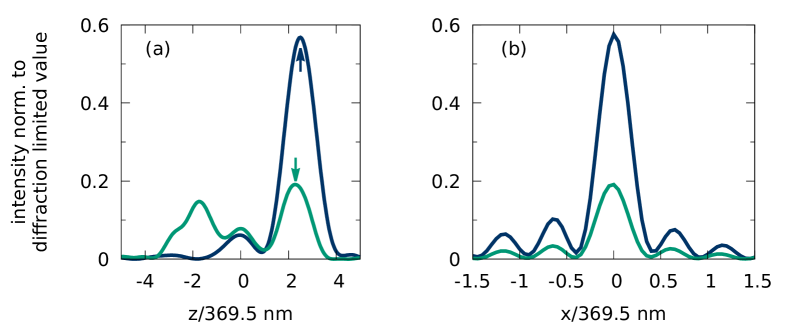
To clarify the reasons for the counter-intuitive finding of a larger coupling efficiency when focusing from only half solid angle, we discuss the influence of the mirror’s aberrations in more detail. Here, focusing from half solid angle means that no light is incident onto the parabolic mirror for radial distances to the optical axis larger than twice the focal length of the parabola. Figure 6 shows the results of simulations of the focal intensity distributions when only accounting for the aberrations of the parabolic mirror but neglecting the trapped ion’s wave function finite extent. For a parabolic mirror free of aberrations, i.e. a Strehl ratio of 1 no matter which portion of the mirror is used for focusing, one would expect coupling efficiencies of 90% when using the full mirror and 48% when focusing from half solid angle, assuming a mode overlap of in both cases. But as is apparent from the data in Fig. 6, the Strehl ratio drops by a factor of 3 when focusing with the full mirror in comparison to using only half of the solid angle for focusing. Therefore, the expected increase in coupling efficiency by focusing with the full mirror is hindered by the large decrease in Strehl ratio. This particular, device-specific distribution of the aberrations results in a larger coupling efficiency for the half-solid-angle case, as it is found in our experiments.
Determination of the detection efficiency
The main contributions to the detection efficiency are the reflectivity of the parabolic mirror for the detection mode, the quantum efficiency of the PMT, the covered solid angle of the parabolic mirror, the reflectivity of an additional beam splitter, the transmission of the dichroic mirror, and the transmission of the clean up filters, respectively. The reflectivity of the parabolic mirror and the quantum efficiency of the PMT are only known for a wavelength of 369.7 nm and amount to 67 % and 13 % Maiwald et al. (2012), respectively. We expect this value to be lower for the detection wavelength of 297.1 nm. Together with the covered solid angle of the parabolic mirror of 81 % Maiwald et al. (2012) and the polarization averaged design parameters for the beam splitter, dichroic mirror and the clean up filters of 43 %, the detection efficiency has to be lower than 3 %.
For a precise value, we additionally measure the detection efficiency via pulsed excitation. We pump the ion from the ground state into the metastable dark state by focusing a strong s long laser pulse at a wavelength of nm through the backside hole of the parabolic mirror. After that, we drive the transition with a strong laser pulse for about s to ensure that the decay takes place. During this decay, a photon at the detection wavelength of nm is emitted. While applying the infrared light, no UV light is driving the ion and only one detection photon can be emitted. For repeating the experiment with a pulse sequence rate of 10 kHz the background corrected count rate amounts to 142 cps. This yields the detection efficiency .
References
- Quabis et al. (2000) S. Quabis, R. Dorn, M. Eberler, O. Glöckl, and G. Leuchs, Optics Communications 179, 1 (2000).
- Sondermann et al. (2007) M. Sondermann, R. Maiwald, H. Konermann, N. Lindlein, U. Peschel, and G. Leuchs, Applied Physics B 89, 489 (2007).
- Stobińska et al. (2009) M. Stobińska, G. Alber, and G. Leuchs, EPL (Europhysics Letters) 86, 14007 (2009).
- Leuchs and Sondermann (2013) G. Leuchs and M. Sondermann, Journal of Modern Optics 60, 36 (2013), http://dx.doi.org/10.1080/09500340.2012.716461 .
- Piro et al. (2011) N. Piro, F. Rohde, C. Schuck, M. Almendros, J. Huwer, J. Ghosh, A. Haase, M. Hennrich, F. Dubin, and J. Eschner, Nat Phys 7, 17 (2011).
- Tey et al. (2009a) M. K. Tey, G. Maslennikov, T. C. H. Liew, S. A. Aljunid, F. Huber, B. Chng, Z. Chen, V. Scarani, and C. Kurtsiefer, New Journal of Physics 11, 043011 (2009a).
- Wrigge et al. (2008) G. Wrigge, I. Gerhardt, J. Hwang, G. Zumofen, and V. Sandoghdar, Nat Phys 4, 60 (2008).
- Pinotsi and Imamoglu (2008) D. Pinotsi and A. Imamoglu, Phys. Rev. Lett. 100, 093603 (2008).
- Drechsler et al. (2001) A. Drechsler, M. Lieb, C. Debus, A. Meixner, and G. Tarrach, Opt. Express 9, 637 (2001).
- Stadler et al. (2008) J. Stadler, C. Stanciu, C. Stupperich, and A. J. Meixner, Opt. Lett. 33, 681 (2008).
- Lindlein et al. (2007) N. Lindlein, R. Maiwald, H. Konermann, M. Sondermann, U. Peschel, and G. Leuchs, Laser Physics 17, 927 (2007).
- Maiwald et al. (2009) R. Maiwald, D. Leibfried, J. Britton, J. C. Bergquist, G. Leuchs, and D. J. Wineland, Nature Physics 5, 551 (2009).
- Fischer et al. (2014) M. Fischer, M. Bader, R. Maiwald, A. Golla, M. Sondermann, and G. Leuchs, Applied Physics B 117, 797 (2014).
- Linke et al. (2012) N. M. Linke, D. T. C. Allcock, D. J. Szwer, C. J. Ballance, T. P. Harty, H. A. Janacek, D. N. Stacey, A. M. Steane, and D. M. Lucas, Applied Physics B 107, 1175 (2012).
- Leuchs et al. (2008) G. Leuchs, K. Mantel, A. Berger, H. Konermann, M. Sondermann, U. Peschel, N. Lindlein, and J. Schwider, Applied Optics 47, 5570 (2008).
- Bassett (1986) I. M. Bassett, Optica Acta: International Journal of Optics 33, 279 (1986).
- Quabis et al. (2005) S. Quabis, R. Dorn, and G. Leuchs, Applied Physics B 81, 597 (2005).
- Golla et al. (2012) A. Golla, B. Chalopin, M. Bader, I. Harder, K. Mantel, R. Maiwald, N. Lindlein, M. Sondermann, and G. Leuchs, Eur. Phys. J. D 66, 190 (2012), arXiv:1207.3215 .
- Sondermann et al. (2008) M. Sondermann, N. Lindlein, and G. Leuchs, ArXiv e-prints (2008), arXiv:0811.2098 [physics.optics] .
- Alber et al. (2013) G. Alber, J. Z. Bernád, M. Stobińska, L. L. Sánchez-Soto, and G. Leuchs, Phys. Rev. A 88, 023825 (2013).
- Meyer et al. (2012) H. M. Meyer, M. Steiner, L. Ratschbacher, C. Zipkes, and M. Köhl, Physical Review A 85, 012502 (2012).
- Olmschenk et al. (2007) S. Olmschenk, K. C. Younge, D. L. Moehring, D. N. Matsukevich, P. Maunz, and C. Monroe, Physical Review A 76, 052314 (2007).
- Richards and Wolf (1959) B. Richards and E. Wolf, Proceedings of the Royal Society of London A: Mathematical, Physical and Engineering Sciences 253, 358 (1959).
- Sheppard and Choudhury (1977) C. J. R. Sheppard and A. Choudhury, Optica Acta: International Journal of Optics 24, 1051 (1977).
- Hell (2007) S. W. Hell, Science 316, 1153 (2007).
- Horton et al. (2013) N. G. Horton, K. Wang, D. Kobat, C. G. Clark, F. W. Wise, C. B. Schaffer, and C. Xu, Nature Photonics 7, 205 (2013).
- Denk et al. (1990) W. Denk, J. H. Strickler, and W. W. Webb, Science 248, 73 (1990).
- Andersen and Muggli (1981) M. E. Andersen and R. Z. Muggli, Analytical Chemistry 53, 1772 (1981), http://dx.doi.org/10.1021/ac00235a013 .
- Heugel et al. (2016) S. Heugel, M. Fischer, V. Elman, R. Maiwald, M. Sondermann, and G. Leuchs, Journal of Physics B: Atomic, Molecular and Optical Physics 49, 015002 (2016).
- Tey et al. (2009b) M. K. Tey, G. Maslennikov, T. C. H. Liew, S. A. Aljunid, F. Huber, B. Chng, Z. Chen, V. Scarani, and C. Kurtsiefer, New Journal of Physics 11, 043011 (2009b).
- Eschner (2003) J. Eschner, The European Physical Journal D 22, 341 (2003).
- Stenholm (1986) S. Stenholm, Rev. Mod. Phys. 58, 699 (1986).
- Eschner et al. (2003) J. Eschner, G. Morigi, F. Schmidt-Kaler, and R. Blatt, J. Opt. Soc. Am. B 20, 1003 (2003).
- Chang et al. (2014) R. Chang, A. L. Hoendervanger, Q. Bouton, Y. Fang, T. Klafka, K. Audo, A. Aspect, C. I. Westbrook, and D. Clément, Phys. Rev. A 90, 063407 (2014).
- Maiwald et al. (2012) R. Maiwald, A. Golla, M. Fischer, M. Bader, S. Heugel, B. Chalopin, M. Sondermann, and G. Leuchs, Physical Review A 86, 043431 (2012).