Simulation of the IEEE 1588 Precision Time Protocol in OMNeT++
Abstract
Real-time systems rely on a distributed global time base. As any physical clock device suffers from noise, it is necessary to provide some kind of clock synchronization to establish such a global time base. Different clock synchronization methods have been invented for individual application domains. The Precision Time Protocol (PTP), which is specified in IEEE 1588, is another interesting option. It targets local networks, where it is acceptable to assume small amounts of hardware support, and promises sub-microsecond precision. PTP provides many different implementation and configuration options, and thus the Design Space Exploration (DSE) is challenging. In this paper we discuss the implementation of realistic clock noise and its synchronization via PTP in OMNeT++. The components presented in this paper are intended to assist engineers with the configuration of PTP networks.
I Introduction
Real-Time Systems are computer systems, where the progression of real time is of importance for the application which is carried out. Distributed RTSs are a special class of systems: here, several distributed computer systems fulfill a common task which is linked to the progression of real-time. For such an application, it is of utmost importance that each local node has reliable knowledge of the current time. A typical example for such a system could be several robots that work together in a production line: it’s easy to image that the correct operation of the overall system relies on the timely coordination between the individual systems.
Any physical clock device suffers from imperfections [6], and an unsynchronized ensemble of clocks could drift away from each other without an upper bound over time. To construct a distributed global time base, different synchronization methods have been developed, each with unique benefits and drawbacks. The Precision Time Protocol (PTP), which is specified in IEEE 1588[1], presents another candidate to solve this problem. PTP promises sub-microsecond precision, while only requiring moderate costs. The target domain for PTP are local networks, where it is acceptable that each node provides hardware support for timestamping egressing and ingressing network frames.
PTP presents many different options for its implementation and configuration. To aid system designers with the task of DSE, a simulation framework for PTP is of great value. For my master thesis [2], I have developed such a simulation framework using OMNeT++ 111https://omnetpp.org/. This paper gives an overview over the OMNeT++ specific aspects of this project.
I-A Related Work
This paper describes a subset of what I have been working of for my master thesis [2]. My thesis deals with the simulation of oscillator noise and the synchronization of oscillators via the PTP which is specified in IEEE 1588. An overall discussion of clocks and clock noise can be found in [6] and [7]. An algorithm on how to simulate a particular important noise type ( Powerlaw Noise (PLN)) is given in [4]. My own noise simulation library is a modification for this approach to make it more suitable for Discrete Event Simulation (DES) environments like OMNeT++. In [3] an efficient implementation of the above mentioned noise simulation and its implementation in OMNeT++ are described, however to the best knowledge of the author this implementation is not freely available and the description contains not enough details to reproduce their results. Nevertheless this publication has served as an important guideline for the design of my own implementation.
The focus of this paper is on the OMNeT++-specific parts of my implementation. Another publication named A Simulation Framework for IEEE 1588 will be presented at the 2016 International IEEE Symposium on Precision Clock Synchronization for Measurement, Control and Communication. This other publication will contain a more detailed discussion of my noise simulation library.
I-B Focus of this work
The goal for my thesis was to implement a simulation of clock synchronization via PTP. As I had to keep the project focus limited due to time constraints, I could only implement a subset of all components that would be present in a real physical PTP network. What I have selected for my simulation is basically a minimal set of components to get a meaningful PTP simulation. It consists of the following items:
-
•
Noise generation:
-
–
A generic clock model in OMNeT++, which can be extended by various noise implementations
-
–
A simulation library for Powerlaw Noise, which is a noise type commonly found in oscillators
-
–
-
•
Noise estimation:
-
•
Noise cancellation:
-
–
A basic clock servo in OMNeT++ based on a proportional-integral (PI) controller
-
–
All of the above mentioned components have been designed to be modular and extensible.
I-C Structure of this work
In Section II, we present a short overview of how PTP works. Section III discusses clocks and clock noise, and how they are modeled in our simulation. The structure of our PTP implementation in OMNeT++ is described in Section IV. Finally, Section V sums up the current project state, while Section VI gives an outlook to possible improvements.
II Precision Time Protocol
This section intends to give a short overview over the principles of PTP. For a detailed discussion the interested reader is referred to the literature, e.g. [5].
II-A Principal of operation
In a PTP network, the individual nodes will dynamically establishes a hierarchy with master-slave relationships. Two adjacent master and slave nodes then exchange information to allow the slave the estimation of its own clock offset relative to the master. Using this information, a slave node can then modify its own local clock device to minimize its offset.
II-B Overview
The overall functionality of PTP consists of:
- Establishment of a clock hierarchy
-
PTP nodes exchange the attributes of their clock with their neighboring nodes. This information is then used by a distributed algorithm (the Best Master Clock (BMC) algorithm), to establish a loop free master-slave hierarchy on the network.
- Distribution of time information
-
PTP nodes with ports in the master state will periodically publish their current time value, using so called Sync messages.
- Path delay estimation
- Configuration interface
II-C Information exchange
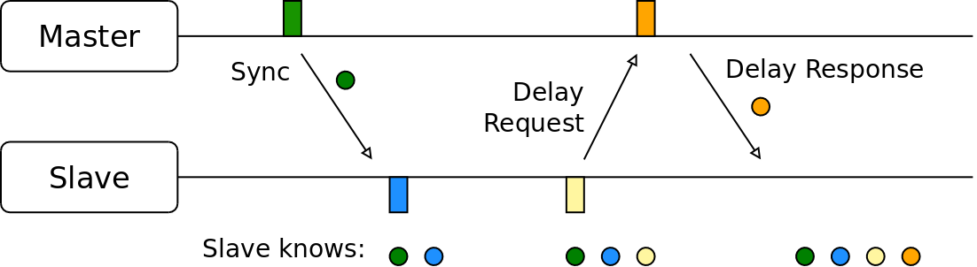
An example for a possible communication between a PTP master and a PTP slave is shown in Figure 1. The master periodically sends information about its current local time to the slave via Sync messages. To estimate the time interval that Sync messages need until they arrive at the slave, the slave has to estimate the path delay. It does so by periodically sending Delay_Requ messages to the master, who then responds with Delay_Resp messages. The colored rectangles in the figure show the points in time when the frames are sent or received. The colored circles below the figure sketch the knowledge on the slave side. Using the collected information the slave is then able to estimate its own offset compared to the master.
III Clock Model
In this section we discuss our approach for having realistic clock noise in our OMNeT++ simulation model.
III-A Problem Statement
The systems we would like to simulate are distributed networks, where each network node has access to a local clock. We are interested in high precision clock synchronization, thus it is important for us that the individual clocks do not provide the exact value of real time, but only a local estimation.
The individual nodes rely on their clocks for two tasks:
-
•
Timestamping: Reading the current value of the local clock to generate a timestamp for a local event.
-
•
Scheduling: Registering an event together with a future timestamp at the local clock. The event will be delivered when the timestamp is reached on the local clock.
OMNeT++ provides Application Programming Interfaces for these two tasks with respect to real-time (simTime() and scheduleAt()). We need to implement similar APIs for the simulation of (noisy) local clocks.
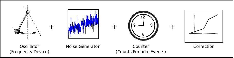
III-B Clock Model
In [6] a model for a digital clock is given. This model consists of an oscillating device and a digital counter, which counts the oscillations. The simulation model for our clocks is based on this model. In a real clock, each of the two components could introduce noise. For our simulation, we are not interested in the exact location inside a clock where the noise is introduced, but only on the effect that can be observed on the outside. Thus, for our own model, we have modified the model from [6] as follows:
-
•
Both the oscillator and the counter are assumed to be absolutely perfect
-
•
In between these two we introduce a new component, called the noise generator. As the name already implies, its sole purpose is to introduce noise in our clock model.
-
•
Finally, we have added a configurable scaling stage after the counter. This component can be used to synchronize the local clock to a reference clock using linear scaling.
A sketch of the complete clock model is given in Figure 2. Subsection III-D describes our implementation of this model.
III-C Clock Noise
Clock devices suffer from various influences that disturb their correct operation. These influences can be categorized as follows [6, 7]:
-
•
Systematic influences (temperature dependence, aging, frequency drift)
-
•
Stochastic noise
The stochastic influences in most frequency sources (including quartz oscillators) can be modeled as a combination of noise processes where the power spectral density is related to the frequency as . This type of noise is referred to as Powerlaw Noise (PLN). For PLN found in common oscillators, it turns out that has integer values in the interval .
While it would be desirable to have all a noise model for our simulations that covers all these effects, I could only implement a subset of them because of timely constraints. Depending on what kind of time intervals are most important for an application, different clock influences have to be considered or can be neglected. As we want to simulate high precision synchronization, I have considered it valuable to have an implementation of PLN, as it provides high-frequency noise as it is common in quartz oscillators. On the other hand, influences like aging can probable neglected without affecting the overall simulation results too much.
III-D Implementation
To reduce the complexity of our implementation, the individual clock tasks are implemented in different classes. Figure 3 shows the relationship between the individual components of our model.
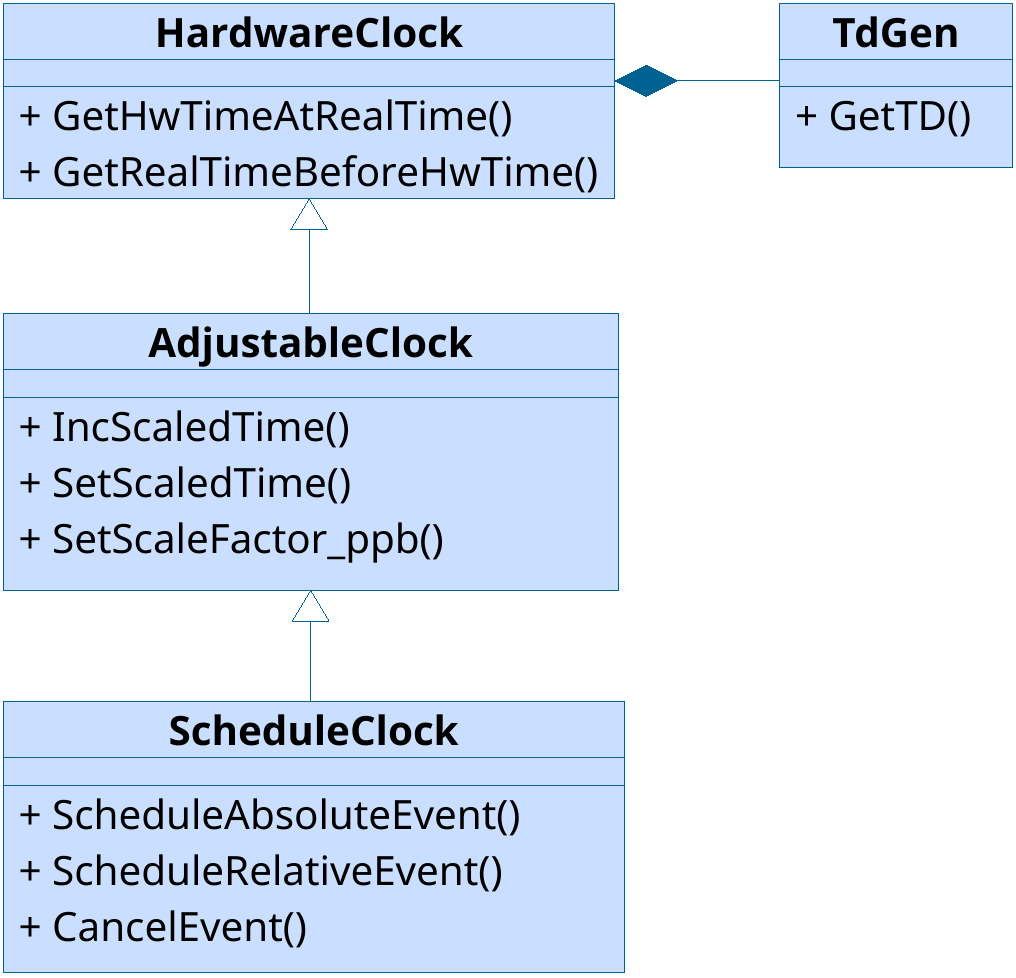
Hardware Clock
The most basic class is the HwClock. Its purpose is the translation between the continuous and perfect real-time, and a discrete imperfect local time estimate. A hardware clock can not be adjusted, and its counter has no relationship to that of other clocks.
To fulfill its task, the hardware clock class relies on a component called TdGen, the Time Deviation (TD) generator. This component implements the current deviation of the local oscillator from the perfect real-time. It is this component that contains the noise model used in the simulation. In my implementation, it uses the above described LibPLN and only simulates Powerlaw Noise. Further s to the noise model could be implemented in this component (e.g. temperature dependence).
The local time estimate for the real-time can then be written as . It is important that we can not assume to have an inverse for this function. But we can rely on the fact that the local time estimation is always increasing. This is important when we want to calculate the real-time when a specified local time estimate will be reached, as we need to this later to implement scheduling.
Adjustable Clock
Adjustable clocks provide an abstraction on top of hardware clocks. Their counter values can be modified, and their progress can be speed up or slowed down. These features enable us to synchronize multiple adjustable clocks to each other.
Schedule Clock
The finale clock class is the ScheduleClock, which provides an interface for other OMNeT++ components to schedule future events. Internally, it stores the scheduled events in an ordered list, and only the first one is actually scheduled. For the scheduling, it relies on the API provided by the hardware clock for real-time estimation together with OMNeT++’s scheduleAt() functionality.
IV PTP Implementation
This section gives a brief overview over LibPTP, our OMNeT++-based implementation of PTP.
IV-A Node Architecture
PTP defines several different types of network nodes (Ordinary Clocks, Boundary Clocks and Transparent Clocks), as well as a large number of configuration options. In LibPTP, all these nodes are derived from a common base class, called PTP_BasicNode. The architecture of this base class is shown in Figure 4. Most components from LibPTP are based on standard models from the INET library333https://inet.omnetpp.org.
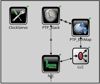
The architecture shown here is a design choice with the intention to represent a basic PTP-capable network device. Any hardware related components have been placed on our simulated Network Interface Card (NIC). Components outside the NIC represent components that would typically be present as software in a real system. The node model here is loosely based on the architecture of a PC with a PTP-capable NIC. This is also why e.g. the clock that is used for the synchronization is shown as part of the simulated NIC.
The layout of our node model is one of the topics where community feedback for the improvement of LibPTP would be greatly appreciated.
PTP Stack
The most important component is the PTP_Stack, which is our implementation of the protocol as it is specified in IEEE 1588-2008 [1].
PTP Ethernet Mapping
PTP does not depend on a single lower layer technology, and various mappings are standardized, e.g for PTP over User Datagram Protocol (UDP), plain Ethernet, or different fieldbus systems. For our project, we focused on PTP over Ethernet, which is specified in Annex F of IEEE 1588-2008. The component PTP_EthMap implements this mapping.
Clock Servo
PTP only specifies a way to estimate the offset of a slave clock in reference to a master clock. How this offset is minimized is the responsibility of the individual implementations, in particular that of the implemented clock servo controller. Our simulation provides a generic interface for clock servos, and an example implementation using a PI-based clock servo design.
LLC
The component labeled LLC in Figure 4 is the Logical Link Control (LLC). It provides access to the NIC based on the EtherType field of Ethernet frames.
NIC
Each PTP node has a NIC with PTP hardware support. Figure 5 shows the internal architecture of our NIC model.
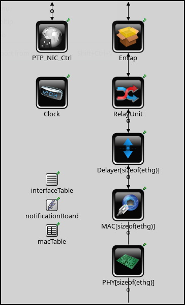
Clock
The clock inside the NIC implements the clock model described in Section III.
Relay Unit
In case a network node with more than one physical network interface is simulated, it is the task of the RelayUnit component to distributed ingressing and egressing frames to the correct ports.
Delay
To simulate arbitrary scheduling/queuing delays, a special Delayer component is added to our simulation model.
MAC
The Media Access Control (MAC) is based on the EtherMAC from INET, but adds timestamping support for PTP frames.
PHY
The physical layer (PHY) model provides support for simulating asymmetric paths.
IV-B Simulations
Using the combination of LibPTP together with LibPLN allows us to carry out simulations of clock synchronization via PTP in OMNeT++.
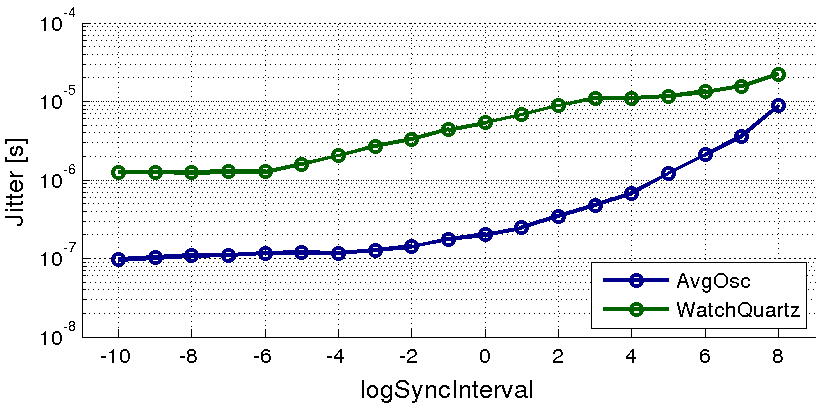
Sync interval
On of the most important parameters for a PTP configuration is the interval for the sending of Sync messages. The synchronization interval in PTP is given via the logSyncInterval parameter as , measured in seconds. Configuring a long interval might degrade the reachable clock synchronization. On the other hand, if an interval is configured which is too short, we might waste network bandwidth without any benefit for the precision of our global time-base. Using OMNeT++’s support for parameter studies, we can configure a PTP network and find out an optimal value empirically.
Suppose we have a simple network, consisting of only two PTP nodes. One of them has an excellent clock, and is the PTP master, while the other has a cheap oscillator and is the PTP slave. Carrying out a parameter study for possible synchronization interval configurations could lead to a graph as shown in Figure 6. The image shows the worst-case jitter of the slave’s time estimate relative to the time of the master.
The slave was simulated to have one of two oscillators: either a cheap quartz oscillator as it could be found in typical consumer electronic devices or a quartz typical for wrist watches. It can be seen that for both types of oscillators, the jitter decreases for shorter intervals, until it reaches an oscillator specific lower bound. Further decreasing the interval won’t lead to better clock synchronization.
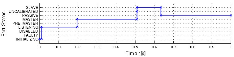
Tracing and debugging
LibPTP provides also sophisticated tracing and debugging support. All relevant PTP properties are available as signals and statistics. As an example, a trace of a PTP port state is shown in Figure 7.
Additionally, it is possible to enable various logging messages. For example, it is easily possible to get a complete trace output of every single decision that is carried out when the nodes execute the BMC or the Data Set Comparision (DSC) algorithms.
V Conclusion
Our project has shown that it is feasible to implement realistic clock noise in OMNeT++, as well as to carry out simulations of clock synchronization via PTP. To best knowledge of the author, it is the most sophisticated implementation of IEEE 1588 in OMNeT++ which is freely available. All source code is released under open source licenses444Most parts are released under the GPL, the rest under the BSD license. on Github555https://github.com/w-wallner/libPTP. Additionally, also a portable library called LibPLN for the efficient simulation of Powerlaw Noise in DES-environment like OMNeT++ was implemented. Again, everything is available to the community as open source on Github666https://github.com/w-wallner/libPTL. The components presented here should help engineers with the difficult task of PTP DSE.
All of the implemented components have been designed to be extensible, so that other users can modify and improve them for their own projects.
VI Future Work
I have worked on this project mainly for my master thesis. During this time, I have worked on it in private. As my thesis is finished now, I have released all related source code under open source licenses, in the hope to find interested community members for further enhancements.
Future improvements to LibPTP could include:
- •
-
•
Mainlining LibPTP: LibPTP is derived from components in the INET library, but it is not related to upstream development. This implies that the projects will drift further apart. It would be of great benefit to try to merge at least some of the work upstream.
-
•
Improving the noise model: Currently, only stochastic noise of oscillators is modeled (using LibPLN). It would be interesting to add support for deterministic influences like temperature to the simulation model. This would allow the simulation to provide even more realistic results.
VII Acknowledgements
I would like to thank my supervisor Armin Wasicek for his support during my master thesis. I am grateful to both the OMNeT++ and INET communities: without the availability of their excellent tools/libraries, my PTP implementation would not have been possible.
- ADEV
- Allan Deviation
- API
- Application Programming Interface
- AVAR
- Allan Variance
- BC
- Boundary Clock
- BMC
- Best Master Clock
- COTS
- Commercial off-the-shelf
- CM
- Compound Module
- CSV
- Comma-separated values
- DSC
- Data Set Comparision
- DES
- Discrete Event Simulation
- DSE
- Design Space Exploration
- E2E
- End-to-End
- FFM
- Flicker Frequency Modulation
- FFD
- Fractional Frequency Deviation
- FIR
- Finite Impulse Response
- FPM
- Flicker Phase Modulation
- FSA
- Frequency Stability Analysis
- FFT
- Fast Fourier transform
- FFTW
- Fastest Fourier Transform in the West
- GPL
- GNU General Public License
- GPS
- Global Positioning System
- GSL
- GNU Scientific Library
- GUI
- Graphical User Interface
- HP
- High Pass
- IDE
- Integrated Development Environment
- IEEE
- Institute of Electrical and Electronics Engineers
- IIR
- Infinite Impulse Response
- ISPCS
- International IEEE Symposium on Precision Clock Synchronization for Measurement, Control and Communication
- LAN
- Local Area Network
- LLC
- Logical Link Control
- MAC
- Media Access Control
- MAVAR
- Modified Allan Variance
- NED
- Network Description
- NIC
- Network Interface Card
- NTP
- Network Time Protocol
- OC
- Ordinary Clock
- OCXO
- Oven Controlled Crystal Oscillator
- OMNeT++
- Objective Modular Network Testbed in C++
- OS
- Operating System
- P2P
- Peer-to-Peer
- PC
- Personal computer
- PHY
- physical layer
- PI
- proportional-integral
- PID
- proportional-integral-derivative
- PLN
- Powerlaw Noise
- PSD
- Power Spectral Density
- PTP
- Precision Time Protocol
- RGMII
- Reduced Gigabit Media-Independent Interface
- RTS
- Real-Time System
- RW
- Random Walk
- SP
- Scale Point
- SM
- Simple Module
- TC
- Transparent Clock
- TD
- Time Deviation
- TDG
- TD Generator
- TDO
- TD Oracle
- TDV
- TD Vector
- TDVG
- Vector (TDV) Generator
- TDVS
- TDV Storage
- TDEC
- Estimator (TDE) Chain
- TDE
- TD Estimator
- TSA
- Time Series Analysis
- UML
- Unified Modeling Language
- UDP
- User Datagram Protocol
- WFM
- White Frequency Modulation
- WPM
- White Phase Modulation
References
- [1] IEEE Standard for a Precision Clock Synchronization Protocol for Networked Measurement and Control Systems IEEE Std. 1588-2008, 2008.
- [2] W. Wallner, Simulation of Time-synchronized Networks using IEEE 1588-2008 Master’s thesis, Faculty of Informatics, Vienna University of Technology, 2016.
- [3] G. Gaderer et al, Achieving a Realistic Notion of Time in Discrete Event Simulation International Journal of Distributed Sensor Networks, 2011.
- [4] N. Kasdin and T. Walter, Discrete Simulation of Power Law noise Proceedings of the 1992 IEEE Frequency Control Symposium, 1992.
- [5] J. C. Eidson, Measurement, Control, and Communication Using IEEE 1588 Springer, 2006.
- [6] D. W. Allan, N. Ashby, C. C. Hodge, Application Note 1289: The Science of Timekeeping Agilent Technologies, 2000.
- [7] W. J. Riley, NIST Special Publication 1065: Handbook of Frequency Stability Analysis National Institute of Standards and Technology, U.S. Department of Commerce, 2008.