A Portable, 3D-Printing Enabled Multi-Vehicle Platform for Robotics Research and Education
Abstract
microMVP is an affordable, portable, and open source micro-scale mobile robot platform designed for robotics research and education. As a complete and unique multi-vehicle platform enabled by 3D printing and the maker culture, microMVP can be easily reproduced and requires little maintenance: a set of six micro vehicles, each measuring cubic centimeters and weighing under grams, and the accompanying tracking platform can be fully assembled in under two hours, all from readily available components. In this paper, we describe microMVP's hardware and software architecture, and the design thoughts that go into the making of the platform. The capabilities of microMVP APIs are then demonstrated with several single- and multi-robot path and motion planning algorithms. microMVP supports all common operation systems.
I Introduction
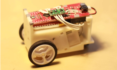
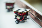
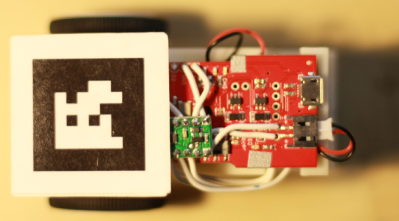
In this paper, we introduce an affordable, portable, and open source multi-vehicle hardware and software platform, microMVP 111We call the overall system as microMVP, standing for micro-scale Multi-Vehicle Platform. (Fig. 1 (a)), for research and education efforts requiring single or multiple mobile robots. microMVP consists of highly compact micro-vehicles, a state tracking camera system, and a supporting software stack. Each micro-vehicle (Fig. 1 (b)) has a rigid 3D-printed shell allowing the precise (snap-on) fitting of the essential components–the Arduino-based sensorless vehicle measures less than -cm in length and can be controlled wirelessly at a frequency of over Hz. The external state-tracking system consists of a single USB webcam for estimating the configurations of the vehicles (in ). The overall system is capable of feedback control of the entire vehicle fleet at a control update frequency of Hz and above. The components in each vehicle costs less than 90 USD and the tracking platform costs about 80 USD. We expect the cost of microMVP to drop significantly with the release of future iterations of the platform.
(a)
(b)
We develop microMVP with both research and education applications in mind. The relatively high accuracy of microMVP with respect to its state estimation and control capabilities renders the platform suitable as a testbed for single- or multi-robot path and motion planning algorithms. As examples, we demonstrate that microMVP can seamlessly integrate (i) centralized multi-robot path planning algorithms [1] and (ii) (distributed) reciprocal velocity obstacle algorithms [2, 3]. On the educational side, the affordability and portability of microMVP makes it ideal for the teaching and self-education of robotics subjects involving mobile robots. Moreover, the platform requires little time commitment to reproduce and maintain. The tracking platform requires minimal setup and each vehicle can be built in under 20 minutes.
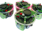
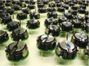
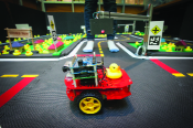
Related work and differentiation. Since a large number of mobile robots have been produced with various capabilities and we cannot hope to enumerate them all, here, we focus on recent research- and education-centered ground mobile robot platforms intended for multi-robot coordination and collaboration tasks. Due in part to the rapid advances in MEMS technology in recent years and the related maker movement222https://en.wikipedia.org/wiki/Maker_culture, it becomes increasingly feasible for robotics researchers, educators, and hobbyists alike to produce highly capable mobile robots at lower costs. Representative ones include the e-pucks educational robots [4], kilobots collective mobile robots [5], the duckiebot autonomous mobile robots333http://duckietown.mit.edu/, and Robotarium [6]. The e-puck robots [4] are differentially driven robots (DDR) with two independent motor thrust input. An e-puck robot measures in diameter and weighs about grams. It hosts an array of sensors including microphone arrays, proximity sensors, accelerometers, and so on. Kilobots [5] are smaller coin sized robots that locomote via vibration (over smooth surfaces), making them ideal for experimenting with collective behavior that is frequently found in nature [7]. The duckiebots present a recent attempt from MIT for teaching students about autonomous driving with hands on experience. Robotarium is a recent NSF funded effort at GeorgiaTech that is intended as a remotely accessible, extensive robotics testbed, which includes a multi-vehicle platform with inch-sized DDR vehicles.
 |
 |
|
| (a) | (b) |
 |
 |
|
| (c) | (d) |
Each of the above-mentioned mobile robot platforms has its particular strengths. However, when it comes to robot path planning, these platforms also have their limitations. For example, e-pucks are compact and capable, but they are expensive to acquire and maintain, costing 1K+ USD each. kilobots, great for swarm-related studies, are not ``garden variety'' mobile robots, making them unsuitable for multi-robot path planning experiments. Platforms like Duckiebots and Robotarium's also have their drawbacks (e.g., larger footprint and remote accessibility, respectively). To address our own research and education needs, and seeing the limitations of existing solutions for the general task of single- and multi-robot path planning, we developed microMVP for filling the gap as a capable, affordable, portable, readily available, and low maintenance multi-vehicle platform.
Contributions. microMVP is a capable, simple, affordable mobile robot platform with a very small footprint. First and most importantly, as we will demonstrate, microMVP is highly capable as an experimental platform for both centralized and distributed multi-robot planning and coordination tasks. Secondly, it presents a solution that is fairly portable and compact, suitable for showcasing multi-robot systems in action in limited space, making it ideal for both research and education. Last but not least, microMVP's open source design, utilizing 3D printing technology, is extremely simple and robust. Significant care is also taken to ensure that only readily available components are used, which makes microMVP a truly readily reproducible mobile robot platform.
The rest of the paper are organized as follows. In Section II, we describe the hardware architecture of microMVP, followed by a summary of thoughts going into the design of the software stack in Section III. We highlight the applications and capabilities of microMVP in Section IV and conclude in Section V. We note that this paper describes mainly microMVP's design philosophy and capabilities. Additional details of the system, including component acquisition, assembly instructions, API interfaces, examples, can be found at http://arc.cs.rutgers.edu/mvp/.
II Platform Architecture and Design
The main goal in designing microMVP is to optimally combine portability and availability. Availability further entails affordability, component availability, and low system assembly and maintenance time. To reach the design target, we explored a large number of micro controller families (Arduino, mbed, and Raspberry Pi), wireless technology (wifi, zigBee, and Bluetooth), motors and motor controllers, overall vehicle design (3D printing, laser cut machining, and off-the-shelf kits), and tracking technology (infrared-marker, fiducial marker). We eventually fixated on the design choice of using Arduino/zigBee for communication and control, plastic gear motors for mobility, and fiducial markers for system tracking.
microMVP has two main components: (i) a 3D-printing enabled micro-vehicle fleet and (ii) a fiducial marker tracking system for vehicle state estimation. Fig. 1 illustrates the platform architecture (with vehicles, additional vehicles can be readily added without additional infrastructure) and provides a picture of a single fully assembled vehicle. The general architecture of microMVP is rather straightforward: the web-cam based sensing system continuously queries the configuration of the vehicles, upon which planning decisions are made and translated into control signals that are relayed wirelessly to the vehicles. microMVP can run the feedback control loop at a frequency of up to Hz, or as high as limited by the frames-per-second (fps) rating of the camera's capture mode. For webcams, this is normally fps or fps. In what follows, we describe the design of the individual components of microMVP in more detail.
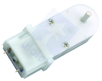
II-A 3D-Printing Enabled Micro-Scale Vehicles
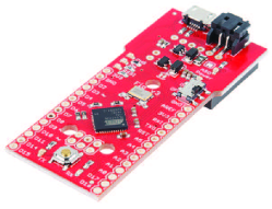
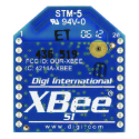
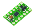
We design the vehicle to be small, affordable, reliable, and easily reproducible. To reach the design goal of reliability while maintaining simplicity, the vehicle is built around the proven zigBee Series 1 (Fig. 3(b)) as the wireless communication module (zigBees are frequently found in research drones). For actuation, two micro gear motors (Fig. 3(d)) are connected to Pololu DRV8835 dual motor driver carrier (Fig. 3(c)). Then, the zigBee module, the motor driver carrier, and a 400mAh 3.7v Li-ion battery are fitted to a Sparkfun fio v3 board (Fig. 3(a)) which is Arduino compatible. In additional to built-in zigBee support, the fio v3 board allows direct charging of the battery, a convenient feature. To put things together, all components are snapped into a 3D printed plastic shell and wheels are attached to the motors. The use of 3D printing is essential in the design phase, allowing both the precise fitting of the components and a quick screw-less assembly. Finally, a small caster wheel is attached to reduce the friction of the vehicle, completing the vehicle hardware (Fig. 1(b)), which measures less than and weighs just below 100 grams. A fully charged battery allows the vehicle to operate continuously for about one and half hours. Recharging on a standard 0.5A USB port takes less than one hour.
 |
 |
|
| (a) | (b) |
 |
 |
|
| (c) | (d) |
The components of the vehicle cost less than 90 USD in total (please refer to the project website for a list of individual components and their costs). Excluding the time required for 3D printing of the vehicle shell, it takes less than 20 minutes to assemble the vehicle. All that is required is to solder a number of wires, glue together a few components, and snap them together. We tested the vehicles over a variety of flat surfaces commonly found in classrooms, offices and labs, including wood floors, thin carpets, vinyl floors, and concrete slabs. We could verify that the vehicles do not need special surfaces to operate. The top speed of the vehicles is relatively uniform on different surfaces with the exception of carpeted surface, where the top speed is reduced as the thickness of the carpet increases.
II-B Camera Platform for Vehicle Tracking
microMVP uses a single USB camera (we selected the Logitech C920, max resolution) for tracking the configurations of the vehicles. The camera is mounted to a microphone stand with a tripod base and adjustable height. The cost-effective setup, with the camera mounted at a height about and facing down, establishes an approximately rectangular workspace for the vehicles at the ground level. The camera platform can comfortably accommodate to vehicles depending on the application. For vehicle tracking, after evaluating several open source fiducial marker based tracking package, we opted for chilitags444https://github.com/chili-epfl/chilitags as the baseline platform for tracking vehicle states. This requires the fixture of markers on the vehicles, for which we used a marker size of (without the extra white borders; some borders must be included for good tracking quality).
II-C Computation Hardware
As illustrated in Fig. 1, microMVP system requires two pieces of enabling computation: tracking and control. We note that Fig. 1 includes two computers to suggest that the system is rather modular, i.e., the tracking and the control are easily separated. The computation, however, can be carried out using a single multi-core commodity PC.
III Software Stack and API
Our design on the software side of microMVP seeks to maximize modularity, simplicity, and cross-platform compatibility. Modularity enables flexibility in hardware setup and more importantly, extends the capability of the system. Simplicity and cross-platform compatibility are essential for any system aimed at mass adoption, especially for educational purposes. Below, we briefly describe how microMVP achieves these design goals in its software stack and application programming interface (API) implementation. For cross-platform and rapid development support, we chose Python as the language for developing the API, which has a state estimation component and a vehicle control component.
III-A Vehicle State Estimation
For state estimation, to extract the configurations of the vehicles in (i.e., ), we attach a chilitags fiducial marker on the top of the micro vehicles so that the front side of the tag is aligned with the front of the vehicle and the center of tag overlaps the mid point between the two motor axles (see Fig. 4).
The chilitags library provides open source APIs for extracting tags locations from images. The reported tag location (e.g., the coordinates of the four corners of a tag within a raster image), combined with known physical size of the tag and known camera orientation/calibration, allows the estimation of the position and orientation of the tags. As vehicles in microMVP live on the floor, there is no need to extract the configurations of the tags; is sufficient. For continuous image acquisition through the USB camera, one may use OpenCV (Open Source Computer Vision Library) [8]. With a calibrated camera and the right parameters (e.g., exposure, white balance, and so on), we are able to track 50 tags simultaneously at 30 frames per second and rarely miss any of the tags. It appears that the limiting factor with respect to the frame rate of the system mainly hinges on the frame rate of the USB camera.
To allow user of microMVP access to the tags' 2D configurations, we adapt a queuing architecture much like ``topics'' in the Robotic Operation System (ROS). More specifically, we use a publisher-subscriber model from ZeroMQ 555http://zeromq.org/ to deliver vehicle position data over the network. An end user may asynchronously request in Python, in a thread-safe manner, the latest vehicle positions in either for all vehicles or for a subset of vehicles.
III-B Vehicle Control
Suppose that an end user has made control decisions for each vehicle in a vehicle swarm, in the form of thrusts for the wheels. microMVP provides a Python interface that allows the direct delivery of such control input to the desired vehicle. To realize this, a simple data transfer protocol is developed to operate over an automated zigBee link between the control computer and the individual vehicles. The zigBee modules all operate in the same mode and form a communication graph that is a complete graph, although the effective communication graph is a directed star graph because vehicles only receive data from the control computer and do not send any data. On the vehicle side, the Arduino-based Fio v3 board continuously monitor the zigBee serial interface for new input. We found that the zigBee interface can sometimes become unreliable, a behavior that must be compensated through software. Through a careful implementation, we were able to reliably deliver motor thrusts to 14 vehicles at a frequency of 50Hz. A feedback loop running at 10Hz is generally sufficient for controlling these micro vehicles.
In addition to basic control APIs that allow sending motor thrusts to the vehicles, microMVP also supplies many high level APIs that relieve the user from tedious tasks such as synchronous path following (see Section IV).
III-C Additional Features and Extensions
microMVP comes with many additional features and extensions. We mention a few such possibilities here.
Multi-platform support. In the development of microMVP, we made a conscious effort to build a software stack that is inherently multi-platform friendly. In addition to selecting Python as the language for development, the libraries that we use all have cross-platform support.
Vehicle simulation. The vehicle that we developed is inherently a icra-2017 ly driven robot, the configuration transition equation of which may be represented as [9]
| (1) |
in which is the wheel radius, and are the control input to the right and left wheels, respectively, and is the distance between the two wheels' centers. is the configuration of the vehicle.
It is relatively straightforward to simulate other vehicle motion models with DDR. As an example, looking at Dubin's Car [9], e.g.,
| (2) |
in which and are some constant line and angular velocity, respectively, we observe that (1) may readily simulate (2). Similarly, other vehicle types including Reeds-Shepp car, simple car, unicycle, can all be simulated using a DDR vehicle.
Enhanced portability. The entire microMVP platform can be put in a small box minus the camera stand. It is possible to run both vehicle tracking and vehicle control on the same computer, suggesting that the entire system is highly portable. Alternatively, one may choose to offload the vehicle tracking computation to a dedicated system with minimal footprint. As a proof of concept, we have tested running the system on a Raspberry Pi 2 model B and confirm it has full functionality.
ROS integration. microMVP, given that its source is open, can be readily adapted to work with ROS. In particular, the ZeroMQ based message queuing can be replaced with ROS topics. Similarly, vehicle control can also be packaged into a topic-based launch module. Due to the relatively large footprint of ROS installation and our design goals, microMVP is made independent of ROS.
IV Capabilities and Applications of microMVP
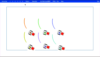
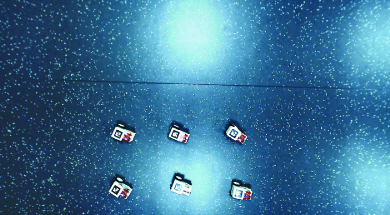
After describing the hardware and software structures of microMVP, we provide several application scenarios demonstrating the capability of microMVP. We note that some of these capabilities, for example path following, are also part of microMVP APIs that an end user may readily use. A Python-based control graphical user interface (GUI) (see Fig. 5 for a snapshot of the GUI and the the corresponding hardware experiment in action) tracks and displays the locations of the vehicles in real-time.
(a)
(b)
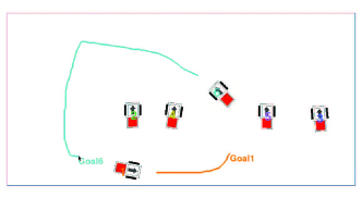
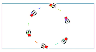
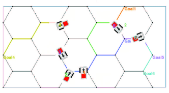
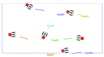
We highlight four application scenarios: (i) arbitrary path following for an ``active'' vehicle, (ii) synchronized path following, (iii) running distance optimal multi-robot path planning algorithms over a hexagonal grid, and (iv) distributed path planning using reciprocal velocity obstacles. GUI snapshots of these scenarios are provided in Fig. 6. All these scenarios are included in the accompanying video, also available at https://youtu.be/gXayWyRWDsw. We intentionally shot the video as a real-time long take with no editing to demonstrate the reliability and robustness of microMVP when transitioning between different scenarios.
 |
(a) | |
 |
(b) | |
 |
(c) | |
 |
(d) |
IV-A Path Following
microMVP has built-in support for waypoint-based path tracking and following. At the single vehicle level, we adopt the pure pursuit [10, 11] algorithm that computes the desired curvature for a given look-ahead distance (see Fig. 7). The curvature then translates to desired motor thrusts, allowing the vehicle to follow the input path (Fig. 6(a)).
In a multi-vehicle setup, several issues must be considered in microMVP: (i) the low-priced motors are inherently inaccurate in mapping input motor thrusts to output rotational speeds, (ii) uneven drag on the ground, (iii) camera lens induced workspace distortion, (iv) path curvature induced linear speed mismatch, and (v) motor speed variation due to battery drain variations. In computing motor thrusts for achieving desired curvature, microMVP limits the maximum thrust for each wheel motor at roughly of the maximum possible. This design choice leaves flexibility when it comes to synchronizing the movements of multiple vehicles. Roughly speaking, using waypoints with attached timestamps, microMVP dynamically adjust the maximum allowed motor thrusts, speeding up vehicles that fall behind and slowing down the ones that are ahead. With this mechanism, microMVP allows vehicles to accurately perform synchronized ``dance moves'' (Fig. 6(b)).
IV-B Optimal Multi-Robot Path Planning
To further verify the synchronous path following capability of microMVP, we integrated the optimal graph-based multi-robot path planning algorithm [1] into microMVP. Specifically, we tested the algorithm MinMaxDist that minimizes the maximum distance traveled by any vehicle over a hexagonal grid. The size of the grid is determined using the vehicle footprint (see [12]). For randomly generated goals for the fully distinguishable vehicles, we employ MinMaxDist to compute the paths, turn them into waypoint-based, time-synchronized trajectories, and then invoke the pure pursuit based path following API of microMVP to track these trajectories (Fig. 6(c)).
IV-C Reciprocal Velocity Obstacles
microMVP also supports the distributed reciprocal velocity obstacle (RVO) based path planning algorithms. With minimal effort, we were able to integrate microMVP with the RVO2 library [2, 3]. Because RVO produces velocity profiles, we derive current vehicle velocities from vehicle locations. Then, the desired output velocities are simulated for a few steps to generate a set of paths with time synchronized waypoints. We may then invoke path following capability of microMVP to track these paths repeatedly (Fig. 6(d)).
V Conclusion and Future Work
In this paper, we summarized the design, implementation, and capabilities of microMVP. microMVP is intended to serve as a testbed for multi-robot planning and coordination algorithms and as an educational tool in the teaching of robotics subjects including mobile robots and multi-robot systems. Enabled by 3D-printing and the maker culture, microMVP is highly portable, readily affordable, low maintenance, and yet highly capable as an open source multi-vehicle platform.
microMVP will be continuously improved in its current and future iterations. On the hardware side, with the rapid development of IC technologies and improved design, the vehicles will become smaller, more accurate, and at the same time more affordable. In particular, we expect the release of a smaller vehicle costing around 35 USD in in the near future. We will also add on-board sensing capabilities to the vehicles while maintaining the platform's affordability. On the software side, to improve the accuracy of vehicle state estimation, we are working on a Extended Kalman Filter (EKF) to improve the sensing accuracy. Additional vehicle control APIs, including high level path planning with obstacle avoidance, will also be added to microMVP. Last, this open source effort hopes to solicit designs from all interested parties to make microMVP a community-based effort to promote robotics research and education.
References
- [1] J. Yu and S. M. LaValle, ``Optimal multi-robot path planning on graphs: Complete algorithms and effective heuristics,'' IEEE Transactions on Robotics, to appear.
- [2] J. van den Berg, M. C. Lin, and D. Manocha, ``Reciprocal velocity obstacles for real-time multi-agent navigation,'' in Proceedings IEEE International Conference on Robotics & Automation, 2008, pp. 1928–1935.
- [3] J. Snape, S. J. Guy, J. van den Berg, and D. Manocha, ``Smooth coordination and navigation for multiple differential-drive robots,'' in Experimental Robotics. Springer, 2014.
- [4] F. Mondada, M. Bonani, X. Raemy, J. Pugh, C. Cianci, A. Klaptocz, S. Magnenat, J.-C. Zufferey, D. Floreano, and A. Martinoli, ``The e-puck, a robot designed for education in engineering,'' in Proceedings of the 9th conference on autonomous robot systems and competitions, vol. 1, no. LIS-CONF-2009-004. IPCB: Instituto Politécnico de Castelo Branco, 2009, pp. 59–65.
- [5] M. Rubenstein, C. Ahler, N. Hoff, A. Cabrera, and R. Nagpal, ``Kilobot: A low cost robot with scalable operations designed for collective behaviors,'' Robotics and Autonomous Systems, vol. 62, no. 7, pp. 966–975, 2014.
- [6] D. Pickem, L. Wang, P. Glotfelter, Y. Diaz-Mercado, M. Mote, A. Ames, E. Feron, and M. Egerstedt, ``Safe, remote-access swarm robotics research on the robotarium,'' arXiv preprint arXiv:1604.00640, 2016.
- [7] C. W. Reynolds, ``Flocks, herds, and schools: A distributed behavioral model,'' Computer Graphics (ACM SIGGRAPH 87 Conf. Proc.), vol. 21, pp. 25–34, 1987.
- [8] Itseez, ``Open source computer vision library,'' https://github.com/itseez/opencv, 2015.
- [9] S. M. LaValle, Planning Algorithms. Cambridge, U.K.: Cambridge University Press, 2006, also available at http://planning.cs.uiuc.edu/.
- [10] R. Wallace, A. Stentz, C. E. Thorpe, H. Maravec, W. Whittaker, and T. Kanade, ``First results in robot road-following.'' in IJCAI, 1985, pp. 1089–1095.
- [11] R. C. Coulter, ``Implementation of the pure pursuit path tracking algorithm,'' DTIC Document, Tech. Rep., 1992.
- [12] J. Yu and D. Rus, ``An effective algorithmic framework for near optimal multi-robot path planning,'' in Proceedings International Symposium on Robotics Research, 2015.