∎
LIMSI, CNRS, Université Paris-Saclay, F-91405 Orsay, France
22email: xu@fast.u-psud.fr 33institutetext: Damir Juric 44institutetext: Jalel Chergui55institutetext: LIMSI, CNRS, Université Paris-Saclay, F-91405 Orsay, France
Damir Juric
55email: damir.juric@limsi.fr
Jalel Chergui
55email: jalel.chergui@limsi.fr 66institutetext: Seungwon Shin 77institutetext: Department of Mechanical and System Design Engineering, Hongik University, Seoul 121-791, Republic of Korea
Three dimensional simulations of viscous folding in diverging microchannels
Abstract
Three dimensional simulations on the viscous folding in diverging microchannels reported by Cubaud and Mason (2006a) are performed using the parallel code BLUE for multi-phase flows (Shin et al, 2014). The more viscous liquid is injected into the channel from the center inlet, and the less viscous liquid from two side inlets. Liquid takes the form of a thin filament due to hydrodynamic focusing in the long channel that leads to the diverging region. The thread then becomes unstable to a folding instability, due to the longitudinal compressive stress applied to it by the diverging flow of liquid . Given the long computation time, we were limited to a parameter study comprising five simulations in which the flow rate ratio, the viscosity ratio, the Reynolds number, and the shape of the channel were varied relative to a reference model. In our simulations, the cross section of the thread produced by focusing is elliptical rather than circular. The initial folding axis can be either parallel or perpendicular to the narrow dimension of the chamber. In the former case, the folding slowly transforms via twisting to perpendicular folding , or it may remain parallel. The direction of folding onset is determined by the velocity profile and the elliptical shape of the thread cross section in the channel that feeds the diverging part of the cell. Due to the high viscosity contrast and very low Reynolds numbers, direct numerical simulations of this two-phase flow are very challenging and to our knowledge these are the first three-dimensional direct parallel numerical simulations of viscous threads in microchannels. Our simulations provide good qualitative comparison of the early time onset of the folding instability however since the computational time for these simulations is quite long, especially for such viscous threads, long-time comparisons with experiments for quantities such as folding amplitude and frequency are limited.
Keywords:
Three dimensional viscous folding diverging microchannel1 Introduction
The folding of viscous threads in diverging microchannels has recently attracted much attention due to the need to mix two fluids with very different viscosities. The dynamics of viscous multiphase flows at small scales is important in industrial technology (oil recovery, biodiesel production, etc.). Microfluidic devices are well suited for studying precisely controlled flow geometries and finely manipulating the fluid, and can be used to produce individual bubbles, droplets and complex soft materials (Utada et al, 2005; Cubaud et al, 2005; Meleson et al, 2004). The effective mixing is of great importance in these various microfluidic applications. But microfluidic flows are usually laminar, so liquid streams are parallel and different fluids can only mix by diffusion. The time scale associated with diffusion, , where is the characteristic length scale and is the diffusion coefficient between the liquids, is typically much larger than the time scale associated with convection, , where is the characteristic flow velocity. Therefore, diffusion alone is an extremely inefficient mixing method.
There are different innovative strategies to enhance mixing in microfluidics, which can be classified as either active or passive methods. In active methods an external forcing is imposed by e.g. rotary pumps (Chou et al, 2001), forced oscillatory transverse flows (Bottausci et al, 2004) or electric or magnetic fields (Paik et al, 2003a, b; Pollack et al, 2002; Kang et al, 2007a, b; Rida and Gijs, 2004). Passive methods rely on a particular design of the microchannel, including patterned surface relief (Chen et al, 2009; Bringer et al, 2004; Stroock et al, 2002a, b). However, industrial and biological fluids usually exhibit widely different viscosities and the relative motions between the fluids are complex. In this article we study one promising method, wherein periodic folding of viscous threads injected into microchannels enhances mixing by greatly increasing the specific surface area of the fluid/fluid interface.
The buckling (folding or coiling) of slender viscous threads is familiar to anyone who has ever poured honey or molten chocolate onto toast. Taylor (1969) investigated the viscous buckling problem and suggested that the instability requires an axial compressive stress, like the more familiar ‘Euler’ buckling of a compressed elastic rod. Since then, viscous buckling has been studied by numerous authors using experimental, theoretical, and numerical approaches (Cruickshank and Munson, 1982b, a, 1983; Cruickshank, 1988; Griffiths and Turner, 1988; Tchavdarov et al, 1993; Mahadevan et al, 1998; Skorobogatiy and Mahadevan, 2000; Tome and Mckee, 1999; Ribe, 2004; Ribe et al, 2006; Maleki et al, 2004; Habibi et al, 2014). The primary result of this work is that buckling can occur in four distinct modes (viscous, gravitational, inertio-gravitational, and inertial) depending on the force that balances the viscous resistance to bending as a function of fall height.
With the exception of Griffiths and Turner (1988), all the studies cited above consider ‘non-immersed’ folding/coiling that occurs when the influence of the external fluid (typically air in experiments) is negligible. Recently, Cubaud and Mason (2006a) have studied the immersed buckling that occurs when two fluids with different viscosities are injected into a diverging microchannel. The thread is produced by hydrodynamic focusing of a viscous fluid flow by a less viscous fluid injected from the sides. Silicone oils with different viscosities were used to obtain different viscosity ratios. On the basis of their experimental results, Cubaud and Mason (2006a) proposed that , where is the folding frequency and is the characteristic shear rate. The thread of radius can be assumed to flow at nearly constant velocity, , like a solid plug, inside a sheath of the less viscous liquid, similar to the flow in a circular channel. In this case, represents the maximum velocity of the surrounding liquid. Downstream, the thread and surrounding liquid enter the diverging channel creating a decelerating extensional flow. Extensional viscous stresses cause the thread to bend and fold, rather than dilate, in order to minimize dissipation and conserve mass. As the thread folds, it reduces its velocity and mixes with the outer liquid. In addition to folding, many other potentially useful flow phenomena are obtained, including oscillatory folding, folding modified by strong diffusion, heterogeneous folding, and subfolding (Cubaud and Mason, 2006b).
Chung et al (2010) performed numerical and experimental studies on viscous folding in diverging microchannels similar to those of Cubaud and Mason (2006a). However, it is important to note that the numerical simulations of Chung et al (2010) are two-dimensional, unlike their or Cubaud’s experiments which are fully three-dimensional. Chung et al (2010) obtained a regime diagram for the flow pattern observed (stable, folding, or chaotic) as a function of the flow rate ratio, the viscosity ratio, and the channel shape. In addition to the divergence angles and , Chung et al (2010) also performed simulations for a channel with walls of hyperbolic shape, to obtain a more uniform compressive stress along the channel’s centerline. The hyperbolic channel generated folding flows with smaller frequency and amplitude, as well as a delay of onset of the folding. There are two main differences between Chung’s simulations and Cubaud’s experiments. First, Chung et al (2010) found the existence of an upper bound of viscosity ratio for folding instability. Secondly, Chung et al (2010) obtained a power-law relation , which is quite different from the Cubaud and Mason (2006a) law .
For fluids with a large viscosity ratio, the thread generated by hydrodynamic focusing requires a long focusing channel to become thin. The existence of an upper bound of viscosity ratio for the folding instability could be owed to the thick thread, because the focusing channel is short in the study of Chung et al (2010). Three-dimensional simulations promise to be helpful in understanding such details of the viscous folding phenomenon. To this end, we use the parallel code BLUE for multiphase flow based on the front tracking method (developed by Shin, Chergui, and Juric (2014)) to simulate three-dimensional viscous folding in diverging microchannels. The computational domain includes a focusing channel sufficiently long to allow the full formation of threads as in the experiments of Cubaud and Mason (2006a).
2 Methods
2.1 Mathematical formulation
Here we describe the basic solution procedure for the Navier-Stokes equations with a brief explanation of the interface method. The governing equations for an incompressible two-phase flow can be expressed by a single field formulation as follows:
| (1) | ||||
| (2) |
where is the velocity, is the pressure, is the gravitational acceleration, and is the local surface tension force at the interface.
The fluid properties such density or viscosity are defined in the entire computational domain:
| (3) | ||||
| (4) |
Where the subscripts 1 and 2 stand for the respective phases. The indicator function , a numerical Heaviside function, is zero in one phase and unity in the other phase. Numerically, is resolved with a sharp but smooth transition across 3 to 4 grid cells and is generated using a vector distance function computed directly from the tracked interface (Shin and Juric, 2009a, b).
The surface tension can be described by the hybrid formulation
| (5) |
where is the surface tension coefficient, is twice the mean interface curvature field calculated on the Eulerian grid using
| (6) | ||||
| (7) | ||||
| (8) |
Here is a parameterization of the interface , and is a Dirac distribution that is non-zero only when . is the unit normal vector to the interface and is the length of the interface element. is again twice the mean interface curvature, but obtained from the Lagrangian interface structure. The geometric information, unit normal and length of the interface element in , are computed directly from the Lagrangian interface and then distributed onto an Eulerian grid using the discrete delta function. The details following Peskin’s (Peskin, 1977) well known immersed boundary approach and a description of our procedure for calculating the force and constructing the function field can be found in Shin and Juric (2007).
The Lagrangian elements of the interface are advected by integrating
| (9) |
with a second order Runge-Kutta method where the interface velocity is interpolated from the Eulerian velocity.
2.2 Numerical method
The treatment of the free surface uses the Level Contour Reconstruction Method (LCRM), a hybrid Front Tracking/Level Set technique. The LCRM retains the usual features of classic Front Tracking: to represent the interface with a triangular surface element mesh, to calculate the surface tension and advect it. A major advantage of the LCRM, compared with standard Front Tracking, is that all the interfacial elements are implicitly instead of logically connected. The LCRM periodically reconstructs the interface elements using a distance function field, such as the one in the Level Set method, thus allowing an automatic treatment of interface element restructuring and topology changes without the need for logical connectivity between interface elements.
The Navier-Stokes solver computes the primary variables of velocity and pressure on a fixed and uniform Eulerian mesh by means of Chorin’s projection method (Chorin, 1968) with implicit solution of velocity. For the spatial discretization we use the well-known staggered mesh, MAC method (Harlow et al, 1965). The pressure and the distance function are located at cell centers while the components of velocity are located at cell faces. All spatial derivatives are approximated by standard second-order centered differences.
The code structure consists essentially of two main modules: (1) a module for solution of the incompressible Navier-Stokes equations and (2) a module for the interface solution including tracking the phase front, initialization and reconstruction of the interface when necessary. The parallelization of the code is based on algebraic domain decomposition, where the velocity field is solved by a parallel generalized minimum residual (GMRES) method for the implicit viscous terms and the pressure by a parallel multigrid method motivated by the algorithm of Kwak and Lee (2003). Communication across process threads is handled by message passing interface (MPI) procedures.
Further detailed informations can be found in Shin et al (2014).
2.3 Problem definition

Fig. 1 shows the computational domain, which is similar to that used by Cubaud and Mason (Cubaud and Mason, 2006a). The geometry is composed of two subdomains: the flow-focusing part and the flow-diverging part. The more viscous liquid with viscosity is injected into the channel from the center inlet at a volumetric rate , and the less viscous liquid with viscosity from two side inlets at a total volumetric rate . The interfacial tension between two liquids is .The dimensions of the simulation domain are mm mm mm. The width of the inlets and the microchannel is mm and the length of the long focusing channel is mm. We use a Neumann boundary condition on the outlet, where the velocity derivatives are set to .
Some important dimensionless numbers are defined as follows:
| (10) | ||||
| (11) | ||||
| (12) | ||||
| (13) | ||||
| (14) | ||||
| (15) |
The characteristic length scale , and the characteristic velocities in Reynolds numbers and are the average velocities and can be calculated from the volume flow flux and geometry parameters and . The capillary numbers are calculated in the long focusing channel, the characteristic velocity is . Furthermore, we designed different channel geometries with two different diverging angles and for the main chamber.
A reference simulation (case 1) is chosen and its detailed parameters and dimensionless numbers are shown in Table 1.
| Variables | Units | Values |
|---|---|---|
| kg/mm3 | ||
| kg/mm/s | ||
| kg/mm/s | ||
| mm3/s | 0.83333 | |
| mm3/s | 10 | |
| kg/s2 | ||
| 3.57 | ||
| 330.64 | ||
| 0.15 | ||
| 1/12 | ||
| 2174 | ||
In our parameter study, five simulations are performed. The dimensionless quantities for these cases are given in Table 2. In all 5 simulations the capillary number is kept constant at , the surface tension force is small compared to the viscous force for the liquid . All the simulations are implemented using 64 () computational cores (subdomains) in parallel, and for each subdomain we use a mesh resolution. Thus the global mesh resolution for the domain is .
| cases | ||||
|---|---|---|---|---|
| 1 (reference) | 1/12 | 2174 | ||
| 2 | 1/12 | 2174 | ||
| 3 | 1/12 | 1000 | ||
| 4 | 1/5 | 2174 | ||
| 5 | 1/12 | 2174 |
3 Numerical results
3.1 Thread formation
In our simulations, the threads are produced by hydrodynamic focusing. The liquid is injected from a central channel, and flows that ensheath the liquid are introduced from side channels. Downstream from the junction, the fluids flow side by side, and the width and location of the stream can be controlled through the injection flow rates. The hydrodynamic focusing technique provides an effective means of controlling the passage of chemical reagent or bio-samples through microfluidic channels and has given rise to many studies aimed at understanding its physical mechanisms. Various flow-geometry relationships have been studied to create different effects, including the influence of the channel aspect ratio (Lee et al, 2006), the injection geometry for detaching the central stream from the walls (Simonnet and Groisman, 2005; Chang et al, 2007), the fluid driving mechanisms (Stiles et al, 2005) and the effect of small and moderate viscosity contrasts between the fluids (Wu and Nguyen, 2005).
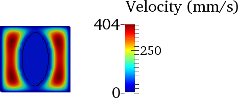
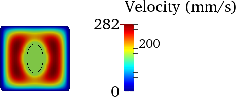
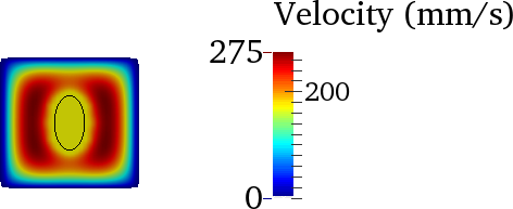
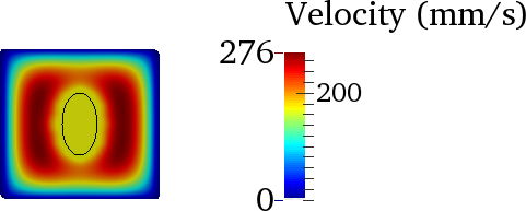
The more viscous liquid passes the junction and begins to detach from the top and bottom walls. The irregular shapes on the thread near the inlet are due to graphical artefacts. The contact line has a ‘V’-like shape which is strongly stretched at the bottom. After the detachment from the walls, the liquid becomes thinner to form a thread. To analyse the focusing process more clearly, four cross sections across the depth at different positions mm, mm, mm and mm (case 2) are shown in Fig. 2. The liquid L1 flows at an almost uniform velocity (plug flow) at the beginning of hydrodynamic focusing and is accelerated by the side flow. The thread becomes thinner (from Fig. 2(a) to Fig. 2(c)) and then is nearly stable (from Fig. 2(c) to Fig. 2(d)). Similarly, from mm to mm, the velocity contour changes dramatically at first, then slowly and at last becomes almost stable. Moreover, the flow of the liquid in the long microchannel is a plug flow and ensheathed by liquid .
It is noted that the cross section of the thread is an ellipse rather than a circle. The minor axis of the thread and the major axis of the thread along the flow direction up to the diverging point are plotted in Fig. 3. From Fig. 3, the stable minor axis and major axis of the thread produced by focusing are mm and mm for case 2. Besides, it suggests that liquid detaches completely from the walls near the position mm. The minor axis and major axis of the thread as well as the ratios , and for all 5 cases are listed in Table 3.

| cases | ||||||
|---|---|---|---|---|---|---|
| 1 (base case) | 0.0573 | 0.0836 | 0.2292 | 0.3344 | 0.69 | |
| 2 | 0.0565 | 0.103 | 0.226 | 0.412 | 0.55 | |
| 3 | 0.0578 | 0.057 | 0.2312 | 0.228 | 1.01 | |
| 4 | 0.088 | 0.111 | 0.352 | 0.444 | 0.793 | |
| 5 | 0.06 | 0.088 | 0.24 | 0.352 | 0.73 |
According to the velocity profile for the annular flow in a circular tube of diameter directly calculated from the Stokes equations (Joseph and Renardy, 1993), a simple scaling for the thread can be found with small threads and large viscosity ratios : . Although this analysis is only valid for a circular tube, Cubaud (Cubaud and Mason, 2009) suggests that the relationship between and is essentially the same for square tubes when and scales as for small threads. For the case of a square micro channel of width , for comparing circular diameter and square cross section instead of is used. It is noted that the thread is assumed circular, so is used as the diameter of the thread. Cubaud’s experiments (Cubaud and Mason, 2006a) suggest that the thread minor-axis (diameter) was independent of and follows . In Cubaud’s experiments they took photos from above with a high speed camera, so that only the minor-axis (diameter) of the thread could be measured (Thus it is not clear whether the thread cross section was circular or not). In Fig. 4, the estimating lines , and values , from our simulations are presented. When is small, the two power-law predictions are close. From Fig. 4, the slope of from our simulation results agrees well with both power-law relationships and , the minor axis (the thread width from the top view) is only dependent on the flow ratio . However for the major axis of the thread in Fig. 4, the situation seems more complicated in that depends on not only the flow rate ratio but also on other parameters such as the viscosity ratio . For the same , the lower viscosity ratio decreases the major axis and the thread cross section appears more circular.


We also note in Fig. 3 that the cross section of threads become almost stable at mm (case 2) and mm (case 3). The long focusing microchannel is necessary for fluids with a large viscosity ratio to produce a thread thin enough. Chung et al (2010) found the thread width also increased with increasing viscosity ratio and predicts the existence of the upper bound of for viscous folding. This is due to the short focusing microchannel, only in their study. Consequently, the hydrodynamic focusing procedure is not completely finished and the thread is too thick to undergo viscous folding or buckling instability in the diverging region.
3.2 Viscous folding
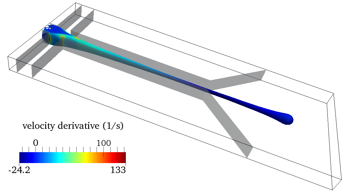
The thread produced by hydrodynamic focusing continues to flow in the diverging region and a folding instability appears due to the compressive stress. For our 5 simulation cases, different flow patterns has been observed. In the reference case 1 with as shown in Fig. 5, the thread begins to fold about an axis in the -direction in Fig. 5(b), and then the folding plane rotates in Fig. 5(c). In Fig. 5(d) the new folds appear mainly in the -direction. For case 5 in which only the diverging angle is changed from to , the flow pattern is similar to the reference case 1.
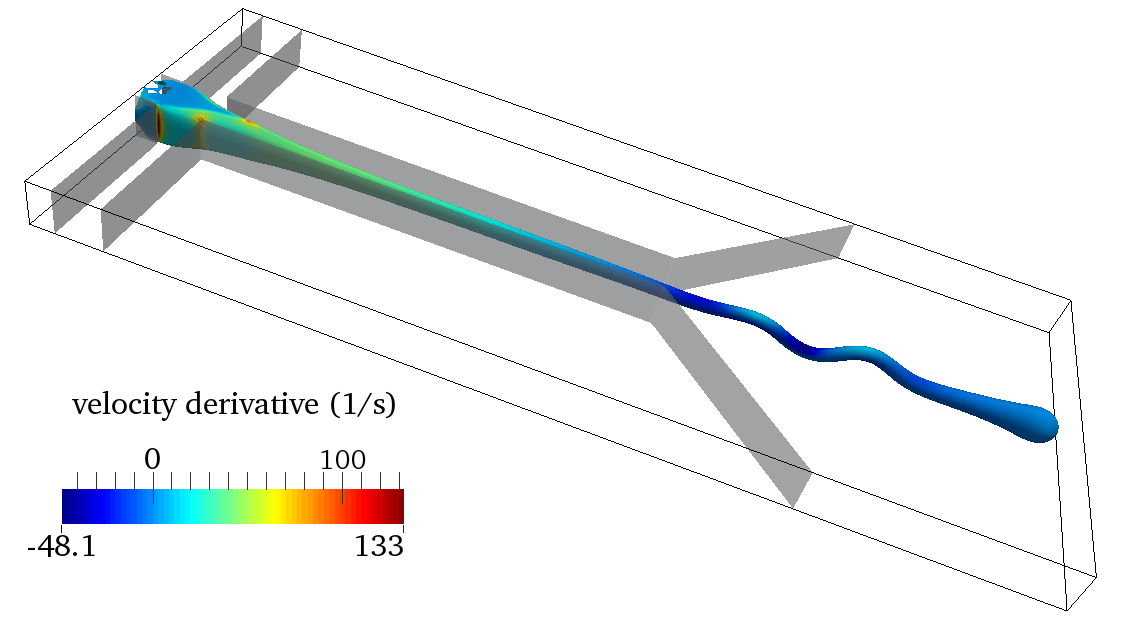
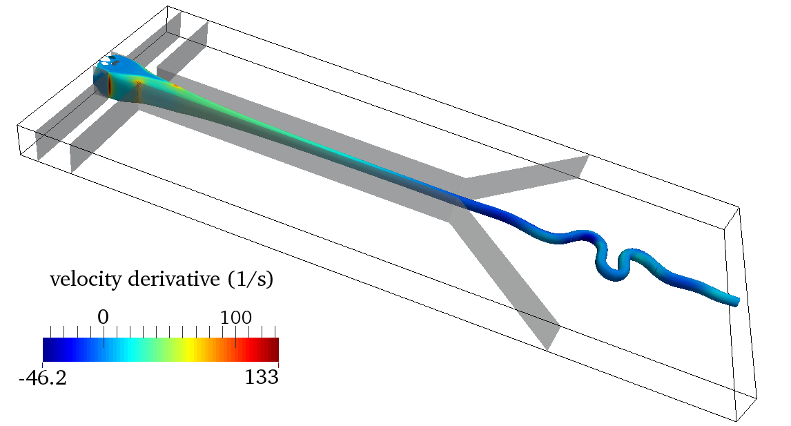
For simulation case 2 (), as shown in Fig. 6(a), the thread begins to fold in the -direction. The folding frequency and amplitude then vary slightly after the thread exits the computation domain in Fig. 6(b), and finally, the folding frequency and amplitude become stable in Fig. 6(d) and 6(e). It is noted that the folding only happens in the -direction in simulation case 2.
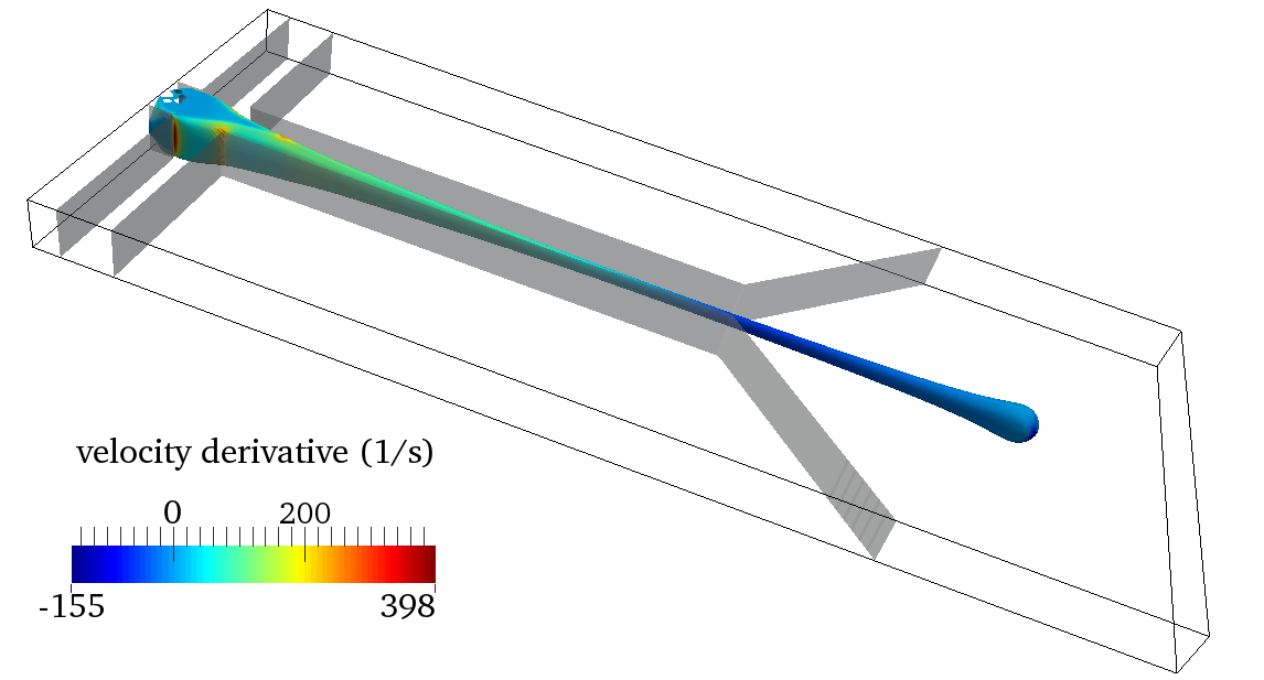
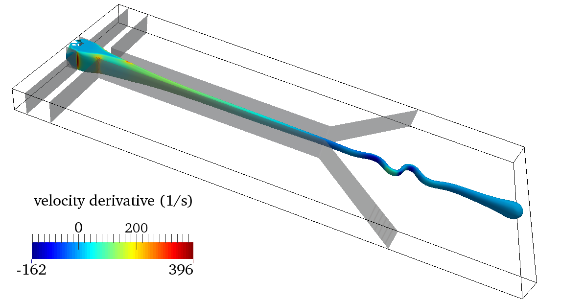
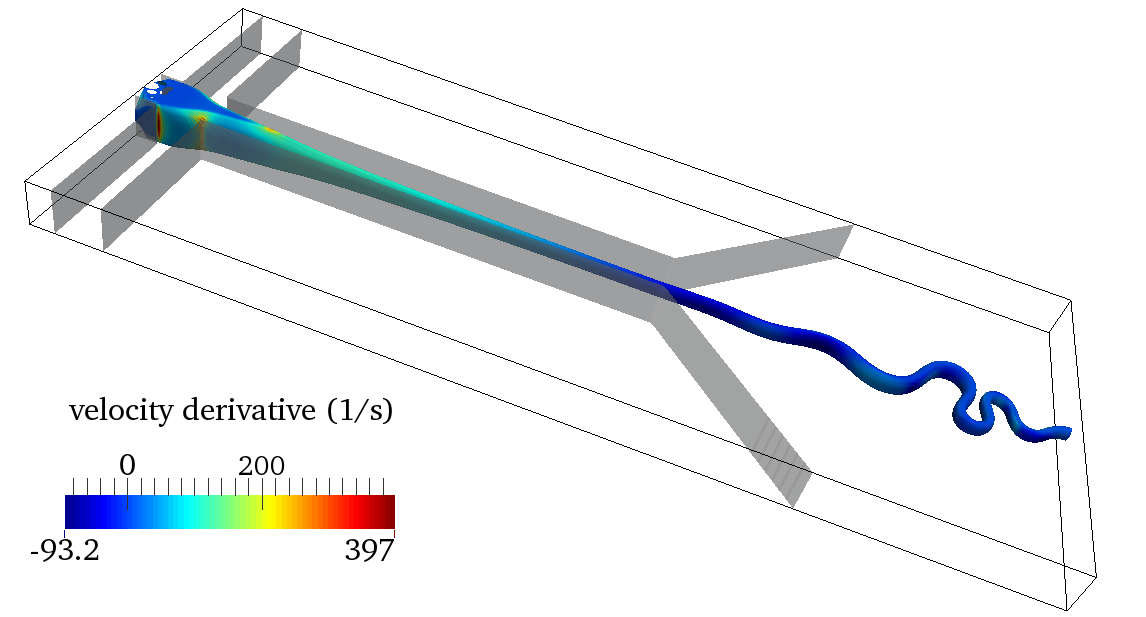
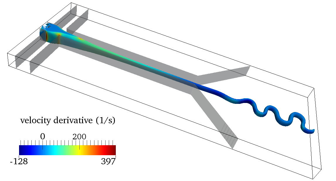
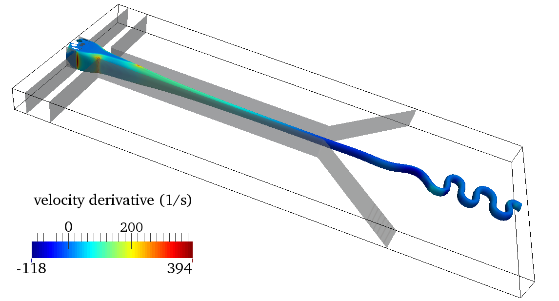
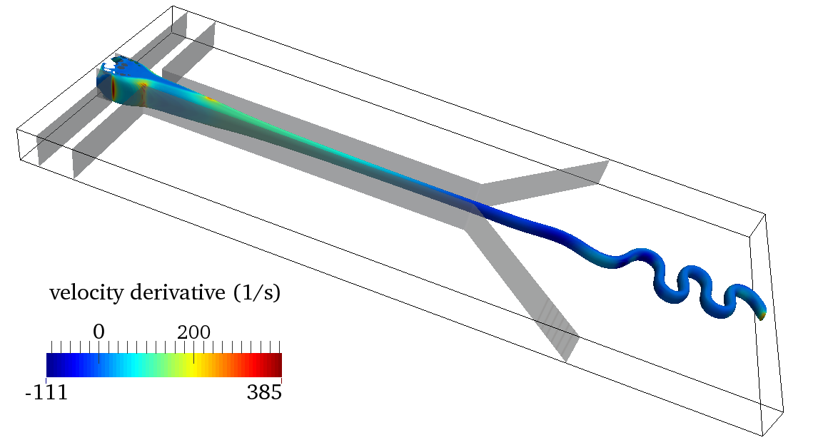
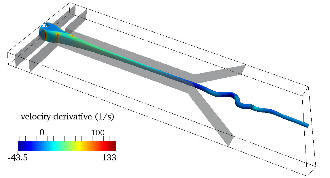
In case 3 with , the onset of folding appears in the -direction in Fig. 7(b). For this case, there is not only folding instability but also strong shrinking when the thread is subject to the compressive stress. The thread is squeezed, so that the thread becomes fatter and the folding wavelength decreases as the thread flows downstream (from Fig. 7(b) to 7(c)). Consequently, the amplitude of newly appearing folds decreases to zero slowly and its wavelength becomes larger. Finally, the folding phenomenon disappears and the thread is completely straight in Fig. 7(d).
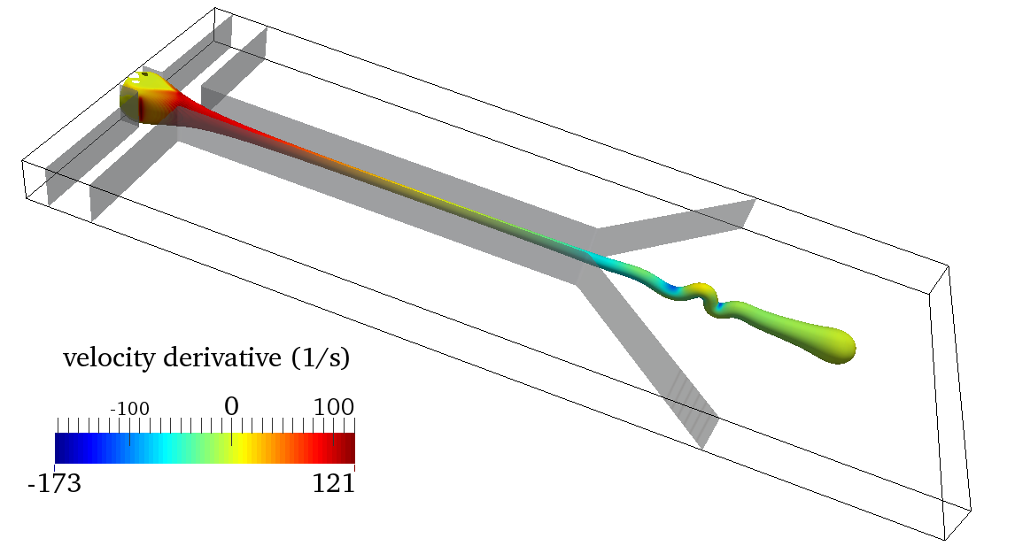
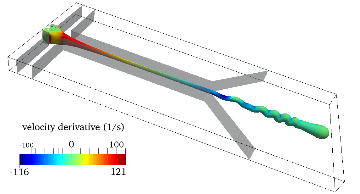
The folding is induced by the viscous compressional stress. The velocity of the flow in the long focusing channel and near the diverging point is nearly in the z-direction, i.e. . Thus the non-zero components in the viscous stress are
| (16) | ||||
| (17) | ||||
| (18) |
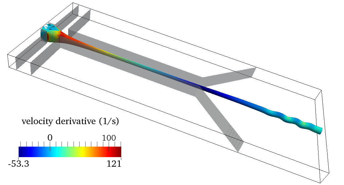
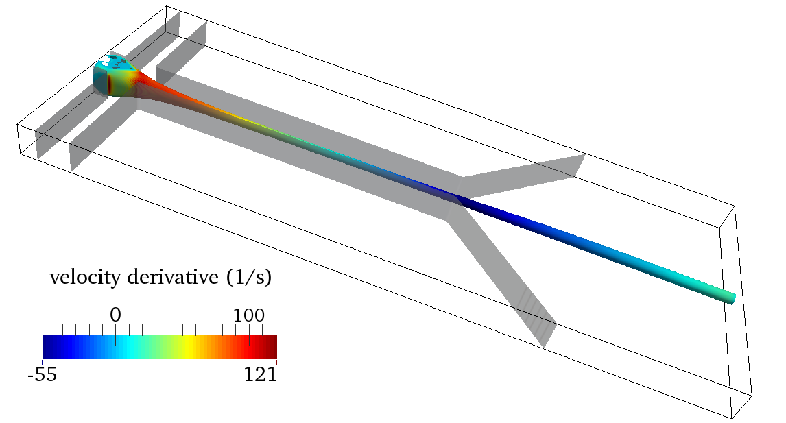
where is the viscosity of liquid or . On the cross section of the thread the viscous stress is longitudinal stress, due to the plug flow. In Chung’s study (Chung et al, 2010), the longitudinal stress is defined as along the centerline. In their Fig. 4(d) (Chung et al, 2010), the longitudinal stress is highly compressional. Here, our simulations are 3-dimensional, the longitudinal stress is proportional to the derivatives . The derivatives of the velocity with respect to along the thread are shown in Fig. 8, it is clear the longitudinal stress is compressional in the diverging region, especially near the diverging point.
On the thread interface, the viscous force per unit area by liquid can be obtained by , where is the unit normal vector to the interface. Since the major axis and minor axis become stable near the diverging point, the unit normal vector is in the - plane . Thus, the viscous force per unit area on the interface is
| (19) |
The viscous force on the interface is proportional to the normal derivative . Then the bending moment on the cross section of the thread induced by the viscous force on the interface can be calculated, it has two components
| (20) | ||||
| (21) |
Where the integrals are done along the bounding line of cross section , are the coordinates of the center on the cross section. Here the bending moment is presented by the integral part, i.e. and . For case 1 with Re, the bending moments of the thread and on the cross section at mm are plotted from the onset of the folding instability in Fig. 8(a). At first the moment dominates, the cross section rotates about the -axis resulting in folding in the -direction. And then the moment increases, the folding slowly transforms via twisting to folding in the -direction. When the ratio of the thread is much less than the moment is always very small compared to , so that the folding only appears in the -direction. This is just what we observe in simulation case 2 (similar bending moments over time are presented in Fig. 8(b)).


Due to the high viscosity contrast and very low Reynolds numbers involved, direct numerical simulations of this two-phase flow are very challenging and to our knowledge these are the first three-dimensional direct parallel numerical simulations of viscous threads in microchannels. However, since the computational time for these simulations is quite long, especially for such viscous threads, the simulations present only the early time onset of the buckling instability of the threads, thus long-time comparisons with experiments for quantities such as folding amplitude and frequency are limited.
4 Conclusions
The parallel code BLUE for multi-phase flows was used to simulate three-dimensional viscous folding in diverging microchannels. Liquid takes the form of a thin filament due to hydrodynamic focusing in the long channel that leads to the diverging region. The thread becomes unstable to a folding instability after its entry into the main chamber, due to the longitudinal compressive stress applied to it by the diverging flow of liquid . Given the long computation time for such a low Reynolds number flow, we were limited to a parameter study comprising five simulations in which the flow rate ratio, the viscosity ratio, the Reynolds number, and the shape of the channel were varied relative to a reference model.
During the hydrodynamic focusing, the shape and velocity of the thread vary dramatically at first, then evolve slowly and finally achieve a nearly stable state, which implies that the hydrodynamic focusing phase is complete in the sufficiently long focusing channel. Moreover, the cross section of the thread is elliptical rather than circular. There is a power law relation between the dimensionless minor axis and the flow ratio and our results are in good agreement with experimental and theoretical predictions of other researchers. For the major axis , the situation is more complicated. The lower viscosity ratio decreases the major axis and the thread cross section appears more circular. Additionally, the interfacial tension plays important role in the thread formation after the liquid detaches from walls. Future study will be undertaken to understand the role of interfacial tension on the major axis of the thread produced by hydrodynamic focusing and the following viscous folding instability.
Unlike the previous two-dimensional simulations of Chung et al (2010), our simulations are fully three-dimensional and thus do not constrain the axis along which the folding instability could occur. The initial folding axis can be either parallel or perpendicular to the narrow dimension of the chamber. In the former case, the folding slowly transforms via twisting to perpendicular folding, or may remain parallel. The direction of folding onset is determined by the velocity profile and the ellipticity of the thread cross section in the channel that feeds the diverging part of the cell.
Due to the high viscosity contrast and very low Reynolds numbers involved, direct numerical simulations of this two-phase flow are very challenging and to our knowledge these are the first three-dimensional direct parallel numerical simulations of viscous threads in microchannels. However, since the computational time for these simulations is quite long, especially for such viscous threads, the simulations present only the early time onset of the buckling instability of the threads, thus long-time comparisons with experiments for quantities such as folding amplitude and frequency are limited. In the future, more long-time simulations with a larger range of viscosity ratio, Reynolds number, flow rate ratio and with different channel geometries will be implemented in order that exhaustive comparisons with experiments can help in improving the understanding of viscous folding in microchannels.
Acknowledgements.
We thank N. Ribe and T. Cubaud for helpful discussions. This work was performed using high performance computing resources provided by the Institut du Developpement et des Ressources en Informatique Scientifique (IDRIS) of the Centre National de la Recherche Scientifique (CNRS). This research was supported by the Basic Science Research Program through the National Research Foundation of Korea (NRF) funded by the Ministry of Science, ICT and future planning (NRF-2014R1A2A1A11051346)References
- Bottausci et al (2004) Bottausci F, Mezić I, Meinhart CD, Cardonne C (2004) Mixing in the shear superposition micromixer: three-dimensional analysis. Philosophical Transactions of the Royal Society of London A: Mathematical, Physical and Engineering Sciences 362(1818):1001–1018
- Bringer et al (2004) Bringer MR, Gerdts CJ, Song H, Tice JD, Ismagilov RF (2004) Microfluidic systems for chemical kinetics that rely on chaotic mixing in droplets. Philosophical Transactions of the Royal Society of London A: Mathematical, Physical and Engineering Sciences 362(1818):1087–1104
- Chang et al (2007) Chang CC, Huang ZX, Yang RJ (2007) Three-dimensional hydrodynamic focusing in two-layer polydimethylsiloxane (pdms) microchannels. Journal of Micromechanics and Microengineering 17(8):1479
- Chen et al (2009) Chen Z, Bown M, O’Sullivan B, MacInnes J, Allen R, Mulder M, Blom M, van’t Oever R (2009) Performance analysis of a folding flow micromixer. Microfluidics and nanofluidics 6(6):763–774
- Chorin (1968) Chorin AJ (1968) Numerical solution of the navier-stokes equations. Mathematics of computation 22(104):745–762
- Chou et al (2001) Chou HP, Unger MA, Quake SR (2001) A microfabricated rotary pump. Biomedical Microdevices 3(4):323–330
- Chung et al (2010) Chung C, Choi D, Kim JM, Ahn KH, Lee SJ (2010) Numerical and experimental studies on the viscous folding in diverging microchannels. Microfluidics and Nanofluidics 8(6):767–776
- Cruickshank (1988) Cruickshank J (1988) Low-reynolds-number instabilities in stagnating jet flows. Journal of fluid mechanics 193:111–127
- Cruickshank and Munson (1982a) Cruickshank J, Munson B (1982a) An energy loss coefficient in fluid buckling. Physics of Fluids (1958-1988) 25(11):1935–1937
- Cruickshank and Munson (1982b) Cruickshank J, Munson B (1982b) The viscous-gravity jet in stagnation flow. Journal of Fluids Engineering 104(3):360–362
- Cruickshank and Munson (1983) Cruickshank J, Munson B (1983) A theoretical prediction of the fluid buckling frequency. Physics of Fluids (1958-1988) 26(4):928–930
- Cubaud and Mason (2009) Cubaud T, Mason T (2009) High-viscosity fluid threads in weakly diffusive microfluidic systems. New Journal of Physics 11(7):075,029
- Cubaud and Mason (2006a) Cubaud T, Mason TG (2006a) Folding of viscous threads in diverging microchannels. Physical review letters 96(11):114,501
- Cubaud and Mason (2006b) Cubaud T, Mason TG (2006b) Folding of viscous threads in microfluidics. Physics of Fluids 18(9):091,108
- Cubaud et al (2005) Cubaud T, Tatineni M, Zhong X, Ho CM (2005) Bubble dispenser in microfluidic devices. Physical Review E 72(3):037,302
- Griffiths and Turner (1988) Griffiths R, Turner J (1988) Folding of viscous plumes impinging on a density or viscosity interface. Geophysical Journal International 95(2):397–419
- Habibi et al (2014) Habibi M, Hosseini S, Khatami M, Ribe N (2014) Liquid supercoiling. Physics of Fluids (1994-present) 26(2):024,101
- Harlow et al (1965) Harlow FH, Welch JE, et al (1965) Numerical calculation of time-dependent viscous incompressible flow of fluid with free surface. Physics of fluids 8(12):2182
- Joseph and Renardy (1993) Joseph DD, Renardy Y (1993) Fundamentals of two-fluid dynamics: Part II: Lubricated Transport, Drops and Miscible Liquids. Springer Science & Business Media
- Kang et al (2007a) Kang TG, Hulsen MA, Anderson PD, den Toonder JM, Meijer HE (2007a) Chaotic advection using passive and externally actuated particles in a serpentine channel flow. Chemical Engineering Science 62(23):6677–6686
- Kang et al (2007b) Kang TG, Hulsen MA, Anderson PD, Toonder JMd, Meijer HE (2007b) Chaotic mixing induced by a magnetic chain in a rotating magnetic field. Physical Review-Section E-Statistical Nonlinear and Soft Matter Physics 76(6):66,303–66,303
- Kwak and Lee (2003) Kwak DY, Lee JS (2003) Multigrid algorithm for cell-centred finite difference method ii : Discontinuous coefficient case. Department of Mathematics, KAIST, Taejon Korea pp 305–701
- Lee et al (2006) Lee GB, Chang CC, Huang SB, Yang RJ (2006) The hydrodynamic focusing effect inside rectangular microchannels. Journal of Micromechanics and Microengineering 16(5):1024
- Mahadevan et al (1998) Mahadevan L, Ryu WS, Samuel AD (1998) Fluid’rope trick’investigated. Nature 392(6672):140–140
- Maleki et al (2004) Maleki M, Habibi M, Golestanian R, Ribe N, Bonn D (2004) Liquid rope coiling on a solid surface. Physical review letters 93(21):214,502
- Meleson et al (2004) Meleson K, Graves S, Mason TG (2004) Formation of concentrated nanoemulsions by extreme shear. Soft Materials 2(2-3):109–123
- Paik et al (2003a) Paik P, Pamula VK, Fair RB (2003a) Rapid droplet mixers for digital microfluidic systems. Lab on a Chip 3(4):253–259
- Paik et al (2003b) Paik P, Pamula VK, Pollack MG, Fair RB (2003b) Electrowetting-based droplet mixers for microfluidic systems. Lab on a Chip 3(1):28–33
- Peskin (1977) Peskin CS (1977) Numerical analysis of blood flow in the heart. Journal of computational physics 25(3):220–252
- Pollack et al (2002) Pollack M, Shenderov A, Fair R (2002) Electrowetting-based actuation of droplets for integrated microfluidics. Lab on a Chip 2(2):96–101
- Ribe (2004) Ribe NM (2004) Coiling of viscous jets. In: Proceedings of the Royal Society of London A: Mathematical, Physical and Engineering Sciences, vol 460, pp 3223–3239
- Ribe et al (2006) Ribe NM, Lister JR, Chiu-Webster S (2006) Stability of a dragged viscous thread: Onset of “stitching” in a fluid-mechanical “sewing machine”. Physics of Fluids 18(12):124,105
- Rida and Gijs (2004) Rida A, Gijs M (2004) Manipulation of self-assembled structures of magnetic beads for microfluidic mixing and assaying. Analytical chemistry 76(21):6239–6246
- Shin and Juric (2007) Shin S, Juric D (2007) High order level contour reconstruction method. Journal of mechanical science and technology 21(2):311–326
- Shin and Juric (2009a) Shin S, Juric D (2009a) A hybrid interface method for three-dimensional multiphase flows based on front tracking and level set techniques. International Journal for Numerical Methods in Fluids 60(7):753–778
- Shin and Juric (2009b) Shin S, Juric D (2009b) Simulation of droplet impact on a solid surface using the level contour reconstruction method. Journal of mechanical science and technology 23(9):2434–2443
- Shin et al (2014) Shin S, Chergui J, Juric D (2014) A solver for massively parallel direct numerical simulation of three-dimensional multiphase flows. arXiv preprint arXiv:14108568
- Simonnet and Groisman (2005) Simonnet C, Groisman A (2005) Two-dimensional hydrodynamic focusing in a simple microfluidic device. Applied Physics Letters 87(11):114,104
- Skorobogatiy and Mahadevan (2000) Skorobogatiy M, Mahadevan L (2000) Folding of viscous sheets and filaments. EPL (Europhysics Letters) 52(5):532
- Stiles et al (2005) Stiles T, Fallon R, Vestad T, Oakey J, Marr D, Squier J, Jimenez R (2005) Hydrodynamic focusing for vacuum-pumped microfluidics. Microfluidics and Nanofluidics 1(3):280–283
- Stroock et al (2002a) Stroock AD, Dertinger SK, Ajdari A, Mezić I, Stone HA, Whitesides GM (2002a) Chaotic mixer for microchannels. Science 295(5555):647–651
- Stroock et al (2002b) Stroock AD, Dertinger SK, Whitesides GM, Ajdari A (2002b) Patterning flows using grooved surfaces. Analytical Chemistry 74(20):5306–5312
- Taylor (1969) Taylor G (1969) Instability of jets, threads, and sheets of viscous fluid. In: Applied Mechanics, Springer, pp 382–388
- Tchavdarov et al (1993) Tchavdarov B, Yarin A, Radev S (1993) Buckling of thin liquid jets. Journal of Fluid Mechanics 253:593–615
- Tome and Mckee (1999) Tome MF, Mckee S (1999) Numerical simulation of viscous flow: buckling of planar jets. International journal for numerical methods in fluids 29(6):705–718
- Utada et al (2005) Utada A, Lorenceau E, Link D, Kaplan P, Stone H, Weitz D (2005) Monodisperse double emulsions generated from a microcapillary device. Science 308(5721):537–541
- Wu and Nguyen (2005) Wu Z, Nguyen NT (2005) Hydrodynamic focusing in microchannels under consideration of diffusive dispersion: theories and experiments. Sensors and Actuators B: Chemical 107(2):965–974