2 School of Physics and Astronomy, University of Leeds, Leeds, LS2 9JT, UK
3 Max Planck Institute for Radioastronomy, Auf dem Hügel 69, 53121 Bonn, Germany
4 International Centre for Radio Astronomy Research, Curtin University, GPO Box U1987, Perth WA 6845, Australia
5 National Radio Astronomy Observatory, P.O. Box O, 1003 Lopezville Road, Socorro, NM 87801, USA
6 Department of Physics and Astronomy, University of Calgary, 2500 University Drive NW, Calgary AB, T2N 1N4, Canada
7 Department of Astronomy, University of Massachusetts, Amherst, MA 01003-9305, USA
8 Jet Propulsion Laboratory, California Institute of Technology, 4800 Oak Grove Drive, Pasadena, CA 91109, USA
9 Department of Physics and Astronomy, West Virginia University, Morgantown, WV 26506, USA
10 Astrophysics Research Institute, Liverpool John Moores University, 146 Brownlow Hill, Liverpool L3 5RF, UK
11 Universität Heidelberg, Zentrum für Astronomie, Institut für Theoretische Astrophysik, Albert-Ueberle-Str. 2, D-69120 Heidelberg, Germany
12 I. Physikalisches Institut, University of Cologne, Zülpicher Str. 77, 50937 Köln, Germany
13 Research School of Astronomy and Astrophysics, The Australian National University, Canberra, ACT, Australia
14 Jodrell Bank Centre for Astrophysics, School of Physics and Astronomy, The University of Manchester, Oxford Road, Manchester,M13 9PL, UK
15 Department of Physics, Indian Institute of Science, Bangalore 560012, India
16 National Astronomical Observatory of Japan, Chile Observatory, 2-21-1 Osawa, Mitaka, Tokyo 181-8588, Japan
17 School of Physical Sciences, University of Kent, Ingram Building, Canterbury, Kent CT2 7NH, UK
The HI/OH/Recombination line survey of the inner Milky Way (THOR) ††thanks: Based on observations carried out with the Karl Jansky Very Large Array (VLA).
Abstract
Context. The past decade has witnessed a large number of Galactic plane surveys at angular resolutions below . However, no comparable high-resolution survey exists at long radio wavelengths around 21 cm in line and continuum emission.
Aims. We remedy this situation by studying the northern Galactic plane at 20′′ resolution in emission of atomic, molecular, and ionized gas.
Methods. Employing the Karl G. Jansky Very Large Array (VLA) in the C-array configuration and a large program, we observe the HI 21 cm line, four OH lines, nineteen H radio recombination lines as well as the continuum emission from 1 to 2 GHz in full polarization over a large part of the first Galactic quadrant.
Results. Covering Galactic longitudes from 14.5 to 67.4 deg and latitudes between deg, we image all of these lines and the continuum at 20′′ resolution. These data allow us to study the various components of the interstellar medium (ISM): from the atomic phase, traced by the HI line, to the molecular phase, observed by the OH transitions, to the ionized medium, revealed by the cm continuum and the H radio recombination lines. Furthermore, the polarized continuum emission enables magnetic field studies. In this overview paper, we discuss the survey outline and present the first data release as well as early results from the different datasets. We now release the first half of the survey; the second half will follow later after the ongoing data processing has been completed. The data in fits format (continuum images and line data cubes) can be accessed through the project web-page http://www.mpia.de/thor.
Conclusions. The HI/OH/Recombination line survey of the Milky Way (THOR) opens a new window to the different parts of the ISM. It enables detailed studies of molecular cloud formation, conversion of atomic to molecular gas, and feedback from Hii regions as well as the magnetic field in the Milky Way. It is highly complementary to other surveys of our Galaxy, and comparing the different datasets will allow us to address many open questions.
Key Words.:
Stars: formation – ISM: clouds – ISM: structure – ISM: kinematics and dynamic – ISM: magnetic fields – stars: evolution1 Introduction
Over the past decade, the Galactic plane was surveyed comprehensively from near-infrared to cm wavelengths. These surveys enable investigations of not only individual local phenomena such as stars, clusters, ionized gas and molecular or atomic clouds, but studies of our Galaxy as a whole, and we can compare the results to extragalactic studies (see, e.g., Taylor et al. 2003; Churchwell et al. 2009; Carey et al. 2009; Schuller et al. 2009; Anderson et al. 2011; Walsh et al. 2011; Beuther et al. 2012; Ragan et al. 2014; Wang et al. 2015; Goodman et al. 2014; Reid et al. 2014; Abreu-Vicente et al. 2016). Particularly important for a general understanding of the different physical processes is the multiwavelength approach because different surveys trace different components of the interstellar medium (ISM) and stellar populations, as well as varying temperature regimes and physical processes. Earlier ideas for such a multiwavelength survey approach were promoted by the Canadian Galactic Plane Survey (Taylor et al., 2003), for example. The different phases (atomic, molecular, or ionized gas and dust) are not isolated, but interact and, maybe even more importantly, they change from one phase to the other in the natural matter cycle of the ISM. It is therefore important for our understanding of ISM dynamics and star formation to have surveys at comparable angular resolution.
While most of the infrared to mm Galactic plane surveys have an angular resolution better than , the existing HI Very Large Array Galactic Plane Survey (VGPS) survey conducted with the Very Large Array (VLA) in its compact D-configuration has an angular resolution of only (Stil et al., 2006). For comparison, the most recent single-dish survey of HI with the Effelsberg telescope has an angular resolution of (Winkel et al., 2016). Even though the VLA D-configuration as well as single-dish HI surveys are appropriate for studying atomic Galactic structure on large scales, they are less useful for the direct comparison with the other existing surveys mentioned above. For example, previous 60′′ resolution observations of HI and CO emissions lines showed that large-scale atomic gas envelopes and atomic gas flows in the surrounding environments are needed to form denser molecular gas, and subsequently dense core and massive stars (e.g., Nguyen Luong et al. 2011; Motte et al. 2014). However, these data could not yet be used to study the interaction between the atomic and the dense molecular gas structures that may occur on significantly smaller scales (see, e.g., the recent 870 m dust continuum emission Galactic plane survey ATLASGAL at resolution, Schuller et al. 2009). For reference, we mention that 0.5 pc corresponds to at a typical molecular cloud distance of 4 kpc.
Furthermore, the new capabilities of the WIDAR correlator at the VLA allow us to observe many spectral lines simultaneously, in particular several molecular OH transitions, a series of H radio recombination lines (RRLs, ), and the continuum emission. Combining these data with the HI observations probes the transition of matter in the ISM from the diffuse neutral atomic to the dense molecular and the ionized gas components and back. This combined approach is followed in The HI/OH/Recombination line survey of the Milky Way (THOR) we present here. These new THOR C-configuration HI data ( resolution corresponding to linear scales of 0.2-0.3 pc at typical distances of 3 kpc), when combined with the existing D-configuration and GBT (Green Bank Telescope) observations to include the larger-scale emission (Stil et al., 2006), enable us to address many questions associated with atomic hydrogen from large-scale Galactic structure and cloud formation processes down to the scales of individual star-forming regions. At the same time, the OH, RRLs, and continuum data provide a more complete picture of the Galactic ISM.
This paper presents an overview of THOR and the first data release. The motivation and goals of the survey are described in Sect. 2, and the parameters of the survey are presented in Sect. 3. The observation details and data analysis are given in Sect. 4, while initial results from this survey are presented in Sect. 5. Finally, the potential of this survey and the future possibilities are discussed in Sect. 6, and a summary is presented in Sect. 7.
2 Goals of the survey
2.1 Atomic to molecular hydrogen transition of clouds
Several cloud formation scenarios favor converging flows in which large-scale gas streams collide and form density enhancements in which the conversion from atomic to molecular hydrogen is thought to mainly take place (e.g., Ballesteros-Paredes et al. 1999; Hartmann et al. 2001; Vázquez-Semadeni et al. 2006; Hennebelle & Audit 2007; Hennebelle et al. 2008; Heitsch et al. 2008; Banerjee et al. 2009; Ballesteros-Paredes et al. 2011; Clark et al. 2012; Dobbs et al. 2014). These simulations predict that before molecular gas forms, the medium remains in an atomic phase for several million years (e.g., Elmegreen 2007; Heitsch & Hartmann 2008; Clark et al. 2012). Hydrodynamical simulations coupled with chemical networks and radiative transfer calculations provide predictions of spectral line parameters (e.g., line widths, spatially resolved kinematics) and physical and structural properties (e.g., probability density functions) of the different phases of the ISM.
To investigate current cloud formation models, a sensitive characterization of the atomic HI phase at an angular resolution comparable to the molecular gas is therefore mandatory. HI absorption line studies at high angular and spectral resolution (FWHM of the cold neutral medium (CNM) in HI at 100 K 2.2 km s-1) have proven to be an excellent tool for studying the CNM and its association with dense molecular gas cores (e.g., Heiles & Troland 2003; Dickey et al. 2003; Li & Goldsmith 2003; Goldsmith & Li 2005; Gibson et al. 2005a; Krčo et al. 2008; Kanekar et al. 2011; Roy et al. 2013a, b; Liszt 2014; Lee et al. 2015; Murray et al. 2015). Combining the HI absorption lines with the simultaneously observed molecular OH absorption or emission as well as other tracers of the cold, dense ISM such as the submm continuum (e.g., the ATLASGAL survey, Schuller et al. 2009) allow studying the interplay and accretion of the atomic and molecular gas from the larger cloud-scales (10 pc) to the smaller core-scales (0.25-0.5 pc) (e.g., Goldbaum et al. 2011; Smith et al. 2012). Considering the sensitivity to both small- and large-scale HI emission, this survey will also be very useful for studying the second-order statistics, for instance, the angular correlation function or power spectrum, of the cold atomic ISM, and thus probe turbulence at these scales.
Complementary molecular gas information is available through several surveys such as the CO emission from the JCMT CO survey (Dempsey et al., 2013; Rigby et al., 2016), the Galactic Ring Survey (Jackson et al., 2006), the Exeter-FCRAO CO Galactic Plane survey (Brunt et al. in prep.), and dense gas studies through spectroscopic follow-ups of the ATLASGAL and BGPS (sub)mm continuum surveys (e.g., Schlingman et al. 2011; Wienen et al. 2012; Shirley et al. 2013; Giannetti et al. 2014).
THOR facilitates characterizing the phase transition from atomic to molecular gas in detail, directly linking models with observations, and comparing the results with extragalactic studies (e.g., Hennebelle et al. 2007; Glover et al. 2010; Glover & Mac Low 2011; Shetty et al. 2011; Walter et al. 2008; Leroy et al. 2008; Smith et al. 2014; Walch et al. 2015; Girichidis et al. 2016; Bertram et al. 2016).
2.2 OH maser and thermal emission and absorption
We conduct simultaneous observations of four hydroxyl lines. Hydroxyl (OH) has a remarkably constant abundance relative to molecular hydrogen in diffuse and translucent molecular clouds up to column densities of (Lucas & Liszt, 1996). These observations yield sensitive information on ISM gas with properties in between cold neutral atomic and dense molecular gas that so far has only been sparsely studied. Combining the information from the four hyperfine structure lines at 1612, 1665, 1667, and 1720 MHz (relative intensities 1:5:9:1) can constrain the OH excitation behavior and deliver local thermodynamic equilibrium (LTE) estimates of column densities, as well as kinematics and neutral particle and electron densities (Nguyen-Q-Rieu et al., 1976; Elitzur, 1976; Guibert et al., 1978).
In addition to the thermal OH emission and absorption, we can identify a flux-limited sample of OH masers at 1612, 1665, 1667, and 1720 MHz in the northern Milky Way. While previous surveys typically covered only one line, observing all four maser lines is particularly interesting since they trace different physical and evolutionary phases (see Sect. 5.3). In combination with the southern hemisphere single-dish OH survey SPLASH (Dawson et al., 2014), these observations will show the full population of OH masers in the Galaxy.
2.3 H radio recombination lines
Radio recombination lines trace the ionized gas of Hii regions. We are able to study its kinematics in a spatially resolved fashion. Combining the emission from the ionized gas with that of the atomic (HI) and molecular components (e.g., JCMT CO survey, Dempsey et al. 2013; Galactic Ring Survey, Jackson et al. 2006; or dense gas surveys, Schlingman et al. 2011; Wienen et al. 2012; Shirley et al. 2013) and the stellar components observable by Spitzer allows us to study the expansion of ionized regions in the surrounding medium and the (non-)association with young embedded stellar populations. Such a dataset enables investigating triggering processes in star formation as well as general feedback processes of the different phases of the ISM.
2.4 Continuum emission
Observing the continuum emission from 1 to 2 GHz facilitates the derivation of spectral indices for thousands of sources ranging from Hii regions to background galaxies. With these data we can characterize the physical properties of the gas (e.g., electron number densities), differentiate free-free from synchrotron emission, and determine whether the gas is optically thin or thick. These data may also be used to derive the Galactic continuum emission fluctuation power spectrum of the diffuse component, which is related to the density and magnetic field fluctuations (e.g., Goldreich & Sridhar 1995; Iacobelli et al. 2013). Characterizing the low-frequency continuum is interesting in itself in addition to being useful for building up foreground models for ongoing and future low-frequency observations targeting cosmological signals. Furthermore, we can resolve the kinematic distance ambiguity for HII regions using HI absorption against the Hii region broadband continuum emission (e.g., Kolpak et al. 2003; Anderson & Bania 2009). Compared to the VGPS, we have better sensitivity to small-scale structure, which permits this analysis for fainter Hii regions in more complicated zones of star formation. While the Multi-Array Galactic Plane Imaging Survey (MAGPIS, Helfand et al. 2006) achieves an even higher angular resolution, THOR is the only available L-band continuum survey that allows us to derive the spectral index information.
2.5 Polarization and magnetic field measurements
Obtaining the linear polarization information for the continuum facilitates the identification of distant young supernova remnants. In addition, the Faraday effect, describing the rotation of the plane of polarization that is due to magnetic fields along the line of sight, can be used to determine magnetic field properties on large and small scales toward polarized Galactic and extragalactic sources. The data have higher angular resolution and L-band frequency coverage than existing surveys. The higher angular resolution (1 pc at a distance of 10 kpc) will allow us to identify young supernova remnants in crowded star formation regions where surveys like the NRAO VLA Sky Survey (NVSS, Condon et al. 1998) suffer from confusion with bright thermal emission. Moreover, a smaller beam size reduces depolarization of resolved sources by differential Faraday rotation across the beam.
Integrating the polarized source counts of Hales et al. (2014), who had similar resolution at 1.4 GHz, we estimate that 490 extragalactic sources with a polarized flux density greater than 3 mJy () exist in the 132 square degree survey area. This may be compared with the 194 sources measured by Van Eck et al. (2011), who targeted polarized sources selected from the NVSS. The difference in sample size results from a combination of factors that include bandwidth depolarization and confusion with bright emission in the NVSS, a larger portion of resolved sources at higher angular resolution, and specific target selection criteria adopted by Van Eck et al. (2011). THOR will increase the sample of extragalactic sources at very low Galactic latitude that probe the entire Milky Way disk.
The intrinsic polarization of resolved supernova remnants provides information on the magnetic field structure and the degree of order in the magnetic field. The observed polarization is affected by Faraday rotation by the (turbulent) foreground, and possibly internal Faraday rotation. Beyond traditional measurements of Faraday rotation that yield a single rotation measure, the wide frequency coverage of the data allows us to investigate higher order effects that occur when different parts of the source experience different amounts of Faraday rotation (e.g., Farnsworth et al. 2011). For example, differential Faraday rotation across the synthesized beam by a turbulent plasma in the line of sight to a resolved source results in wavelength-dependent depolarization that can be detected in broad-band polarimetric data. Modeling these effects will help to reconstruct the intrinsic polarization of the supernova remnant, and provides information about the turbulent medium in which the Faraday rotation occurs.
3 Survey
This THOR 21 cm line and continuum survey is a Large Program at the Karl G. Jansky Very Large Array with approximately 215 hours of observing time in the C-array configuration (Perley et al., 2011). The primary beam size over the L-band from 1 to 2 GHz changes by a factor 2, and the absolute areal coverage of THOR depends slightly on the spectral window considered. The approximate areal coverage of THOR is 132 square degrees from 14.5 to 67.25 degrees in Galactic longitude and degrees in Galactic latitude. This coverage is based on scientific as well as technical arguments: Scientifically, this part of the Milky Way covers a large portion of the inner Milky Way that also includes the bar-spiral interface. Hence, very different star formation environments are observable from very active almost starburst-like regions (e.g., W43) out to less active environments in the larger longitude range. From a technical point of view, this is approximately the same coverage as the previous HI and 1.4 GHz continuum survey VGPS. This enables us to combine the new THOR observations with the VGPS data to recover signal over a wider range of spatial scales. The survey as a whole was conducted during three campaigns. It started with a pilot study in 2012 that targeted mainly four square degrees around the mini-starburst W43 (legacy id AB1409). Based on the very positive initial results from this pilot study (e.g., Bihr et al. 2015; Walsh et al. 2016), we conducted the first half of the survey in 2013 (phase 1, id AB1447). It covered the longitude range between 14.5 and 37.9 degrees and a smaller strip from 47.1 to 51.2 degrees targeting the Sagittarius arm tangential point, including the star-forming region W51. The combined continuum data of THOR in the VLA C-configuration with previous VGPS data (VLA D-configuration plus single-dish GBT observations, Stil et al. 2006) of this first half of the survey are shown in Figs. 7 and 8. The second half of the survey was observed from the end of 2014 to the beginning of 2015 (phase 2, id AB1513). While we report in this paper the survey, calibration and imaging strategies of the full survey, we present here only images and early results from the first half of the survey because of the time-consuming nature of the imaging process. The remaining data products will then be published in the near future.
We require an angular resolution of so that the data are comparable to other Galactic plane surveys (e.g., ATLASGAL, Schuller et al. 2009). This goal requires in the L-band (between 1 and 2 GHz frequency) observations in the VLA C-configuration. To image the most extended component, the atomic HI, and also for the 1.4 GHz continuum, these data can be combined with the previous VGPS survey data (Stil et al., 2006). For the remaining data, we concentrate on observations in the C-configuration alone.
The new WIDAR correlator is extremely flexible, facilitating a broad coverage of frequencies as well as zooms into many bands. The spectral setup is designed with three main goals in mind: (a) to spectrally resolve the HI and OH lines at comparable resolution (1.5 km s-1) as the previous VGPS survey did for the HI line. This is a good compromise between signal-to-noise ratio and spectral resolving power for the thermal HI lines. (b) The second goal is to observe the full L-band bandpass from 1 to 2 GHz in full polarization. (c) And finally, we aim to cover as many radio recombination lines as possible (19) at intermediate spectral resolution because the ionized lines have broader thermal line width (on the order of 20 km s-1). The spectral set up of the survey, shown in Table 1, was decided based on these goals. The setup was slightly different for the pilot study, phases 1 and 2 (marked as phase p, 1 and 2, respectively, in the table), as a result of adjustment and optimization of observation strategy after the pilot study.
| cent. | widtha | phaseb | RFIc | |||
|---|---|---|---|---|---|---|
| (MHz) | (MHz) | (kHz) | (km s-1) | |||
| HI | 1420.406 | 2 | 1.95 | 0.41 | p | |
| HI | 1420.406 | 2 | 3.91 | 0.82 | 1,2 | |
| OH1 | 1612.231 | 2 | 3.91 | 0.73 | p | |
| OH1 | 1612.231 | 2 | 7.81 | 1.46 | 1,2 | |
| OH2/3 | 1665.402 | 4 | 3.91 | 0.70 | p | |
| OH2 | 1665.402 | 2 | 7.81 | 1.40 | 1d | |
| OH2/3 | 1665.402 | 4 | 7.81 | 1.40 | 2 | |
| OH4 | 1720.530 | 2 | 3.91 | 0.68 | p | |
| OH4 | 1720.530 | 2 | 7.81 | 1.36 | 1,2 | |
| cont1 | 1052 | 128 | 2000 | 570 | p,1,2 | |
| cont2 | 1180 | 128 | 2000 | 508 | p,1,2 | x |
| cont3 | 1308 | 128 | 2000 | 459 | p,1,2 | |
| cont4 | 1436 | 128 | 2000 | 418 | p,1,2 | |
| cont5 | 1564 | 128 | 2000 | 384 | p,1,2 | x |
| cont6 | 1692 | 128 | 2000 | 355 | p,1,2 | |
| cont7 | 1820 | 128 | 2000 | 330 | p,1,2 | |
| cont8 | 1948 | 128 | 2000 | 308 | p,1,2 | |
| H186 | 1013.767 | 4 | 31.25 | 9.2 | p | |
| H186 | 1013.767 | 2 | 15.63 | 4.6 | 1,2 | |
| H178 | 1156.299 | 4 | 31.25 | 8.1 | p | |
| H178 | 1156.299 | 2 | 15.63 | 4.1 | 1,2 | |
| H176 | 1196.028 | 4 | 31.25 | 7.8 | p | |
| H176 | 1196.028 | 2 | 15.63 | 3.9 | 1,2 | |
| H175 | 1216.590 | 4 | 31.25 | 7.7 | p | |
| H173 | 1259.150 | 2 | 15.63 | 3.7 | 1,2 | x |
| H172 | 1281.175 | 4 | 31.25 | 7.3 | p | x |
| H172 | 1281.175 | 2 | 15.63 | 3.7 | 1,2 | x |
| H171 | 1303.718 | 4 | 31.25 | 7.2 | p | |
| H171 | 1303.718 | 2 | 15.63 | 3.6 | 1,2 | |
| H170 | 1326.792 | 4 | 31.25 | 7.1 | p | |
| H170 | 1326.792 | 2 | 15.63 | 3.5 | 1,2 | |
| H169 | 1350.414 | 4 | 31.25 | 6.9 | p | x |
| H169 | 1350.414 | 2 | 15.63 | 3.5 | 1 | x |
| H168 | 1374.601 | 4 | 31.25 | 6.8 | p | |
| H168 | 1374.601 | 2 | 15.63 | 3.4 | 1,2 | |
| H167 | 1399.368 | 4 | 31.25 | 6.7 | p | |
| H167 | 1399.368 | 2 | 15.63 | 3.4 | 1,2 | x |
| H166 | 1424.734 | 4 | 31.25 | 6.6 | p | |
| H166 | 1424.734 | 2 | 15.63 | 3.3 | 1,2 | |
| H165 | 1450.716 | 4 | 31.25 | 6.5 | p | |
| H165 | 1450.716 | 2 | 15.63 | 3.2 | 1,2 | |
| H161 | 1561.203 | 2 | 15.63 | 3.0 | 1 | x |
| H158 | 1651.541 | 2 | 15.63 | 2.8 | 1,2 | |
| H156 | 1715.673 | 2 | 15.63 | 2.7 | 1,2 | |
| H155 | 1748.986 | 2 | 15.63 | 2.7 | 1,2 | |
| H154 | 1783.168 | 2 | 15.63 | 2.6 | 1,2 | |
| H153 | 1818.246 | 2 | 15.63 | 2.6 | 1,2 | |
| H152 | 1854.250 | 2 | 15.63 | 2.5 | 1,2 | |
| H151 | 1891.212 | 2 | 15.63 | 2.5 | 2 |
a Bandwidth of the individual spectral units.
b The flags correspond to the pilot project (p), and phases 1 and 2.
c These flags mark spectral windows that were unusable because
of RFI.
d In phase 1, we unfortunately missed the 1667 line. For the pilot and phase 2, the 1667 line is included in the OH2/3 setup at 1665 MHz.
4 Observations, calibration, and imaging
4.1 Observations
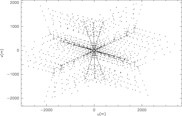
Except for the pilot study, which covered approximately an area of four square degrees around W43, we split the observations into tiles of deg in Galactic longitude and latitude. The C-configuration covers baselines between 40 and 3400 m, which results in angular resolution elements of about in the 1–2 GHz band (radio L-band, Table 2). To be more specific, the pilot study mapped approximately degrees centered on the W43 star formation complex between longitudes of 29.2 and 31.5 degrees. We mosaicked the area with 59 pointings in a hexagonal mosaic geometry sampled at spacing, corresponding to half the primary beam size at GHz. Each field was observed 4 2 min to achieve a relatively uniform uv-coverage (Fig. 2). Including overheads for flux, bandpass, and gain calibration, ten hours were needed for this part of the project, split into two observing blocks of five hours each.
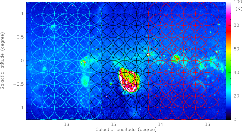
While the above approach already provided a smooth coverage, we optimized it for the rest of the survey. Considering that the primary beam changes from at 1 GHz to at 2 GHz, we used a rectangular mosaic sampling of in Galactic longitude and latitude, respectively, corresponding to half the primary beam at 1.5 GHz. Each tile of square degrees in Galactic longitude and latitude was now covered by a regularly spaced mosaic of 45 pointings. Neighboring tiles had exactly the same separation to have a uniform coverage over the full survey. Figure 1 gives an example of our mosaic pattern for three neighboring tiles where the mosaic pattern is shown for the primary beam size of at 1.5 GHz. With the varying primary beam size with frequency, the theoretical sensitivity varies slightly over the fields. However, on the one hand, this effect is very small (see also Bihr et al. 2016), and on the other hand, our noise limit is not the thermal noise, but it is dominated by the side lobe (see Sect. 4.3.4), in particular for the strong emission from the continuum and the masers. The phase 1 coverage in longitudes from 14.5 to 29.2, from 31.5 to 37.9, and from 47.1 to 51.2 degrees was covered in 20 tiles observed for five hours each. The remaining part of the survey fills the longitude gap between 37.9 and 47.1 degrees and extends from 51.2 to 67.4 degrees in additional 21 tiles. To obtain good uv-coverage, each pointing was covered three times for approximately two minutes within such a five-hour observing block, and min were needed for flux, bandpass, and gain calibration.
4.2 Calibration
The full survey was calibrated with the CASA111http://casa.nrao.edu software package. To calibrate the pilot study and phase 1 of the survey, CASA version 4.1.0 and a modified VLA pipeline version 1.2.0 were used. The second half of the survey was calibrated with slightly newer versions (CASA 4.2.2, pipeline 1.3.1), but differences between these two versions for the calibration are minimal. One major problem in L-band data analysis is the undesired man-made terrestrial signal known as radio frequency interference (RFI). While some strong RFI and bad antennas were flagged manually before the calibration, the VLA pipeline also applies automated RFI flagging on the calibrators during the calibration to improve the data quality and calibration solutions. Additional RFI flagging was applied later during the image process (see Sect. 4.3.2).
Flux, bandpass, and polarization calibration was conducted for all fields with the quasar 3C286. Two different complex gain calibrators were used: J1822-0938 for the observing blocks between 14.5 and 39.1 degrees (including the pilot study), and J1925+2106 for the remaining fields at longitudes degrees.
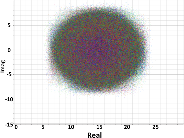
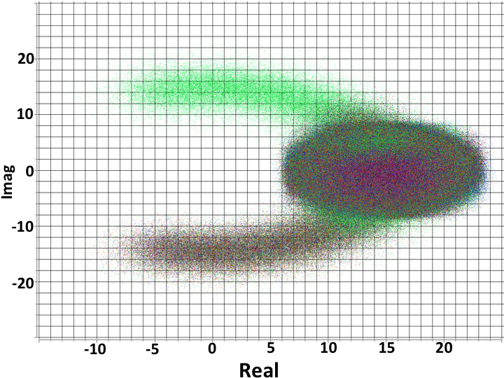
After RFI flagging of the calibrators, bandpass, flux, and gain calibration was applied using standard procedures. The absolute flux calibration uncertainty at these wavelengths is within 5%. No Hanning smoothing was performed, and the weights were not recalculated (CASA command statwt) because that sometimes affects particularly bright sources. Some modifications to the pipeline were implemented by us to improve the quality checking. The calibration was made iteratively, where after a full calibration additional quality checks and flags were applied, after which the calibration was conducted again. Figure 3 presents examples of diagnostic plots where the imaginary part of the visibility is plotted against the real part for the calibrator 3C286, which corresponds to the phase and amplitude of the visibility, respectively. For such a point source a roundish distribution is expected (Fig. 3, top panel). However, bad baselines are easily identified by strong outliers from this roundish cloud (Fig. 3, bottom panel). We typically iterated the pipeline for each tile two to three times.
4.2.1 Polarization data
The THOR polarization survey constitutes a significant step forward in terms of spectral and angular resolution over a larger bandwidth than previous Galactic plane surveys that include polarization (Condon et al., 1998; McClure-Griffiths et al., 2001; Landecker et al., 2010). The survey region connects that of the Canadian Galactic Plane Survey to that of the VLA Galactic plane survey. Compared with previous surveys, the VLA C-configuration filters out much or all of the diffuse Galactic polarized emission. THOR is only sensitive to structure on angular scales smaller than (9 pc at a distance of 10 kpc), which is well suited for more distant supernova remnants that most likely populate the narrow latitude range of the survey. Since Faraday rotation measure synthesis is performed on the ratios and , it is less sensitive to missing short spacings than for example deriving a spectral index. The main science applications of the polarization survey therefore focus on polarized extragalactic sources and Galactic supernova remnants.
Polarization calibration is performed per channel in casa after bandpass, flux, and gain calibration. Polarization angle calibration is derived from 3C286. Solutions for instrumental polarization are derived from the phase calibrator that was observed during the observing session. Even after calibration for the center of the field, instrumental polarization increases substantially with distance from the field center. Off-axis polarization calibration requires a correction to Stokes Q and U that depends on the location in the field and to first order is proportional to total intensity. Pending new holography measurements and implementation of off-axis polarization calibration in casa, our polarization calibration only applies to the field center. We intend to process the data including off-axis polarization calibration before they are released. However, experiments on bright thermal emission, for instance, on ultracompact Hii regions, indicate that leakage in our mosaics is restricted to cases with fractional polarization and very little Faraday rotation (as argued by Gießübel et al., 2013). Because of the significantly larger calibration and imaging requirements for the polarization data, even the first half of the survey is not fully reduced yet. Therefore, polarization data will be provided successively (see Sect. 4.4).
The visibility data are imaged in Stokes , , and in 2 MHz channels across the observed frequency range from 1 to 2 GHz. The restoring beam was calculated for each channel to preserve the native angular resolution. This allows us the flexibility to analyze the upper part of the frequency band separately at higher angular resolution. The lowest-frequency spectral window is noisier by a factor but is important for polarization science because it nearly doubles the coverage of the survey in space as the adjacent spectral window is lost to RFI.
4.3 Imaging
The imaging process for THOR is by far the most computationally intensive and time-consuming process of the data reduction for several reasons: (a) Large areal coverage combined with good angular resolution results in very large images with thousands of pixels in each spatial axis. The pixel sizes were adapted to the frequencies and typically had 4-5 pixels per resolution element in one dimension. (b) Thirty spectral bands (Table 1) produce an enormous bandwidth at high spectral resolution, that is, many frequency channels, which needs to be imaged one after the other. (c) The CASA software package works with high input/output rates of the data to disk and back, which is a strong constraint on the computing resources. While the raw data already comprise approximately 4 TByte, the total data volume after imaging is increased by up to a factor 10.
The computing process can be optimized by shared file systems such as the lustre system existing at the NRAO site in Socorro. Based on the requirements for THOR and future programs, we acquired a comparable computing cluster with a similar shared file system (FHGSF: Frauenhofer shared file system222http://www.beegfs.com/content/), which improves the imaging speed significantly. Nevertheless, a single spectral data cube covering km s-1 at a spectral resolution of 1.5 km s-1 for one tile ( deg) needs approximately two weeks for the imaging process. Imaging all tiles and spectral windows like this in sequence would be prohibitively time consuming. However, with the new computing system, the imaging of the data becomes feasible, although it still takes several years for the full survey, in particular because a large part has to be imaged several times due to tests and software improvements. The actual multiscale cleaning, embedded in the CASA task CLEAN, is used for imaging, and the details are described in Sect. 4.3.4.
4.3.1 Different CASA versions
All data shown are imaged with the CASA version 4.2. Although versions 4.3 to 4.6 became available during the data reduction time, we tested these versions, and for our large-scale mosaics, 4.2 resulted in the best and most reliable results. The test reference images were made with isolated sources close to the center of an individual VLA pointing without using the mosaic algorithm, but where these individual pointings were significantly offset from the phase center of a 45 pointing mosaic tile. Imaging such an individual pointing in CASA 4.2 and the following versions gave identical results, which is also expected and should be the case. Therefore, we considered the measured fluxes of these images as reliable and used them as reference values. Imaging the corresponding 45 pointing mosaic tile gave slightly varying fluxes for the same sources within 4.2 and 4.3 to 4.6. The variations within 4.2 were usually below 10%, whereas in 4.3 to 4.6 we saw systematic flux density deviations with distance from the phase center of up to 20% or more in the mosaics. The main reasons for these discrepancies are rooted in the implementation of the corrections for the primary beam response and the distance to the phase centers, which were not properly accounted for in 4.3 to 4.6 (Kumar Golap, priv. comm.). Furthermore, the primary beam correction for the continuum images was calculated in 4.3 and 4.4 for the first channel of a continuum image and for 4.2 for the central channel. Taking these variations into account, we so far consider CASA 4.2 as the most reliable version for the purpose of our large mosaic and wide-field imaging. A future data release may have the whole survey data re-imaged with a newer version of CASA as and when these problems are sorted out.
4.3.2 Radio frequency interference (RFI)
Radio frequency interference is a severe problem at the long wavelengths of this survey. While a few frequency ranges, in particular around the HI and OH lines, are protected and do not have strong RFI problems, many of the other spectral windows are strongly affected by it. In particular, two of the continuum spectral windows and seven of the recombination line spectral windows are so strongly affected by RFI that we excluded them from the analysis entirely. These windows are marked in Table 1.
Automated RFI flagging algorithms are very useful, but they also need to be used with caution. In particular for strong narrow spectral lines, for example, the OH masers, RFI flagging algorithms are prone to also flag the maser peaks. Hence, for the HI and OH spectral windows we refrained from directly applying automated RFI flagging algorithms. Since these windows are protected anyway, however, it was not a severe problem, and individual checks and some sparse flagging by hand accounted for most of the RFI in these bands.
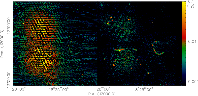
For the continuum bands, the spectral windows cont4 and cont7 around 1.4 and 1.7 GHz are of the best quality. The spectral window cont4 around the HI line has hardly any RFI and requires little or no RFI flagging. The window cont7 around 1.8 GHz still is of good quality, and only a few individual RFI checks and flagging accounted for most of the RFI features there. All other continuum spectral windows were more strongly affected by RFI. Since this RFI contamination varies in frequency, sky position, and time, manual flagging is not feasible for this large survey. We therefore explored the RFlag algorithm within CASA that was first introduced to AIPS by E. Greisen in 2011. This iterative algorithm considers the statistics in both time and spectral domain. Outliers are identified by considering each individual spectral channel for the whole duration of an observation of a target, and also by considering all spectral channels for each integration time step, and the flagging of outliers is made iteratively (see CASA manual333http://casa.nrao.edu/docs/cookbook/index.html for more details). As mentioned above, strong spectral features such as masers would be considered outliers and thus flagged during that procedure. Therefore, the RFlag algorithm cannot be applied to the HI and OH spectral windows. However, since the continuum emission should not show such variations over the bandpass, it can be applied to those windows. Furthermore, the radio recombination lines are typically extremely weak and can often only be reliably identified after stacking several lines (see description below). Hence, the RFlag algorithm can also be applied on weak features such as the RRLs. Testing the performance of RFlag showed that using the default thresholds ( rms in time and frequency domain) reliably removes most of the RFI in the respective windows (most, but not all, see Fig. 4 for possible residuals). Bands like cont2 around 1.2 GHz have so much RFI over the whole bandpass that no usable data remain, hence the algorithm does not give reasonable results in such extreme cases. However, for the non-marked spectral windows shown in Table 1, the RFlag results greatly improved the data quality. Figure 4 shows one example region where the RFI was largely removed by applying the RFlag algorithm once with these default values.
We performed several tests with the RFlag algorithm to further quantify its effects. We imaged a dataset in the RFI-free cont4 band around the HI line with and without applying the RFlag algorithm. Measuring the noise in both images, it is almost identical, indicating that the RFlag algorithm did not flag significant good data. Extracting the flux densities using these two approaches, we find no significant deviations over the full range of flux densities for unresolved and small sources (smaller than ). For more details and corresponding figures, see the continuum catalog paper by Bihr et al. (2016). The RFI removal effects for larger-scale structures are discussed in the following subsection.
4.3.3 Spatial filtering for extended sources
Extended sources suffer from spatial filtering effects for several reasons. While the observations clearly filter out emission because of the missing short baselines, RFI removal also lowers flux density measurements of extended sources.
Within a full 12-hour track, the VLA can observe spatial scales up to 970′′ in L-band and C-configuration. However, with the shorter integrations of 6 min per mosaic pointing, flux density on smaller scales is also filtered out. To investigate the spatial filtering in our setup, we simulated observations with Gaussian intensity profiles of varying sizes, employing our given uv-coverage. We find that sources with sizes up to are reasonably well recovered, with flux density losses of less than 20%. The use of the multiscale algorithm (see also next section) within CASA was very important for recovering the flux density. Since the filtering also depends on frequency, spectral indices are not reliable for structures larger than . Nevertheless, the spectral indices for smaller structures remain trustworthy (see also Bihr et al. 2016).
The additional spatial filtering due to the RFI flagging is also based on the fact that extended sources show high amplitudes and amplitude gradients at small uv-distances. Since the RFlag algorithm flags outliers in the time and frequency domain, some of these high values may also be considered as outliers and hence be flagged. Similar to the RFI tests outlined in the previous selection, we again applied the RFlag algorithm to the cont4 spectral window around the HI line that is practically RFI free. As shown in Bihr et al. (2016), for uv-distances smaller than 300, this flagging starts to significantly affect the flux densities, and more than of the data may be flagged. Following the simple estimate of the corresponding spatial scale with the angular scale and the baseline length, corresponds to scales of . For structures on scales between to , the flux density removal due to RFlag is only on the order of . Hence, while for small spatial scales the flux density uncertainties because of spatial filtering are negligible, they have to be considered more seriously for the large-scale structures.
In summary, while automated RFI removal does affect the flux density on larger scales, the spatial filtering is dominated by the normal filtering of the interferometer arising from the missing short spacings.
4.3.4 Additional imaging effects and procedures
In addition to the imaging procedures and effects outlined above, a few more important steps are also described below.
Multiscale cleaning:
The clean algorithm in its standard form identifies peak emission features and hence better recovers smaller point-like emission. Although it is possible to recover some larger-scale emission by adding many point-like components, it nevertheless is not ideally suited for extended emission. The CASA package provides a multiscale version of this procedure (Rau & Cornwell, 2011). As the name suggests, it does not look only for point-like components, but also considers larger spatial scales. The CASA setup allows us to select different spatial scales to focus on, and we experimented with many of them using mock input images. After extended testing, the default values for the multiscale clean task were used. In this setup, the algorithm focuses on recovering three main spatial scales: point-sources, the synthesized beam size, and three times the synthesized beam size. This setup enables us to recover the large-scale emission best. Therefore, we used this setup during the imaging process. We cleaned the data using a robust value in the clean-task of CASA of 0.5. The positional uncertainties for the final images are within (Bihr et al., 2016).
Combination with VGPS data:
The THOR survey was initially set up to be directly combined with the HI and 1.4 GHz continuum data from the VGPS survey (Stil et al., 2006). This survey observed the HI line with a spectral coverage of effectively MHz (or 341 km s-1), and the line-free part of this spectrum was used for the continuum image. VGPS combined VLA D-configuration configuration data with single-dish observations from the GBT and Effelsberg. The angular resolution of their final data product is , and because of the combination of VLA with GBT, the large-scale emission is recovered. These data are used by THOR to complement the short spacing information for the HI and the 1.4 GHz continuum emission. While this works very well for the HI data because both data are on the same spectral grid, we recall that for the continuum totally different widths of the spectral bands are used ( MHz versus MHz). Therefore, while the spatial structure of the combined 1.4 GHz continuum image is reliable, the absolute fluxes need be considered with caution. We therefore used the THOR-only data to determine our spectral index (Bihr et al., 2016).
The THOR and VGPS data can be combined in two different ways. Either the VGPS data are used as an input model in the deconvolution of the THOR data, or the THOR data are independently imaged andare afterwards combined with the feather task in CASA. We compared these two approaches, and while using VGPS as an input model gave good results for the 1.4 GHz continuum data, this approach reduced the signal-to-noise ratio for the HI data. Therefore, for the latter we first imaged the THOR HI data separately and then feathered them with the VGPS data.
Recombination line imaging and stacking:
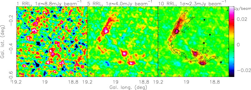
The treatment of the radio recombination lines (RRLs) of this survey is unique because each individual line is too weak to be detected in most regions. However, because of the power of the new VLA correlator, we were able to observe 19 of them simultaneously. While some of the spectral windows are RFI contaminated (see Table 1), typically about 12 spectral windows were usable. Because of the weak emission in each individual RRL, cleaning the data was not appropriate. For the RRLs we therefore Fourier transformed the data and afterward worked with the dirty images. All spectral lines were imaged with exactly the same velocity resolution of 10 km s-1. After smoothing all RRL images to the same angular resolution (, corresponds approximately to the poorest resolution achieved at the longest wavelength), we then stacked the images with equal weights in the velocity domain to improve the signal-to-noise ratio of the final RRL images. After this stacking process, the averaged RRL emission could be recovered in a significant number of regions in the survey (Sect. 5.4). Figure 5 presents in an example toward the Hii region G18.9-0.3 how the stacking process improves the noise and thereby the signal-to-noise ratio. Measuring the rms in a single 10 km s-1 channel results in values of 8.8, 4.0, and 2.3 mJy beam-1 for the 1, 5, and 10 stacks of this example region, respectively.
Although the native spectral resolution for most parts of the survey is better than 5 km s-1, to image such a large number of datasets in a uniform manner and to achieve an unbiased census of RRL detections, we are currently using the data at a spectral resolution of 10 km s-1. However, considering that the thermal line-width of ionized gas at 10000 K is 15 km s-1 and typically measured line-widths of recombinations lines in Hii regions between 20 and 25 km s-1 (Anderson et al., 2011), this is still reasonable.
Angular resolution and rms noise:
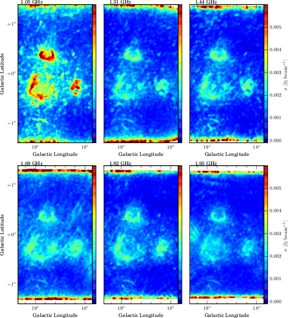
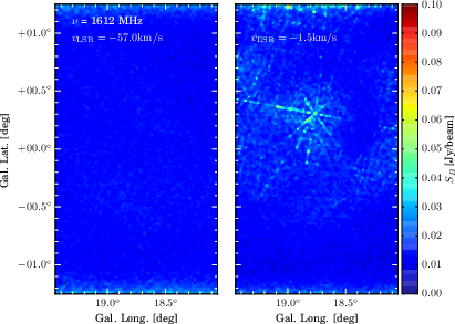
The final angular resolution elements and the rms noise levels vary between the different lines and continuum bands, but also from the lower to the upper end of the bandpass and from the low- to the high-longitude range. Table 2 summarizes the main angular resolution and mean noise parameters of THOR. While in emission-free regions we almost reach the thermal noise, our maps are mostly dominated by side-lobe noise. This means that the noise levels vary throughout the fields. This behavior is particularly strong in the continuum emission and around the strong OH maser. The side-lobe noise is a direct reflection of the uv-coverage and the corresponding dirty beam. For a very uniform uv-coverage, the dirty beam is almost Gaussian and side-lobe noise is weak. However, for less uniform uv-coverage, the dirty beam has stronger negative features that remain difficult to clean. As described in Sect. 4.1 and shown in Fig. 2, to conduct such a large survey, the uv-coverage of each individual pointing does not fill the uv-plane well. This directly results in a less perfect dirty beam and thereby higher side-lobe noise as observed here. This effect also depends on the strength of the sources and is therefore particularly prominent for the strong masers and the strongest continuum sources. For the other parts of the survey, side-lobe noise is less severe and can almost be neglected.
Bihr et al. (2016) analyzed the noise behavior of the continuum data in the first half of the survey in depth, and found that 50% of the survey area have a noise level below a 7 level of 3 mJy beam-1. Above their chosen 7 threshold 95% of all artificially injected sources are detectable. Only 10% of the area has a noise level above a 7 value of 8 mJy beam-1. For comparison, Walsh et al. (2016) analyzed the completeness of the OH maser data in the pilot field around W43, and found that almost all OH data are complete at 0.25 Jy beam-1, and that 50% are complete at a level of 0.17 Jy beam-1.
The side-lobe noise is less of a problem for the HI because these data are complemented by VGPS D-configuration and GBT data, which significantly improves the image quality. Nevertheless, side-lobe noise has also to be taken into account for the HI data toward strong continuum sources. Since the recombination lines are very weak, they also do not suffer much from side-lobe noise compared to these lines and the continuum. Furthermore, as outlined in the previous paragraph, the signal-to-noise ratio increases because of the stacking. In total, the rms for the recombination lines is much more uniform and represented well by the value shown in Table 2.
In the appendix (Sect. A) we show representative noise maps for the continuum, HI, and OH for a selected tile of the survey to visualize the noise spread.
| Band | rms | data productsb | |
|---|---|---|---|
| HI | to | 12c | THOR only with & without cont., THOR merged with VGPS continuum-subtracted |
| OH1 | to | 10d | continuum-subtracted, native resolution and smoothed |
| OH2/3 | to | 10d | continuum-subtracted, native resolution and smoothed |
| OH4 | to | 10d | continuum-subtracted, native resolution and smoothed |
| cont1 | to | 1.1e | native resolution and smoothed |
| cont3 | to | 0.7e | native resolution and smoothed |
| cont4 | to | 0.6e | native resolution and smoothed |
| cont6 | to | 0.6e | native resolution and smoothed |
| cont7 | to | 0.5e | native resolution and smoothed |
| cont8 | to | 0.7e | native resolution and smoothed |
| H | 3f | stacked images with 10 km s-1 and resolution | |
| for all products also calibrated visibilities |
a This data release 1 contains the data of the first half of the survey. The remaining data will follow after the ongoing calibration and imaging process.
b The synthesized beams depend on Galactic longitude.
c rms per channel after smoothing to a uniform beam of .
d rms per channel after smoothing to a uniform beam of .
e This is the rms in a emission-free region. Considering side-lobe noise, 90% of the whole coverage is below 1.6 mJy beam-1 (Bihr et al., 2016).
f After smoothing to in 10 km s-1 channels of stacked maps.
4.4 Data products and data access
The data are provided to the community as calibrated images. While the continuum data for each band (Table 2) are accessible as individual single-plane fits-files, the spectral line data are provided as fits data-cubes. These data cubes always cover the whole velocity range of Galactic emission in the respective part of the Milky Way. To stay within reasonable file-size limits, the data can be downloaded in tiles of approximately 2.5 square degrees each. We provide the data with different angular resolution and with and without continuum-subtraction. More details can be found in Table 2. Currently, only full tiles can be downloaded, but we plan also smaller cutout-image options. The current data release 1 contains the data of the first half of the survey, the second half will follow after the ongoing data processing has been completed. Because of the significantly larger data calibration and imaging requirements for the polarization, which is not completed yet (Sect. 4.2.1), the polarization data will also be provided at a later stage. The data can be accessed at the project web-page http://www.mpia.de/thor.
5 Initial results
5.1 Continuum emission
THOR provides a variety of continuum data products. We have the full spectral coverage from 1 to 2 GHz, which enables us to derive spectral indices for all identified regions. These spectral indices are a very useful tool for differentiating the physical properties of the regions, for instance, for resolving extragalactic synchrotron emission from Galactic Hii regions. For the first half (phase 1) part of THOR, a detailed presentation of the continuum source catalog and early results can by found in Bihr et al. (2016), and we refer to that paper for more details.
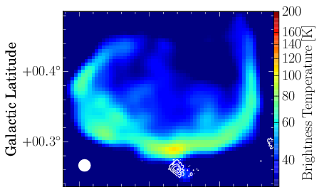
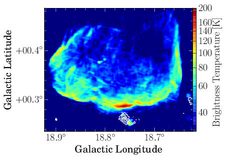
In contrast to the other continuum bands that are only observed with THOR in the C-configuration, for spectral window cont4 we also have the complementary VGPS data from the VLA in D-configuration and the Effelsberg observations. Although the absolute flux density should be considered with caution in the combined dataset (Sect. 4.3.4), this THOR+VGPS 1.4 GHz continuum dataset gives a unique view of our Milky Way. It resolves the small-scale structure with the THOR data and at the same time recovers large-scale structure from the VGPS survey. Figure 6 shows a zoom into one region (the supernova remnant G18.8+0.3) where the direct comparison between the previous VGPS data at resolution and our new THOR data at resolution is presented. The improvement in angular resolution and dynamic range is striking. For example, while the low-resolution VGPS image does not reveal a cm counterpart to the cold 870 m dust emission at the southern tip of the supernova remnant, the new THOR image clearly reveals an embedded Hii region within the ATLASGAL dust core. Since this source is at the tip of the supernova remnant, it may suggest triggered star formation. This is only an example for the direction in which the new high-quality data can lead the research.
Figures 7 and 8 present these combined images. Below 17.5 deg longitude, the VLA D-configuration data do not exist, and we were only able to combine the new THOR data with the complementary GBT single-dish observations. This resulted in less structural information in that region and in more side-lobe noise, in particular around the Hii region M17 at 15 deg longitude.
The 1.4 GHz continuum images exhibit a multitude of features. Close to the Galactic mid-plane, the emission is dominated by Galactic and often extended structures. Most of these are either Hii regions or supernova remnants. Comparing these structures with Galactic Hii regions identified in the mid-infrared by Anderson et al. (2014, 2015), we mostly find good matches between the radio and mid-infrared identified regions. The combined VGPS and THOR 1.4 GHz data recovers emission from both extended and compact sources. Close to the Galactic mid-plane, most of the emission is from Galactic Hii regions (cataloged by Anderson et al. 2015), but there is also emission from known supernova remnants (SNRs). From visual inspection, we find that nearly all known Hii regions and SNR are detected in these data.
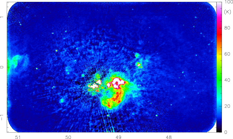
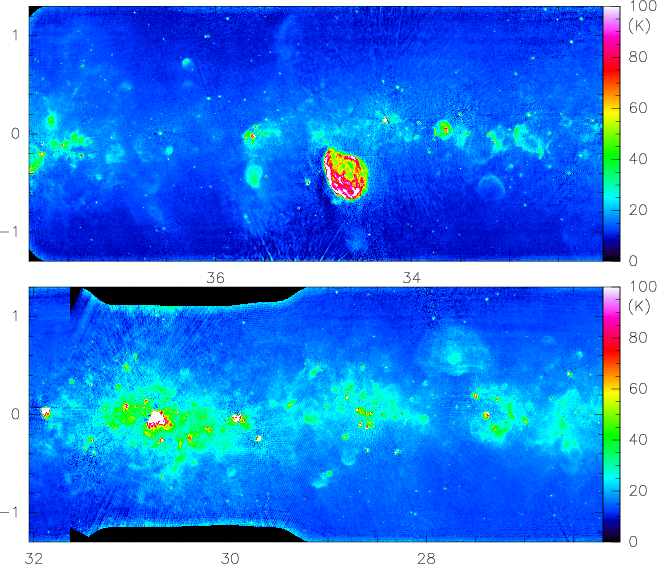
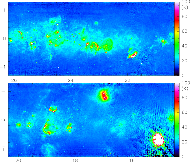
Furthermore, the THOR+VGPS data have revealed a new Hii region and SNR candidates. Using WISE mid-infrared data, Anderson et al. (2015) identified over 700 Hii region candidates that lacked radio continuum emission in previous surveys over the area now covered by THOR data release 1 (Fig. 7). Hii regions should all have coincident radio continuum and mid-infrared emission (e.g., Haslam & Osborne 1987). By visual inspection of the THOR data, we found that 76 of these previous radio-quiet candidates do indeed have faint radio continuum emission in the THOR+VGPS data, and a further 52 have emission in at least one of the individual THOR continuum sub-bands. These are therefore probably genuine Hii regions. The radio continuum sensitivity of THOR+VGPS is sufficient to detect Hii region emission from single B1 stars to a distance of 20 kpc, and these data can therefore help to complete the census of Galactic Hii regions over the survey area. In addition to the new Hii region detections, we have identified over 50 SNR candidates in the THOR+VGPS data, and are working to further characterize the nature of these sources. The spectral index helps to distinguish between Hii regions, which reveal a flat or positive spectral index and SNRs, which typically reveal a spectral index around -0.5 (e.g., Green 2014; Dubner & Giacani 2015, but see also Bhatnagar et al. 2011 for other spectral indices in SNRs). Bihr et al. (2016) used the spectral index information to confirm four SNR candidates proposed by Helfand et al. (2006), which exhibit these typical spectral indices.
In addition to these extended sources, the continuum images show many point sources. These are easy to identify at higher Galactic latitudes because they are less easily confused with Galactic sources, but we also find many point sources close to the Galactic plane. Most of these point sources are of extragalactic origin and can often be identified by a negative spectral index. Bihr et al. (2016) conducted a detailed analysis of the continuum emission in the first half of the THOR survey, and they identified 4400 sources of which 1200 are spatially resolved. For 1800 sources they were able to derive spectral indices with a distribution peaking at values around -1 and 0. These correspond to steep declining sources mostly of extragalactic origin, whereas the flat-spectrum sources are largely Hii regions.
5.2 Atomic hydrogen
The atomic hydrogen data can be used in different ways. On the one hand, we have the THOR-only C-configuration HI observations, which do not recover the large-scale emission. They are, however, ideally suited to measure the absorption profiles at high angular resolution against Galactic and extragalactic background sources. With these absorption spectra, we can derive the HI optical depth and from that the HI column density with high accuracy for several hundred lines of sight in our Milky Way. Examples for these absorption spectra can be found in the pilot study paper about the W43 complex (Bihr et al., 2015). These HI absorption spectra can also be set into context with the corresponding OH absorption spectra discussed in Sect. 5.3. While these optical depth measurements are important for individual regions, it will also be interesting to interpolate between these individual data points to create an optical depth map of the Milky Way. Furthermore, the HI absorption data are important to distinguish the near- and far-distance ambiguities for kinematic distances within the Milky Way (e.g., Ellsworth-Bowers et al. 2015).
The combined THOR+VGPS HI data allow us to also recover the large-scale emission. However, we recall that the surface brightness sensitivity in Kelvin gets worse with increasing angular resolution. For the combined THOR+VGPS data, the brightness sensitivity for a spectral resolution of 1.6 km s-1 at , , and is 16, 3.9, and 1.8 K, respectively. At resolution, the corresponding rms of the VGPS alone is even slightly superior at 1.5 K. When only the large-scale structure is of interest, the VGPS HI data may still be used, but as soon as higher angular resolution is needed, the power of the THOR survey can be exploited.
The combined THOR+VGPS data will be also useful in probing intensity fluctuation of the spectrally resolved HI signal from angular power spectra over the angular scale range of for different parts of the Galactic plane (e.g., Liszt et al. 1993; Elmegreen & Scalo 2004; Roy et al. 2010). For some of the directions where the distance-velocity mapping is uniquely known from the Galactic dynamics, the data cube can also be used to derive the three-dimensional power spectrum to quantify the structures of atomic ISM.
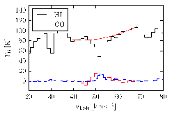
One particularly interesting aspect of the HI emission is the identification and study of cold HI often seen as HI self absorption or HISA (e.g., Gibson et al. 2005a, b). When features are more narrow than those of molecular lines (e.g., OH, C18O, 13CO), this absorption is referred to as HI narrow self-absorption (HINSA, Li & Goldsmith 2003). While the total HI emission is always a mixture of the cold and warm neutral medium, these HISA features are dominated by the cold HI component of the ISM. This cold HI is therefore thought to be closely related to the molecular gas during the formation of molecular clouds. One of the goals of THOR accordingly is to systematically study the HISA properties and set them into context with the even denser portions of molecular clouds visible in CO or dust continuum emission. HISA features enables us to not only study the cold HI column density, but also to investigate the kinematic properties of the HI in comparison to the molecular gas measured in CO. Figure 9 shows an example of a HISA spectrum in comparison with the molecular component. A detailed study of one large-scale HISA is also presented in Bihr et al. (in prep.).
5.3 OH maser and thermal components
The OH part of THOR also covers two very different aspects. This is the first unbiased northern hemisphere survey of OH masers in all four OH transitions at 1612, 1665, 1667, and 1720 MHz. While some surveys at lower sensitivity and mainly focusing on the 1612 MHz maser exist (e.g., Sevenster et al. 2001), here we can for the first time compare the maser properties of the different lines in a statistical sense. OH masers are known to trace different astrophysical entities. The 1612 OH maser is often associated with evolved stars, for example (e.g., Sevenster et al. 2001), the 1665 and 1667 masers tend to be more prominent toward star formation regions (e.g., Reid & Moran 1981; Elitzur 1992), and the 1720 maser is also found toward supernova remnants (e.g., Elitzur 1976; Wardle & Yusef-Zadeh 2002). However, none of these associations is exclusive, and it is also possible to find all four transitions toward the same target region (e.g., Caswell et al. 2013; Walsh et al. 2016).
A detailed description and statistical analysis of the OH maser properties toward the four square-degrees pilot region around W43 has been presented by Walsh et al. (2016). The identification of 103 maser sites in that area covering all four maser species outlines the great potential of the full survey. In this pilot region, we identified 72 sites of 1612 MHz maser emissions, 64% of which are associated with evolved stars, 13% associated with star formation, and 24% are of unidentified origin. The 11 maser sites that emit in the two main lines at 1665 and 1667 MHz are all located within star-forming regions. Of the 11 sites with only 1665 MHz maser emission, 8 are associated with star formation and three are of unknown origin. It is interesting to note that out of the four 1720 MHz masers, which are commonly believed to arise in supernova remnants, three in our field are associated with star formation and the fourth is again of unknown origin. For more details we refer to Walsh et al. (2016). The analysis of the remaining part of the survey is currently being carried out (Walsh et al. in prep.)
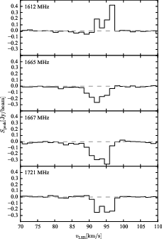
In addition to the maser emission, THOR is also sensitive to the OH absorption toward strong continuum sources such as Hii regions. These absorption lines are usually of thermal origin and allow us to study the molecular components of the ISM along the same lines of sight as the HI absorption lines discussed in Sect. 5.2. Figure 10 presents an example of OH absorption lines toward a bright background continuum source, classified as an ultracompact Hii region in the CORNISH survey catalog (Hoare et al., 2012; Purcell et al., 2013). The two main lines (at 1665 and 1667 MHz) and the 1720 MHz satellite line are found in absorption, while the OH 1612 MHz satellite transition is seen in emission. Such inversion can occur because of radiative maser processes (e.g., Elitzur 1992). The full analysis of the OH absorption lines, setting them into context with HI absorption spectra, HISA features, and CO emission lines, will be presented in Rugel et al. (in prep.).
While most of the absorption spectra are spatially unresolved, we can also spatially resolve the absorption lines against strong and extended Hii regions toward a few particularly strong regions, for example, W43, W51 or M17 (e.g., Walsh et al. 2016, Rugel et al. in prep.). However, for most other parts of the THOR survey, the OH absorption is mostly very compact. We do not have the corresponding more D-configuration data (as for the HI or 1.4 GHz continuum emission), which are sensitive to the more extended structures, therefore we detect hardly any thermal OH emission. However, we are exploring whether combining these data with single-dish observations (from Effelsberg and/or Parkes) will give useful information for studying the emission of OH on larger scales.
5.4 Radio recombination lines
As outlined in Sect. 4.3.4, for most parts of the survey, individual RRLs are barely detected, but after stacking all non-RFI-affected recombination line images in the velocity domain, we can identify the ionized gas spectral line emission toward a significant number of sources (28 regions in the first half of the survey by visual inspection of the data alone).
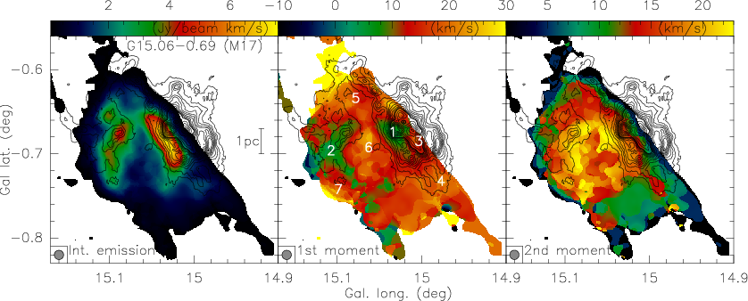
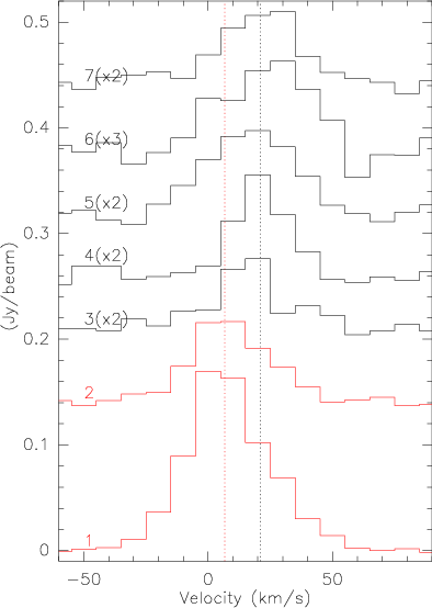
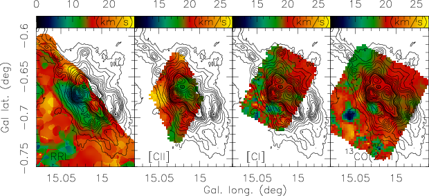
To outline the potential of these data, we present a more detailed look at the data corresponding to the famous Hii region M17 (or G15.06-0.69 in our Galactic nomenclature). Figure 11 shows the zeroth-, first-, and second-moment maps (integrated emission, and intensity-weighted peak-velocities and line widths) toward the M17 Hii region. While the integrated zeroth-moment map clearly shows the main shell-like Hii region surrounding the central OB cluster (e.g., Hanson et al. 1997; Hoffmeister et al. 2008), the interesting aspect of the RRLs is that we can also study the kinematics of the ionized gas and set it into context with other components of the ISM. The right panel of Fig. 11 shows the line-width distribution, and the broadest lines are found toward the strongest emission features of the Hii region. In addition to this, Fig. 11 (middle panel) clearly shows that the main arc-like emission of the Hii region is associated with gas peaking around 5 km s-1 , while all the surrounding ionized gas is shifted to higher velocities around 20 km s-1. This shift in peak velocities is also seen in the individual spectra extracted toward several positions and shown in Fig. 12.
The question now arises whether such a velocity shift is only seen in the ionized gas between the main western emission feature of the Hii and the environment, or if a similar shift of velocities is also found in other phases of the ISM. To investigate this in more detail, Fig. 13 presents the peak velocity maps of [CII] tracing the weakly ionized gas and the atomic and molecular carbon components observed in [CI] and 13CO(2–1) (data from Pérez-Beaupuits et al. 2012, 2015). The peak velocities of the molecular and atomic components are both centered on 20 km s-1, and the weakly ionized [CII] is found between 15 and 20 km s-1. Similar velocity shifts are also found in HI absorption line studies by Brogan et al. (1999) and Brogan & Troland (2001). All environmental gas components therefore exhibit velocities shifted by 10 to 15 km s-1 relative to the main velocity found toward the Hii region ridge. Pellegrini et al. (2007) modeled the M17 Hii region as being in pressure balance between the radiative and wind components induced by the central cluster (Hanson et al., 1997; Hoffmeister et al., 2008) and magnetic pressure within the environmental cloud. While clumpiness also comes into play (e.g., Stutzki et al. 1988), most features presented here and in the literature can be reproduced by such a model (e.g., Pellegrini et al. 2007).
While individual lines of sight in recombination lines were reported in the literature from interferometric (e.g., Pellegrini et al. 2007) and single-dish data (e.g., Anderson et al. 2011, 2015), full mapping of RRL emission over large samples has been rare (e.g., Urquhart et al. 2004). This is partly caused by the often very weak recombination line emission and hence inadequate sensitivity. In this context, THOR now provides an entirely new set of spectrally and spatially resolved recombination line data toward a large sample of Hii regions because the stacking approach enables us to reach higher sensitivities than usually possible when observing only single lines.
Here, we present the data at uniform spatial and spectral resolution, but in the future, we are planning to re-image individual bright and compact regions with strong signal at higher spectral resolution. Regions where the sensitivity for individual lines is adequate can then also be imaged at higher angular resolution in those individual lines.
5.5 Polarization and Faraday rotation measures
Since the polarization calibration and data analysis is far more complicated than for the rest of the data, we have so far only worked on the data of the pilot region. The full survey will be presented and analyzed in a separate paper. Here, we outline the potential of the survey and highlight initial results toward the pilot region. The main data products of the THOR polarization survey will be a catalog of linearly polarized emission and image cubes of Stokes , , and . The catalog will be made by applying Faraday rotation measure synthesis (Brentjens & de Bruyn, 2005). It will list fractional polarization and polarization angle at up to three reference frequencies across the band, and one or more measurements of the Faraday depth , defined through the line-of-sight integral
where is measured in rad m-2, the electron density along the line of sight in cm-3, the component of the magnetic field projected on the line of sight, in G, and the line-of-sight distance in pc (e.g., Brentjens & de Bruyn 2005). A single line of sight can have more than one Faraday depth depending on the location of different synchrotron-emitting regions embedded in the Faraday rotating plasma. The angular resolution of THOR at the lowest frequency (1 pc at a distance of 10 kpc) reduces confusion of regions with different Faraday depth inside the synthesized beam, but true line-of-sight pile-up of emission with different Faraday depths is always a possibility (Brentjens & de Bruyn, 2005).
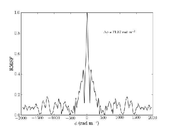
Figure 14 shows the rotation measure spread function (RMSF) for the supernova remnant Kes75 in the pilot region. This is the equivalent of a point spread function in Faraday depth space. The theoretical resolution in Faraday depth for the THOR survey, following Brentjens & de Bruyn (2005), is 60 rad m-2. In practice, rejection of channels affected by RFI across the band reduces the resolution somewhat to rad m-2. More importantly, the loss of two spectral windows to RFI causes significant broad side lobes at 300 rad m-2 that can interfere with the detection of faint components. The highest Faraday depth that can be detected by THOR before Faraday rotation across a single frequency channel depolarizes the emission is (Brentjens & de Bruyn, 2005). The Faraday depth resolution of THOR opens a new part of parameter space in terms of exploring structure in Faraday depth and its ability to detect very large Faraday depths.
The widest continuous range in Faraday depth that can be recognized in THOR is given by the shortest wavelength covered (Brentjens & de Bruyn, 2005). The simplest form of a continuous Faraday depth structure is a region filled with plasma that also emits synchrotron emission everywhere along the line of sight. Depending on the shortest wavelength observed, there is a largest Faraday depth scale that can be recognized, similar to the missing short spacing problem in radio interferometry. For THOR, the largest extent in Faraday depth is 133 rad m-2, yielding a dynamic range for Faraday depth structure of a factor . To set this into perspective, a region with a size of pc, cm-3, G and would produce detectable Faraday complexity in THOR. There are many different permutations of line of sight depth, electron density, and magnetic field strength that can produce resolved structure in Faraday depth.
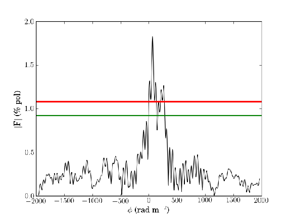
Figure 15 demonstrates how these numbers combine for the SNR Kes 75. This figure shows the result of Faraday rotation measure synthesis using Stokes and spectra integrated over the pulsar wind nebula. After division by Stokes , the amplitude of the Faraday depth spectrum is expressed as a percentage of the total flux density. We define the detection statistics by repeating the analysis 300 times with the Stokes and replaced with equivalent spectra extracted from empty regions in the image. The highest noise peak is used in Fig. 15 as the detection threshold for the on-source Faraday depth spectrum. We also apply a lower limit of 1% for detected polarized emission to avoid false detections related to residual instrumental polarization.
We find two peaks that exceed the 1-in-300 detection threshold. The peaks are separated by 200 rad m-2, which is well beyond the Faraday depth resolution of the data. This is a very broad Faraday depth range for the angular scale . The separation between the peaks is more than the largest Faraday depth scale that can be observed in THOR. We can therefore not exclude an additional broad component with a Faraday depth scale comparable to the separation of the peaks. Repeating the analysis by separating the band in thirds by indicates a gradual decrease in fractional polarization from 3.3% at the upper frequency range to 1.5% at the center, and no formal detection in the lowest frequency spectral window. The THOR polarization catalog will produce this level of information for all detected sources. By contrast, different regions of the bright shell of Kes 75 only show peaks at Faraday depths near 0 with amplitudes that are consistent with residual polarization leakage.
THOR will provide polarized background sources for studies of the Galactic magnetic field on scales spanning four orders of magnitude, as well as measurements of Faraday depth structure for individual objects in the Milky Way. The angular resolution and polarization information will make this survey ideal for magnetic field structure and depolarization in supernova remnants, and for the detection of young supernova remnants embedded in crowded star formation regions.
6 Discussion
Based on the early results presented in the previous section, we envision a multitude of future scientific applications. The advantage of THOR is that we do not have to rely on single case studies but that larger statistical approaches are possible. For example, the HI study of the W43 cloud presented in Bihr et al. (2015) will be extended to many clouds within the Milky Way. Similarly, feedback studies as indicated by the M17 data in Sect. 5.4 will be extended to the whole sample of detected Hii region in the radio recombination line emission. In a different application, the HI data enable studying the density fluctuation structure function of the CNM down to a few tens of arcsec scales. This structure function is related to the ISM turbulence and can be directly compared to different theoretical models to constrain turbulence and energy dissipation mechanisms (e.g., Dickey et al. 2001; Audit & Hennebelle 2010).
For OH masers and absorption studies, THOR provides the perfect dataset. However, for thermal OH emission, the extended structures are filtered out by our C-configuration observations. We are currently exploring whether complementing the THOR OH data with short spacing from the SPLASH survey (Dawson et al., 2014) or complementary Effelsberg/GBT observations is sufficient, or if the shorter baselines from the VLA in D-configuration are needed for such an aspect of the ISM studies. Similarly, the continuum data allow us to derive spectral indices for compact structures (Bihr et al., 2016), but spectral indices for more extended sources such as SNRs are much harder to determine from THOR data alone. Therefore, we are currently examining whether single-dish short spacings are sufficient for the science goals related to the continuum emission in the survey, or if D-configuration data may be needed.
We currently merely scratch the surface of the polarization aspect of the THOR survey. Since we have observed the full polarization, Faraday rotation and magnetic field studies of the Milky Way will be feasible. However, the data calibration, imaging, and analysis aspect of this part of the survey have yet to be realized, and therefore, polarization and magnetic field studies will be presented in forthcoming publications (e.g., Stil et al. in prep.).
In addition to the THOR data as a stand-alone survey, it will obviously be important to combine THOR with existing surveys at other wavelengths. Only then we will be able to address all facets of the Milky Way in its appropriate depth. Understanding Galactically important regions such as the bar–spiral arm interface can directly be compared with extragalactic studies (e.g., THINGS, Walter et al. 2008) and thus be set into a global context. The combination of Galactic and extragalactic systems allows us to derive a concise and complete picture of the ISM and star formation processes.
Furthermore, THOR can also be considered as a precursor of Square Kilometer Array (SKA) pathfinder science because the planed GASKAP survey (The Galactic ASKAP survey) with the Australian SKA Pathfinder telescope will achieve comparable sensitivities and angular resolution elements in the southern hemisphere (Dickey et al., 2013).
7 Summary
We presented the survey specifications, scientific goals, and early results of the new Galactic plane survey THOR: The HI/OH/Recombination line survey of the Milky Way. We release the data stepwise, including the first half of the data in this paper. The remaining data will be provided successively after the ongoing calibration/imaging process. The data can be accessed at the project web-page at http://www.mpia.de/thor.
THOR observes the spectral lines of HI, OH, and several radio recombination lines as well as the continuum emission from 1 to 2 GHz in full polarization over approximately 132 square degrees between Galactic longitudes of 14.5 and 67.4 deg and latitudes deg. These data allow us to study the different phases of the ISM from the atomic HI to the molecular OH and the ionized gas in the recombination and continuum emission. This enables studies of the atomic to molecular gas conversion, molecular cloud formation, feedback processes from the forming Hii regions, and magnetic field studies of the ISM. We showed selected results from these datasets. In addition to using THOR by itself, it will also be useful in conjunction with many other existing Galactic plane surveys to study the interplay of the various components of our Milky Way.
Acknowledgements.
The National Radio Astronomy Observatory is a facility of the National Science Foundation operated under cooperative agreement by Associated Universities, Inc. We like to thank Juan Pablo Perez-Beaupuits for providing the ionized, atomic, and molecular data of M17 presented in Fig. 13.References
- Abreu-Vicente et al. (2016) Abreu-Vicente, J., Ragan, S., Kainulainen, J., et al. 2016, ArXiv e-prints
- Anderson et al. (2015) Anderson, L. D., Armentrout, W. P., Johnstone, B. M., et al. 2015, ApJS, 221, 26
- Anderson & Bania (2009) Anderson, L. D. & Bania, T. M. 2009, ApJ, 690, 706
- Anderson et al. (2014) Anderson, L. D., Bania, T. M., Balser, D. S., et al. 2014, ApJS, 212, 1
- Anderson et al. (2011) Anderson, L. D., Bania, T. M., Balser, D. S., & Rood, R. T. 2011, ApJS, 194, 32
- Audit & Hennebelle (2010) Audit, E. & Hennebelle, P. 2010, A&A, 511, A76
- Ballesteros-Paredes et al. (1999) Ballesteros-Paredes, J., Hartmann, L., & Vázquez-Semadeni, E. 1999, ApJ, 527, 285
- Ballesteros-Paredes et al. (2011) Ballesteros-Paredes, J., Vázquez-Semadeni, E., Gazol, A., et al. 2011, MNRAS, 416, 1436
- Banerjee et al. (2009) Banerjee, R., Vázquez-Semadeni, E., Hennebelle, P., & Klessen, R. S. 2009, MNRAS, 398, 1082
- Bertram et al. (2016) Bertram, E., Glover, S. C. O., Clark, P. C., Ragan, S. E., & Klessen, R. S. 2016, MNRAS, 455, 3763
- Beuther et al. (2012) Beuther, H., Tackenberg, J., Linz, H., et al. 2012, ApJ, 747, 43
- Bhatnagar et al. (2011) Bhatnagar, S., Rau, U., Green, D. A., & Rupen, M. P. 2011, ApJ, 739, L20
- Bihr (2016) Bihr, S. 2016, Ph.D. Thesis
- Bihr et al. (2015) Bihr, S., Beuther, H., Ott, J., et al. 2015, A&A, 580, A112
- Bihr et al. (2016) Bihr, S., Johnston, K. G., Beuther, H., et al. 2016, A&A, 588, A97
- Brentjens & de Bruyn (2005) Brentjens, M. A. & de Bruyn, A. G. 2005, A&A, 441, 1217
- Brogan & Troland (2001) Brogan, C. L. & Troland, T. H. 2001, ApJ, 560, 821
- Brogan et al. (1999) Brogan, C. L., Troland, T. H., Roberts, D. A., & Crutcher, R. M. 1999, ApJ, 515, 304
- Carey et al. (2009) Carey, S. J., Noriega-Crespo, A., Mizuno, D. R., et al. 2009, PASP, 121, 76
- Caswell et al. (2013) Caswell, J. L., Green, J. A., & Phillips, C. J. 2013, MNRAS, 431, 1180
- Churchwell et al. (2009) Churchwell, E., Babler, B. L., Meade, M. R., et al. 2009, PASP, 121, 213
- Clark et al. (2012) Clark, P. C., Glover, S. C. O., Klessen, R. S., & Bonnell, I. A. 2012, MNRAS, 424, 2599
- Condon et al. (1998) Condon, J. J., Cotton, W. D., Greisen, E. W., et al. 1998, AJ, 115, 1693
- Dawson et al. (2014) Dawson, J. R., Walsh, A. J., Jones, P. A., et al. 2014, MNRAS, 439, 1596
- Dempsey et al. (2013) Dempsey, J. T., Thomas, H. S., & Currie, M. J. 2013, ApJS, 209, 8
- Dickey et al. (2013) Dickey, J. M., McClure-Griffiths, N., Gibson, S. J., et al. 2013, PASA, 30, e003
- Dickey et al. (2003) Dickey, J. M., McClure-Griffiths, N. M., Gaensler, B. M., & Green, A. J. 2003, ApJ, 585, 801
- Dickey et al. (2001) Dickey, J. M., McClure-Griffiths, N. M., Stanimirović, S., Gaensler, B. M., & Green, A. J. 2001, ApJ, 561, 264
- Dobbs et al. (2014) Dobbs, C. L., Krumholz, M. R., Ballesteros-Paredes, J., et al. 2014, Protostars and Planets VI, 3
- Dubner & Giacani (2015) Dubner, G. & Giacani, E. 2015, A&A Rev., 23, 3
- Elitzur (1976) Elitzur, M. 1976, ApJ, 203, 124
- Elitzur (1992) Elitzur, M. 1992, Astronomical masers (Astronomical masers Kluwer Academic Publishers (Astrophysics and Space Science Library. Vol. 170), 365 p.)
- Ellsworth-Bowers et al. (2015) Ellsworth-Bowers, T. P., Rosolowsky, E., Glenn, J., et al. 2015, ApJ, 799, 29
- Elmegreen (2007) Elmegreen, B. G. 2007, ApJ, 668, 1064
- Elmegreen & Scalo (2004) Elmegreen, B. G. & Scalo, J. 2004, ARA&A, 42, 211
- Farnsworth et al. (2011) Farnsworth, D., Rudnick, L., & Brown, S. 2011, AJ, 141, 191
- Giannetti et al. (2014) Giannetti, A., Wyrowski, F., Brand, J., et al. 2014, A&A, 570, A65
- Gibson et al. (2005a) Gibson, S. J., Taylor, A. R., Higgs, L. A., Brunt, C. M., & Dewdney, P. E. 2005a, ApJ, 626, 195
- Gibson et al. (2005b) Gibson, S. J., Taylor, A. R., Higgs, L. A., Brunt, C. M., & Dewdney, P. E. 2005b, ApJ, 626, 214
- Gießübel et al. (2013) Gießübel, R., Heald, G., Beck, R., & Arshakian, T. G. 2013, A&A, 559, A27
- Girichidis et al. (2016) Girichidis, P., Walch, S., Naab, T., et al. 2016, MNRAS, 456, 3432
- Glover et al. (2010) Glover, S. C. O., Federrath, C., Mac Low, M., & Klessen, R. S. 2010, MNRAS, 404, 2
- Glover & Mac Low (2011) Glover, S. C. O. & Mac Low, M.-M. 2011, MNRAS, 412, 337
- Goldbaum et al. (2011) Goldbaum, N. J., Krumholz, M. R., Matzner, C. D., & McKee, C. F. 2011, ApJ, 738, 101
- Goldreich & Sridhar (1995) Goldreich, P. & Sridhar, S. 1995, ApJ, 438, 763
- Goldsmith & Li (2005) Goldsmith, P. F. & Li, D. 2005, ApJ, 622, 938
- Goodman et al. (2014) Goodman, A. A., Alves, J., Beaumont, C. N., et al. 2014, ApJ, 797, 53
- Green (2014) Green, D. A. 2014, Bulletin of the Astronomical Society of India, 42, 47
- Guibert et al. (1978) Guibert, J., Rieu, N. Q., & Elitzur, M. 1978, A&A, 66, 395
- Hales et al. (2014) Hales, C. A., Norris, R. P., Gaensler, B. M., & Middelberg, E. 2014, MNRAS, 440, 3113
- Hanson et al. (1997) Hanson, M. M., Howarth, I. D., & Conti, P. S. 1997, ApJ, 489, 698
- Hartmann et al. (2001) Hartmann, L., Ballesteros-Paredes, J., & Bergin, E. A. 2001, ApJ, 562, 852
- Haslam & Osborne (1987) Haslam, C. G. T. & Osborne, J. L. 1987, Nature, 327, 211
- Heiles & Troland (2003) Heiles, C. & Troland, T. H. 2003, ApJ, 586, 1067
- Heitsch & Hartmann (2008) Heitsch, F. & Hartmann, L. 2008, ApJ, 689, 290
- Heitsch et al. (2008) Heitsch, F., Hartmann, L. W., Slyz, A. D., Devriendt, J. E. G., & Burkert, A. 2008, ApJ, 674, 316
- Helfand et al. (2006) Helfand, D. J., Becker, R. H., White, R. L., Fallon, A., & Tuttle, S. 2006, AJ, 131, 2525
- Hennebelle & Audit (2007) Hennebelle, P. & Audit, E. 2007, A&A, 465, 431
- Hennebelle et al. (2007) Hennebelle, P., Audit, E., & Miville-Deschênes, M.-A. 2007, A&A, 465, 445
- Hennebelle et al. (2008) Hennebelle, P., Banerjee, R., Vázquez-Semadeni, E., Klessen, R. S., & Audit, E. 2008, A&A, 486, L43
- Hoare et al. (2012) Hoare, M. G., Purcell, C. R., Churchwell, E. B., et al. 2012, PASP, 124, 939
- Hoffmeister et al. (2008) Hoffmeister, V. H., Chini, R., Scheyda, C. M., et al. 2008, ApJ, 686, 310
- Iacobelli et al. (2013) Iacobelli, M., Haverkorn, M., Orrú, E., et al. 2013, A&A, 558, A72
- Jackson et al. (2006) Jackson, J. M., Rathborne, J. M., Shah, R. Y., et al. 2006, ApJS, 163, 145
- Kanekar et al. (2011) Kanekar, N., Braun, R., & Roy, N. 2011, ApJ, 737, L33
- Kolpak et al. (2003) Kolpak, M. A., Jackson, J. M., Bania, T. M., Clemens, D. P., & Dickey, J. M. 2003, ApJ, 582, 756
- Krčo et al. (2008) Krčo, M., Goldsmith, P. F., Brown, R. L., & Li, D. 2008, ApJ, 689, 276
- Landecker et al. (2010) Landecker, T. L., Reich, W., Reid, R. I., et al. 2010, A&A, 520, A80
- Lee et al. (2015) Lee, M.-Y., Stanimirović, S., Murray, C. E., Heiles, C., & Miller, J. 2015, ApJ, 809, 56
- Leroy et al. (2008) Leroy, A. K., Walter, F., Brinks, E., et al. 2008, AJ, 136, 2782
- Li & Goldsmith (2003) Li, D. & Goldsmith, P. F. 2003, ApJ, 585, 823
- Liszt (2014) Liszt, H. 2014, ApJ, 783, 17
- Liszt et al. (1993) Liszt, H. S., Braun, R., & Greisen, E. W. 1993, AJ, 106, 2349
- Lucas & Liszt (1996) Lucas, R. & Liszt, H. 1996, A&A, 307, 237
- McClure-Griffiths et al. (2001) McClure-Griffiths, N. M., Green, A. J., Dickey, J. M., et al. 2001, ApJ, 551, 394
- Motte et al. (2014) Motte, F., Nguyên Luong, Q., Schneider, N., et al. 2014, A&A, 571, A32
- Murray et al. (2015) Murray, C. E., Stanimirović, S., Goss, W. M., et al. 2015, ApJ, 804, 89
- Nguyen Luong et al. (2011) Nguyen Luong, Q., Motte, F., Schuller, F., et al. 2011, A&A, 529, A41
- Nguyen-Q-Rieu et al. (1976) Nguyen-Q-Rieu, Winnberg, A., Guibert, J., et al. 1976, A&A, 46, 413
- Pellegrini et al. (2007) Pellegrini, E. W., Baldwin, J. A., Brogan, C. L., et al. 2007, ApJ, 658, 1119
- Pérez-Beaupuits et al. (2015) Pérez-Beaupuits, J. P., Stutzki, J., Ossenkopf, V., et al. 2015, A&A, 575, A9
- Pérez-Beaupuits et al. (2012) Pérez-Beaupuits, J. P., Wiesemeyer, H., Ossenkopf, V., et al. 2012, A&A, 542, L13
- Perley et al. (2011) Perley, R. A., Chandler, C. J., Butler, B. J., & Wrobel, J. M. 2011, ApJ, 739, L1
- Purcell et al. (2013) Purcell, C. R., Hoare, M. G., Cotton, W. D., et al. 2013, ApJS, 205, 1
- Ragan et al. (2014) Ragan, S. E., Henning, T., Tackenberg, J., et al. 2014, A&A, 568, A73
- Rau & Cornwell (2011) Rau, U. & Cornwell, T. J. 2011, A&A, 532, A71
- Reid et al. (2014) Reid, M. J., Menten, K. M., Brunthaler, A., et al. 2014, ApJ, 783, 130
- Reid & Moran (1981) Reid, M. J. & Moran, J. M. 1981, ARA&A, 19, 231
- Rigby et al. (2016) Rigby, A. J., Moore, T. J. T., Plume, R., et al. 2016, MNRAS, 456, 2885
- Roy et al. (2010) Roy, N., Chengalur, J. N., Dutta, P., & Bharadwaj, S. 2010, MNRAS, 404, L45
- Roy et al. (2013a) Roy, N., Kanekar, N., Braun, R., & Chengalur, J. N. 2013a, MNRAS, 436, 2352
- Roy et al. (2013b) Roy, N., Kanekar, N., & Chengalur, J. N. 2013b, MNRAS, 436, 2366
- Schlingman et al. (2011) Schlingman, W. M., Shirley, Y. L., Schenk, D. E., et al. 2011, ApJS, 195, 14
- Schuller et al. (2009) Schuller, F., Menten, K. M., Contreras, Y., et al. 2009, A&A, 504, 415
- Sevenster et al. (2001) Sevenster, M. N., van Langevelde, H. J., Moody, R. A., et al. 2001, A&A, 366, 481
- Shetty et al. (2011) Shetty, R., Glover, S. C., Dullemond, C. P., & Klessen, R. S. 2011, MNRAS, 412, 1686
- Shirley et al. (2013) Shirley, Y. L., Ellsworth-Bowers, T. P., Svoboda, B., et al. 2013, ApJS, 209, 2
- Smith et al. (2014) Smith, R. J., Glover, S. C. O., Clark, P. C., Klessen, R. S., & Springel, V. 2014, MNRAS, 441, 1628
- Smith et al. (2012) Smith, R. J., Shetty, R., Stutz, A. M., & Klessen, R. S. 2012, ApJ, 750, 64
- Stil et al. (2006) Stil, J. M., Taylor, A. R., Dickey, J. M., et al. 2006, AJ, 132, 1158
- Stutzki et al. (1988) Stutzki, J., Stacey, G. J., Genzel, R., et al. 1988, ApJ, 332, 379
- Taylor et al. (2003) Taylor, A. R., Gibson, S. J., Peracaula, M., et al. 2003, AJ, 125, 3145
- Urquhart et al. (2004) Urquhart, J. S., Thompson, M. A., Morgan, L. K., & White, G. J. 2004, A&A, 428, 723
- Van Eck et al. (2011) Van Eck, C. L., Brown, J. C., Stil, J. M., et al. 2011, ApJ, 728, 97
- Vázquez-Semadeni et al. (2006) Vázquez-Semadeni, E., Ryu, D., Passot, T., González, R. F., & Gazol, A. 2006, ApJ, 643, 245
- Walch et al. (2015) Walch, S., Girichidis, P., Naab, T., et al. 2015, MNRAS, 454, 238
- Walsh et al. (2016) Walsh, A. J., Beuther, H., Bihr, S., et al. 2016, MNRAS, 455, 3494
- Walsh et al. (2011) Walsh, A. J., Breen, S. L., Britton, T., et al. 2011, MNRAS, 416, 1764
- Walter et al. (2008) Walter, F., Brinks, E., de Blok, W. J. G., et al. 2008, AJ, 136, 2563
- Wang et al. (2015) Wang, K., Testi, L., Ginsburg, A., et al. 2015, MNRAS, 450, 4043
- Wardle & Yusef-Zadeh (2002) Wardle, M. & Yusef-Zadeh, F. 2002, Science, 296, 2350
- Wienen et al. (2012) Wienen, M., Wyrowski, F., Schuller, F., et al. 2012, A&A, 544, A146
- Winkel et al. (2016) Winkel, B., Kerp, J., Flöer, L., et al. 2016, A&A, 585, A41
Appendix A Noise maps
