IAC-16-C1.6.7.32480
ORBITAL DYNAMICS OF A SOLAR SAIL ACCELERATED BY THERMAL DESORPTION OF COATINGS
Elena Anconaa and Roman Ya. Kezerashvilib
aPolitecnico di Torino, Corso Duca degli Abruzzi 24, TO, 10129, Torino, Italy, elena.ancona@gmail.com
bDepartment of Physics, New York City College of Technology, The City University of New York, 300 Jay Street, Brooklyn NY, 11201, New York City, USA, rkezerashvili@citytech.cuny.edu
Abstract
In this study we considered a solar sail coated with materials that undergo thermal desorption at a specific temperature, as a result of heating by solar radiation at a particular heliocentric distance. Three different scenarios, that only differ in the way the sail approaches the Sun, were analyzed and compared. In every case once the perihelion is reached, the sail coat undergoes thermal desorption. When the desorption process ends, the sail then escapes the Solar System having the conventional acceleration due to solar radiation pressure. Thermal desorption here comes as an additional source of solar sail acceleration beside traditional propulsion systems for extrasolar space exploration. The compared scenarios are the following: i. Hohmann transfer plus thermal desorption. In this scenario the sail would be carried as a payload to the perihelion with a conventional propulsion system by an Hohmann transfer from Earth’s orbit to an orbit very close to the Sun (almost at 0.1 AU) and then be deployed there. ii. Elliptical transfer plus Slingshot plus thermal desorption. In this scenario the transfer occurs from Earth’s orbit to Jupiter’s orbit. A Jupiter’s fly-by leads to the orbit close to the Sun, where the sail is deployed. iii. Two stage acceleration of the solar sail through thermal desorption. The proposed sail has two coats of the materials that undergo thermal desorption at different temperatures depending on the heliocentric distance. The first desorption occurs at the Earth orbit and provides the thrust needed to propel the solar sail toward the Sun. The second desorption is equivalent to that of the other scenarios.
Keywords: Solar Sail, Deep Space Exploration, Thermal Desorption.
Introduction
Solar sails are large sheets of low areal density material whose only source of energy is the Sun photons flux. At least in theory, a solar sail mission could be of unlimited duration, thanks to the “ever-present gentle push of sunlight” [3]. A remarkable advantage of solar sails is that no propellent is needed. We focused on the possibilities of an high-performance sail to escape the Solar System at enormous speed by means of thermal desorption of its coatings. The dynamic efficiency of a solar sail as a propulsion device increases upon its approach to the Sun. In particular, a solar sail can generate a high cruise speed if it is deployed as close to the Sun as possible, based on its reliable thermo-electrical and thermo-optical properties, so that the force due to the solar radiation pressure is maximized. We suggest using space environmental effects such as solar radiation heating to accelerate a conventional solar sail for an extrasolar space exploration. We are considering a solar sail coated with materials that undergo desorption at a particular temperature, as a result of heating by solar radiation at a particular heliocentric distance. In our approach, the perihelion of the solar sail orbits is determined based on the temperature requirement for the solar sail materials and possibly where a peak perihelion temperature is obtained. This acceleration boosts the solar sail to its escape velocity. However, afterwards it will continue the accelerated motion due to the solar radiation pressure. Therefore the solar sail, in addition to the conventional acceleration caused by the solar radiation pressure, will take advantage of an acceleration due to desorption of the coated materials.
Our work is organized in the following way: in Section 2 we describe the thermal desorption process, Section 3 is devoted to considerations of the temperature dependence of solar sail materials on the heliocentric distance. The orbital mechanics of the three considered scenarios is discussed in Section 4, and finally results are given in Section 5, followed by conclusions in Section 6.
Thermal desorption
Thermal desorption is a process of mass loss which dominates all other similar processes above temperatures of 300–500 °C. Some special heat-sensitive materials can undergo the transition from the solid state phase into the gas phase at particular temperature. By heating to temperatures of 800–1000 K a sail on which surface there is a coat of embedded atoms or paint, their thermal desorption can provide higher specific impulse than liquid rockets, as experimentally shown in Ref. [4]. The chemical process consists in atoms, embedded in a substrate, that are liberated by heating, thus providing an additional thrust. Desorption can attain high specific impulse if low mass molecules or atoms are blown out of a lattice of material at high temperature. This idea was proposed in Ref. [2], where beam-powered microwave pulse from the source located on the Earth or on an orbit is suggested to use for heating (from Earth or from orbit). However, the solar sail is naturally heated through the absorption of solar radiation. This temperature rising can be used for the thermal desorption of the coatings of the solar sail that will provide an additional thrust. After the coats sublime away, the sail can perform as a conventional solar sail. Acceleration of sails by thermal desorption is not a new idea, nevertheless the innovation is to apply this concept to the solar sail that naturally gains temperature through the absorption of solar radiation [1].
The chemical process
An adatom111abbreviation for “adsorbed atom”. present on a surface at low temperatures may remain almost indefinitely in that state. As the temperature of the substrate increases, however, there will come a point at which the thermal energy of the adsorbed species is such that it may desorb from the surface into the gas phase.
The rate of desorption of an adsorbed species from a surface can be expressed in the general form as:
| (1) |
where is the surface concentration of adsorbed species, is the kinetic order of desorption and is the rate constant for desorption. The latter one is commonly described by an Arrhenius type equation [5]:
| (2) |
where is the pre-exponential frequency factor and its typical value is , is the activation or liberation energy that is usually less than , and is the Boltzmann constant.
The order of desorption mostly depends on the type of considered reaction: usually it is a first order process if it involves atomic or simple molecular desorption. Sometimes is also called the “attempt frequency” at overcoming the barrier to desorption. In the particular case of simple molecular adsorption, corresponds to the frequency of vibration of the bond between the atom or molecule and substrate. This is because every time the bond is stretched during the course of a vibrational cycle could be considered as an attempt to break the bond and, hence, an attempt at desorption. In general it was found that the pre-exponential frequency factor can span a wide range of values from to depending on the vibrational degrees of freedom of the adsorbate [5].
From Eqs. (1) and (2) the general expression for the rate of desorption can be obtained, considering that it corresponds to the time reduction of adatoms present on surface:
| (3) |
The rate of mass loss under heating is the desorbed flux in . Note that the exponential factor suggests that the desorption will have a sudden onset after the surface gets warm [2]. Equation (3) can be formally solved when temperature varies with time. As the activation energy increases, the time to desorb gets longer, because the rate of desorption decreases.
A relation between the activation energy and the temperature at which desorption occurs can be derived from Eq. (3) and it is known as the Redhead equation [5, 6]:
| (4) |
In Eq. (4) is the universal gas constant, is the temperature at which the rate of desorption reaches its maximum, and is the heating rate. Experimental values for for carbon dioxide and monoxide can be found in Ref. [5].
Anyhow, desorption is a process which never occurs in isolation. Before an atom or molecule can desorb it must reach the surface in some way, lose energy - in order to reach an approximate thermal equilibrium - and then gain energy from the surface. The adsorbed atom is never in complete thermal equilibrium with the surface, and models that begin with a thermal equilibrium assumption frequently encounter problems which can be traced back to the fact that the true equilibrium state is one in which the atom has already desorbed and is far from the surface [7]. Despite this, the model is still accurate for preliminary calculations.
Thermal desorption as a propulsion mechanism
The thermal desorption was suggested as a propulsion method in [4, 8, 9]. The original idea of Benford and Benford was to use a microwave beam to heat a solar sail until its surface coat sublimes or desorbs. They thought of two different scenarios: a ground-based microwave beamer where the power-source is stationary on the ground, and alternatively an orbital boosting method where the orbiting microwave beamer is deployed behind a solar sail in the same initial circular orbit. In this study instead, the suggestion is to use space environmental effects, such as solar radiation heating, to accelerate a conventional coated solar sail, as already proposed in Ref. [1].
Robert Forward first thought of microwave-driven sail as an alternative to his laser sail concept [10, 11], but no experiments were possible until light carbon appeared, because other materials didn’t allow liftoff under Earth gravity. As carbon sublimes instead of melting, it can operate at very high temperature. James and Gregory Benford took experiments on ultralight sails in carbon and found out that photon pressure can account for 3 to 30% of the observed acceleration, while the remainder comes from desorption of embedded molecules [4]. Therefore, here is the extraordinary potential of this sort of propulsion mechanism: if sapiently used, desorption could enhance thrust by many orders of magnitude, shortening the escape time to weeks, instead of years for conventional solar sails [8].
The acceleration from photon momentum produced by a power on a thin film of mass , area and reflectivity is [4]:
| (5) |
where is the speed of light, is the mass per unit area and corresponds to the solar sail’s . Of the power incident on the film, a fraction will be absorbed, which in steady state must be radiated away from both sides of the film, according to the Stefan-Boltzmann law:
| (6) |
where is the film emissivity that is assumed to be the same for both sides of the film surface and is the Stefan-Boltzmann constant. Substituting from (6) into (5) the acceleration clearly turns out to be strongly limited by temperature :
| (7) |
where . But there is also another mechanism which should be considered: acceleration due to the sublimation of the coating material mass. In fact, due to mass ejected from the material in one direction, a force rises in the opposite one, which determines the acceleration due to thermal desorption,
| (8) |
where is the thermal speed of the evaporated material. This acceleration can vastly exceed the one of photon pressure, if the temperature is high enough. For instance, for molecular hydrogen at as pointed in Ref. [2].
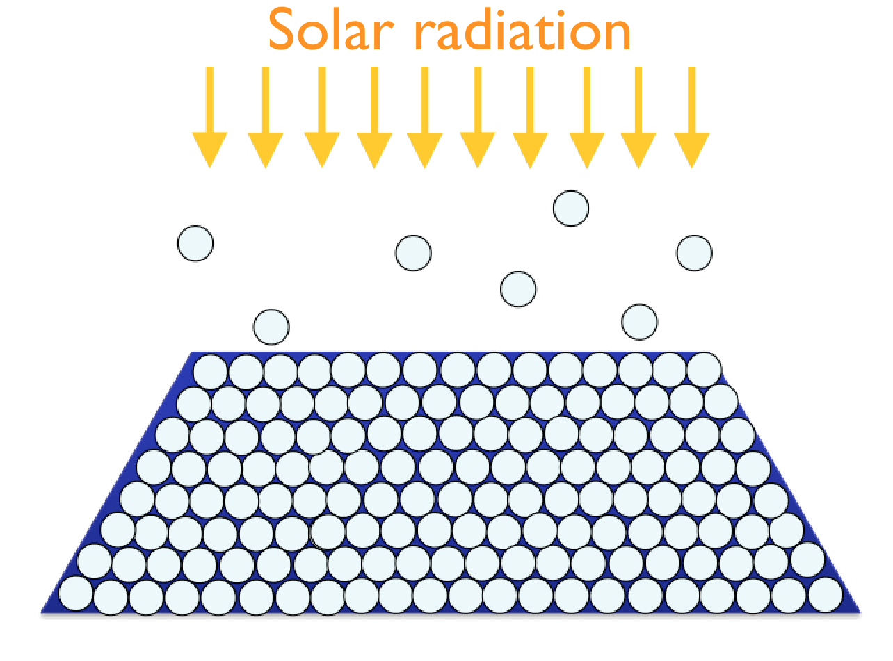
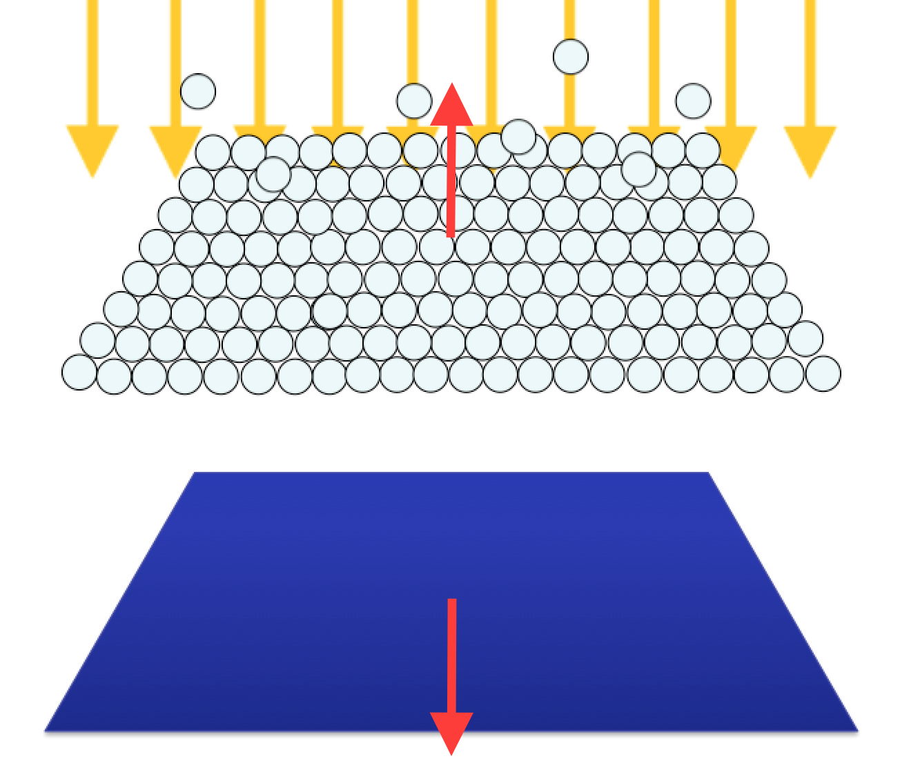
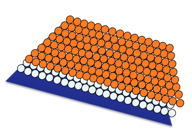
Consider a sail coated with a material that undergoes desorption for a particular temperature, corresponding to a specific heliocentric distance. As the sail gets closer to the Sun, its temperature increases, and some atoms of the coatings leave the surface. Once the right temperature is reached, the material desorbs, as shown in Fig. 1. If particles, molecules or atoms, of mass leave the sail’s surface at velocity , as follows from the law of conservation of total momentum, the sail of mass will move in the opposite direction with velocity , that is .
In order to find out the velocity of the sail, it is necessary to evaluate the thermal speed of the evaporated particles. The Maxwell speed distribution allows to calculate as the mean thermal velocity:
| (9) |
Assuming that the particles behave as ideal gas, and that they are identical but still distinguishable, the Maxwell velocity distribution function can be applied [12]:
| (10) |
where is the probability that a particle has its speed in the range at . Let be the number of atoms with speed in the range at , so with velocity magnitude between and . With the assumption that all the particles leave the substrate in a direction orthogonal to the surface, their momentum is . Using the latter expression and Eq. (10) the total momentum can be obtained by integrating it over to infinity:
| (11) |
From Eq. (11) follows that the momentum of thrust is proportional to the square root of the temperature. Since the acceleration of the solar sail is also proportional to the momentum,
| (12) |
it follows that even acceleration is proportional to and to the inverse of time. This result can be compared to the photon pressure acceleration in Eq. (7), which was strongly limited by temperature, being proportional to .
Thermal desorption for a sail coating
Now consider a sail coated with a material that undergoes thermal desorption. The proposed coating is in carbon, as suggested in Ref. [2]. The acceleration due to thermal desorption is given by Eq. (12), where is the number of particles desorbed, is the mass of desorbed atoms or molecules, is the temperature for which desorption occurs, is the sail mass and is the time needed for the physical process of thermal desorption to be completed.
Once the material is known is determined, and if also the thickness and the area of the sail, and respectively, are defined, one can find the number of atoms desorbed. In fact, being the sail’s material density and its volume, as one gets:
| (13) |
Then the number of atoms desorbed per unit area during the time, , is obtained from (3) if the activation energy is known (see Ref. [13, 14]). If the sail area is defined, is fixed, so the required desorption time can be found [15, 16]. However this approach would require very accurate information about the materials characteristics, and the activation energy varies in a wide range and would require ad hoc experiments to have reliable data. For this reason another approach was used: as suggested in Benford’s paper [2] a nominal rate of mass loss was chosen, . For a given sail area and thickness or loading factor , the mass of the sail is fixed. For each heliocentric distance (to which corresponds a defined temperature ) one can evaluate the mean thermal velocity using Eq. (9) that by means of (8) provides the acceleration due to desorption. Given a sail coating thickness , the density of the material and the area of the sail, the total mass required for the desorption is obtained, and then the desorption time dividing the mass over the rate of mass loss.
Solution of the problem
Considering an heliocentric distance (to which corresponds as will be shown in the next Section) the mean thermal velocity for Carbon is and the acceleration due to desorption . If the sail coating thickness is the total mass required for the desorption is , and the desorption time (almost 9 hours). Because the mass of the coating is not negligible with respect to the sail mass, and the desorption time is also relevant, the formula doesn’t apply. In fact, this analysis cannot neglect the variation of mass during the acceleration time. Being the mass of the coated sail , the force on the sail is:
| (14) |
whereas the force due to thermal desorption is:
| (15) |
By comparing these two equations one obtains a differential equation in :
| (16) |
that, by introducing the following notations,
can be re-written as:
| (17) |
One can solve Eq. (17) and obtain the expression for the velocity as function of time:
| (18) |
Temperature dependence on heliocentric distance
In the previous section the acceleration of the sail has been written as function of temperature, by means of Eqs. (7) and (12). However, temperature of the solar sail surface depends on the heliocentric distance [17]. The aim of this section is to determine how the temperature depends on heliocentric distance. Such analysis can be done based on the law of conservation of energy by considering the temperature dependence of the reflectivity, absorptivity and emissivity of solar sail materials [18].
Due to the interaction with the surface of the solar sail, the solar electromagnetic radiation can be reflected, absorbed or transmitted. Therefore, one can write:
| (19) |
where , and are the radiative or optical properties of the solar sail material: spectral (as they depend on wavelength) hemispherical (as they are not directional) reflectivity, absorptivity and transmissivity, respectively [19].
To evaluate the pressure exerted on the sail, it is necessary to consider the momentum transported not by a single photon, but by a flux of photons. Based on the inverse square law the energy flux (also said solar irradiance) depends on the distance of the body from the Sun as:
| (20) |
where is the Sun-Earth distance and is the Solar irradiance at Earth distance, defined through the solar luminosity .
Considering the sail pitch angle , the incident solar energy flux in (20) is the following:
| (21) |
The corresponding absorbed energy flux will be:
| (22) |
where the dependence on wavelength has been removed computing the spectral average, so considering the total hemispherical optical coefficients.
Once that energy has been absorbed, it can also be emitted from the surface, as a secondary process. From the Stefan-Boltzmann’s law, the rate of energy emitted from a surface at a certain temperature is proportional to the fourth power of the temperature. As a sail is usually composed by various films of different materials, in general its front and back sides will have different emissivity, and , respectively. Hence, the emitted energy flux, from front and back surfaces is:
| (23) |
From the law of conservation of energy the solar sail will be in thermal equilibrium if the total absorbed energy equals the total emitted energy. By applying the equality , the so known Kirchhoff’s law, and considering that from Eq. (21) the solar energy flux has an inverse square variation with the heliocentric distance , one can find the dependence of the sail temperature on the heliocentric distance as
| (24) |
If the front and back sides have almost equal emissivity (), the latter equation gives:
| (25) |
From the analysis of Eq. (25) it results that , but this is true only within the standard approach that considers the optical coefficients to have constant values and no dependence on temperature [20]. Experimental given data are and for Aluminum [21]. However recent studies show that reflectivity and emissivity also depend on temperature [18]. Although reflectivity dependence on temperature can be neglected, the same doesn’t apply for emissivity, which is directly proportional to the temperature as suggested by Parker and Abbott in Ref. [22]. The expression they found for the total hemispherical emissivity for metals is the following:
| (26) |
where is the electrical conductivity in , which is defined as the inverse of resistivity :
| (27) |
It has been shown with experimental results [21] that a very good approximation can be obtained considering only the first term of the Eq. (26), that leads to:
| (28) |
For Aluminum the coefficient in (28) is . The electrical resistivity of most materials changes with temperature. Usually a linear approximation is used:
| (29) |
where is called the temperature coefficient of resistivity, is a fixed reference temperature (commonly room temperature) and is the resistivity at temperature . Values for electrical conductivity, resistivity and temperature coefficient of various materials can be found in literature. Considering a reference temperature of , for Aluminum , and .
As it follows from (27) and (29), is almost inversely proportional to the temperature, this means that emissivity :
| (30) |
By introducing this analysis in Eq. (25) the dependence of temperature on the heliocentric distance varies as
| (31) |
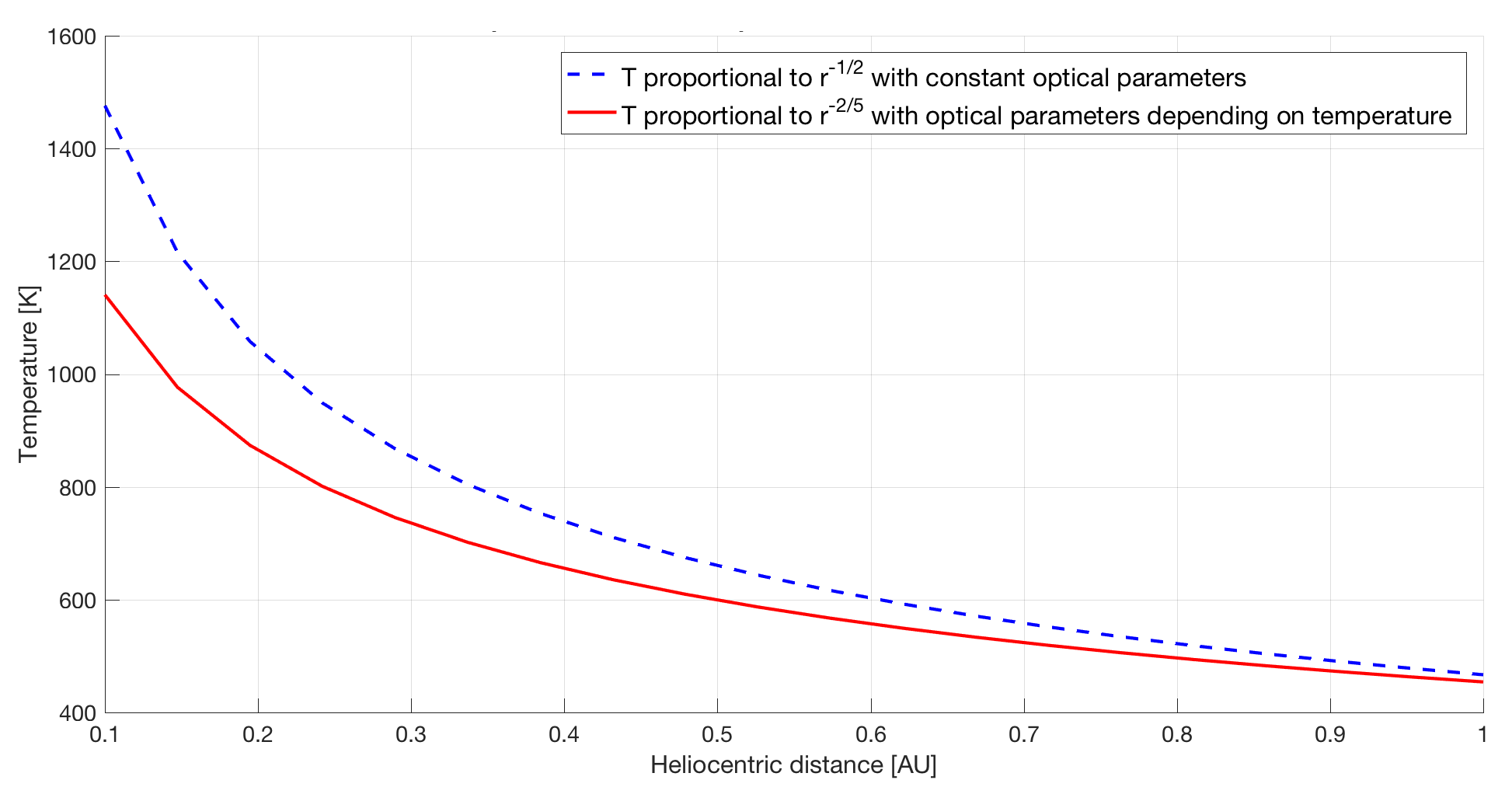
Dependence of the sail temperature on the heliocentric distance for a case of constant emissivity and, conversely, when emissivity of the solar sail material depends on temperature is shown in Fig. 2, and listed in Table 3. It is clear that, considering the temperature dependence of emissivity (solid curve), the sail temperature increases more slowly than in the case of constant emissivity (dashed curve), as the sail approaches the Sun [1]; this leads to the conclusion that the sail would be able to get closer to the Sun without degradation of its optical properties. Figure 2 compares Eq. (25), the blue line, to Eq. (31), the red line. In our calculations for both the Equations the sail pitch angle was considered to be and the transmissivity was neglected, as experimental data confirm it is a very small fraction (almost 2%) of the incoming solar energy flux.
| Distance [AU] | T [K] | T [K] |
|---|---|---|
| () | () | |
| 1476.1 | 1140.6 | |
| 1043.8 | 864.4 | |
| 852.2 | 735.0 | |
| 738.1 | 655.1 | |
| 660.1 | 599.2 | |
| 602.6 | 557.0 | |
| 557.9 | 523.7 | |
| 521.9 | 496.5 | |
| 492.0 | 473.6 | |
| 466.8 | 454.1 |
In our scenarios analysis the considered temperature will be the one deriving from the more accurate analysis with the thermal variation of optical properties of the sail material.
Proposed scenarios
This section will focus on the orbital mechanics of a solar sail accelerated by thermal desorption of coatings and different scenarios that could be considered. It is very important to remark that in order to have an effective desorption, high temperatures are required, so every scenario takes advantage of a passage extremely close to the Sun.
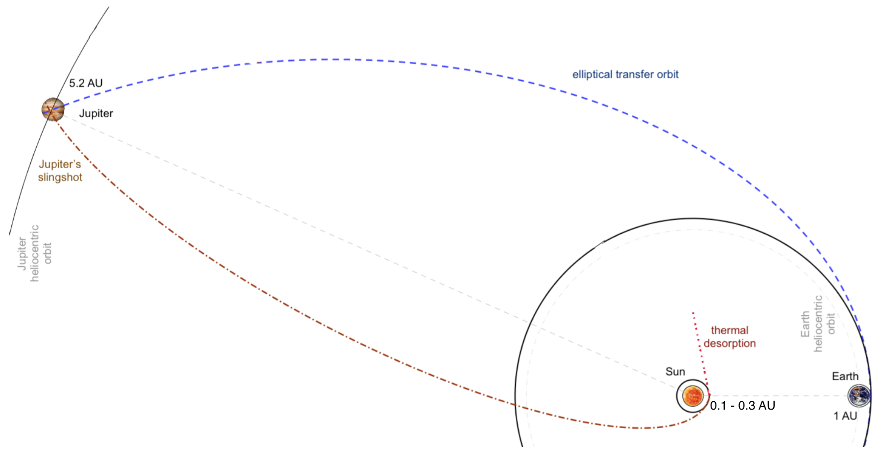
For every scenario the transfer orbit to the Sun is in dash-dot line, the thermal desorption from the perihelion distance is in dotted line. In solid line the orbits of the planets or the sail. For the second scenario, the transfer orbit from Earth to Jupiter is in dashed line.
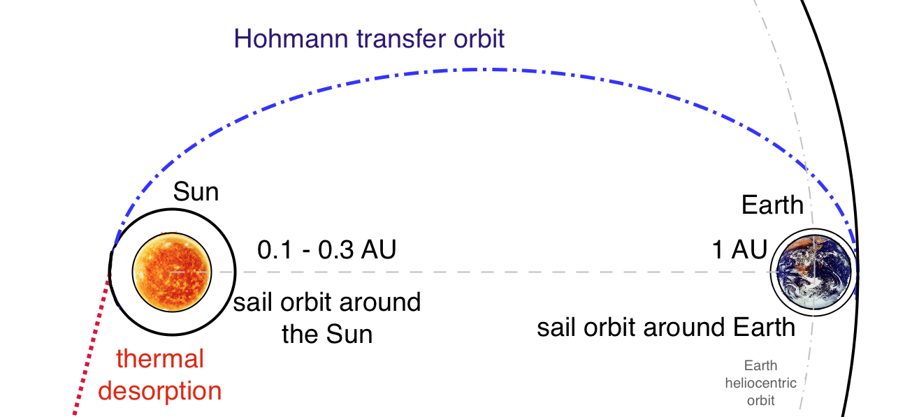
Hohmann transfer plus thermal desorption
This is the simplest scenario that can be esteemed. It involves a Hohmann transfer from Earth’s orbit to an orbit very close to the Sun, the perihelion of latter varies from 0.3 AU to 0.1 AU. The proposed sail would be carried to the perihelion with a conventional propulsion system and then be deployed there. The solar sail has one coat of the material that undergoes desorption at the temperature reached at the perihelion of the transfer orbit. The sail then escapes the Solar System. The schematic diagram for the first scenario is shown in Fig. 3.
Elliptical transfer plus Slingshot plus thermal desorption acceleration
In this scenario a generic elliptical transfer is performed from Earth’s orbit to Jupiter’s orbit. Then a Jupiter’s fly-by leads to the orbit close to the Sun, where the sail is deployed and thermal desorption accelerates it to the escape velocity. As in the previous case, the sail has one coat of the material that undergo desorption at the temperature reached at the perihelion. The corresponding schematic diagram for this scenario is shown in Fig. 4.
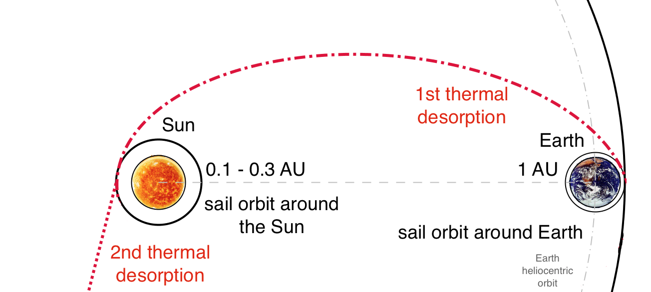
Two stage acceleration of the solar sail through thermal desorption
The proposed sail has two coats of the materials that undergo desorption at different solar sail temperatures depending on the heliocentric distance. The first desorption occurs at the Earth orbit and provides the thrust needed to propel the solar sail toward the Sun. When the solar sail approaches the Sun, its temperature increases, and the second coat undergoes desorption at the perihelion of the heliocentric escape orbit. This provides a second thrust and boosts the solar sail to its escape velocity. The schematic diagram for this scenario is shown in Fig. 6. Note that in this scenario the sail is deployed from the beginning, so it will actually approach the Sun obeying to the conventional solar sail orbital dynamics, with a typical spiral logarithmic trajectory. It is important to remark that, although we are considering an high-performance solar sail (so with lightness number ) for our mission, the that has to be considered, in order to evaluate the spiral logarithmic trajectory, is the one of the inner coating, as the outer would have left the sail at the beginning of the heliocentric transfer. The coating material must have good properties for desorption, so we accept a low lightness number for the first part of the mission (resulting basically in a longer time required to get to the perihelion).
These three scenarios are analyzed and compared. As a preliminary analysis the planets are considered point-like. In the heliocentric reference frame, assuming by approximation that the Earth’s orbit is almost circular, with radius , the sail has to be transferred to an inner orbit closer to the Sun, of radius , in order to escape the Solar System. The transfer between these two coplanar circular orbits is different for every scenario.
Results
For the sake of brevity we will skip the orbital dynamics calculations, that are nothing but the application of well-known conventional formulas [23], and go directly to the results that show the positive contribution of thermal desorption. In Table 5 we present the results obtained for all the proposed scenarios. Solving Eq. (16) the final velocity of the sail after the desorption time can be determined. By contrast, is the velocity that the sail has when it reaches the perihelion, before desorption occurs, and it comes from the orbital dynamics of: i) a conventional spacecraft for the first two scenarios; ii) a solar sail with constant pitch angle for the third scenario.
| 1st scenario | ||||
|---|---|---|---|---|
| 0.3 | 0.2 | 0.1 | ||
| 67.39 | 85.91 | 126.89 | ||
| 167.16 | 213.43 | 315.81 | ||
| 170.65 | 217.54 | 321.43 | ||
| 35.9 | 45.8 | 67.7 | ||
| 2nd scenario | ||||
|---|---|---|---|---|
| 0.3 | 0.2 | 0.1 | ||
| 73.24 | 91.28 | 129.11 | ||
| 181.82 | 226.90 | 321.44 | ||
| 185.04 | 230.76 | 326.90 | ||
| 39.0 | 48.7 | 68.9 | ||
| 3rd scenario | ||||
|---|---|---|---|---|
| 0.3 | 0.2 | 0.1 | ||
| 54.33 | 64.77 | 91.60 | ||
| 134.42 | 160.44 | 227.41 | ||
| 138.74 | 165.87 | 235.07 | ||
| 29.2 | 34.9 | 49.5 | ||
The final cruise speed is obtained from the application of the law of conservation of energy, and from it comes the distance travelled per year. First of all, one can notice that when reducing the heliocentric distance of perihelion, the speed increases for all the three scenarios. By analyzing the results it is clear that the higher velocity is reached at the perihelion, the greater will be the contribution of desorption and consequently the cruise speed of the solar sail. In terms of cruise speed and distance covered per year, the best scenario is always the second one, that takes advantage of a profitable planetary flyby. In fact, for the heliocentric distance of the cruise speed obtained is extremely high: almost . A solar sail traveling at this speed would cover a distance of per year. This means that it would take only about 8 years to reach the Sun gravity focus, at . Note that for a conventional solar sail typical values of cruise speed correspond to .
It is also evident that the first and second scenario have very similar values of speed. However, the second scenario would be preferable for a relevant reason, that cannot be deducted from the table below, and it is that the required for the first scenario is much more expansive than the one for the scenario with Jupiter flyby. In particular, for the most demanding heliocentric distance to reach, , the first scenario requires a , whereas for the second scenario . The only disadvantage of the second scenario is that it would require more time: the Hohmann transfer to would need just 73 days, instead the flyby scenario requires 558 days only to get to Jupiter, and it is necessary to add to this value also the days required to get back to . From the point of view of time required, the second scenario is, with no doubt, the most critical one. In fact even the spiral logarithmic trajectory of the sail of the third scenario would be faster: 474 days required with and only 107 days with , respectively.
We considered because, as previously explained, the required would dramatically grow for . In fact, for the third scenario with , whereas with . Let us mention that the required for the third scenario is given starting from a LEO, so it cannot be compared to the previous two scenarios, where the launch was included in the budget calculations.
To conclude, the performance of a two steps acceleration of the solar sail by thermal desorption are lower than the ones than it is possible to achieve with a Jupiter flyby, in terms of velocity reached and distance covered per year. However, this configuration could be advantageous in terms of times and required.
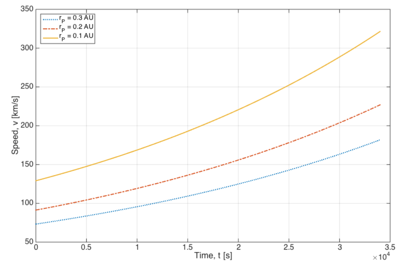
Let us put in evidence the benefits of thermal desorption: if sapiently driven, this phenomenon can enhance a lot the speed of the solar sail, as one can see by simply comparing the values of and for all the scenarios. The acceleration due to desorption is of the order of , whereas that of photon pressure is a few , for this reason the photon pressure acceleration is neglected during the short desorption time. Fig. 7 shows the gain in velocity due to desorption for the best scenario. Eq. 12 shows that the acceleration of desorption is proportional to the temperature, and this is also confirmed in the graph.
Conclusions
Let us summarize our work and come to conclusions. The concept on which all the study is based is that for extrasolar space exploration it might be very convenient to take advantage of space environmental effects, such as solar radiation heating. A solar sail could be accelerated if coated by materials that undergo thermal desorption at a particular temperature. Thermal desorption is a physical process of mass loss which dominates all other similar processes and it can provide additional thrust as heating liberates atoms, embedded on the surface of a solar sail.
We considered a solar sail coated with one or two materials that undergo thermal desorption at a specific temperature, as a result of heating by solar radiation at a particular heliocentric distance, and focused on the orbital dynamics of three scenarios that only differ in the way the sail approaches the Sun. In every case once the perihelion is reached, the sail coat undergoes thermal desorption. When the desorption process ends, the sail then escapes the solar system having the conventional acceleration due to solar radiation pressure. Our study analyzed and compared three different scenarios in which thermal desorption comes beside traditional propulsion systems for extrasolar space exploration.
The first scenario consists of a Hohmann transfer plus thermal desorption. In this scenario the sail is carried as a payload to the perihelion with a conventional propulsion system by a Hohmann transfer from Earth’s orbit to an orbit very close to the Sun, the perihelion of latter varies from 0.3 AU to 0.1 AU, and then is deployed there. The second proposed scenario consists of an elliptical transfer plus slingshot plus thermal desorption. In this scenario the transfer occurs from Earth’s orbit to Jupiter’s orbit and then a Jupiter’s fly-by leads to the orbit close to the Sun, where the sail is deployed. The last and third scenario consists of a two stage acceleration of the solar sail through thermal desorption. The proposed sail has two coats of the materials that undergo thermal desorption at different temperatures depending on the heliocentric distance. The first desorption occurs at the Earth orbit and provides the thrust needed to propel the solar sail toward the Sun. The second desorption is the same as in the other scenarios.
The comparison of the scenarios shows that the second one is the best in terms of cruise speed and distance covered per year. In fact, for the heliocentric distance of the cruise speed obtained is almost , that leads to travelled per year. For all the scenarios, however, the great advantage of thermal desorption is clear and evident.
Our study is a preliminary design of a solar sail mission considering the innovative contribution of thermal desorption of one or more coatings. At this stage many assumptions were made in order to simplify the solution of the problem. Eventually the study could be improved and refined. For example, for the third scenario a better result could be obtained considering the sail pitch angle not constant but variable, with a numerical methods optimization. Also, let us mention that the perturbations of other bodies were not taken into account. It could be done with the help of numerical analysis, starting from the patched conics method and propagating the orbit with some tools such as STK. Another relevant assumption is that the Sun was always considered as point-like body. But when approaching the Sun very close, the inverse square law results to be inadequate and requires consideration of the finite size of the Sun. This topic is treated in [20].
The natural prosecution of this work would be a detailed research on materials, in order to find out their characteristics, performances and desorption temperature suitable for solar sailing. For what concerns materials, in fact, the research could be extended widely. Carbon nanotubes coatings have been suggested for solar sails [1, 24], but there could be better solutions for the specific mission proposed. This would require also laboratory experiments to evaluate activation energies and all the other properties involved in the chemical thermal desorption process.
Acknowledgements
This research was supported by PSC CUNY Grant: award # 68298-0046.
?refname?
- [1] R. Ya. Kezerashvili. Space exploration with a solar sail coated by materials that undergo thermal desorption. Acta Astronaut., 117:231-237, 2015.
- [2] G. Benford and J. Benford. Acceleration of sails by thermal desorption of coatings. Acta Astronaut., 56:593-599, 2005.
- [3] G. Vulpetti, L. Johnson, and G. L. Matloff. Solar Sails - A novel approach to interplanetary travel. Copernicus Books, 2008.
- [4] J. Benford and G. Benford. Flight of microwave driven sails: Experiments and applications. AIP Conference Proceedings, 664:303-312, 2003.
- [5] H. Ulbricht, R. Zacharia, N. Cindir, and T. Hertel. Thermal desorption of gases and solvents from graphite and carbon nanotube surfaces. Carbon, 44:2931-2942, 2006.
- [6] P. A. Redhead. Thermal desorption of gases. Vacuum, 12:203-211, 1962.
- [7] J. L. Beeby. A theory of desorption and surface processes - a general formulation. Surface Science, 114:118-136, 1982.
- [8] G. Benford and P. Nissenson. Reducing solar sail escape times from earth orbit using beamed energy. Acta Astronaut., 58:175-184, 2006.
- [9] G. Benford and J. Benford. Desorption assisted sun diver missions. AIP Conference Proceedings, 608:462-469, 2002.
- [10] R. L. Forward. Starwisp: An ultra-light interstellar probe. J. Spacecraft, 22:345, 1985.
- [11] R. L. Forward. Roundtrip interstellar travel using laser-pushed light sails. J. Spacecraft, 21:187, 1984.
- [12] C. Kittel and H. Kroemer. Thermal Physics. W. H. Freeman and Company, 1980.
- [13] H. Ulbricht, G. Moos, and T. Hertel. Interaction of c60 with carbon nanotubes and graphite. Physical Review Letters, 90(9):095501-4, 2003.
- [14] R. Zacharia, H. Ulbricht, and T. Hertel. The interlayer cohesive energy of graphite from thermal desorption of polyaromatic hydrocarbons. arXiv:cond-mat/0308451, 2003.
- [15] M. Oba, H. Mita, and A. Shimoyama. Determination of activation energy and pre-exponential factor for individual compounds on release from kerogen by a laboratory heating experiment. Geochemical Journal, 36:51-60, 2002.
- [16] M. Yu and Z. Li et al. Desorption activation energy of dibenzothiophene on the activated carbons modified by different metal salt solutions. Chemical Engineering Journal, 132:233-239, 2007.
- [17] E. Ancona and R. Ya. Kezerashvili. Temperature restrictions for materials used in aerospace industry for the near-sun orbits. [Manuscript Submitted for Conference IAC-16-C2.6.6.32493], 2016.
- [18] R. Ya. Kezerashvili. Solar sail: Materials and space environmental effects. in the book: M. Macdonald (Ed.), Advances in Solar Sailing, Springer Praxis Books, Berlin, Heidelberg, pages 573-592, 2014.
- [19] Y. A. Çengel and A. J. Ghajar. Heat and Mass Transfer - Fundamentals and Applications. McGraw-Hill Education, 5th edition, 2015.
- [20] C. R. McInnes. Solar Sailing - Technology, Dynamics and Mission Applications. Springer, 1999.
- [21] M. F. Modest. Radiative Heat Transfer. McGraw-Hill, 1993.
- [22] W. J. Parker and G. L. Abbott. Theoretical and experimental studies of the total emittance of metals. Symposium on Thermal Radiation of Solids, NASA SP-55, pages 11-28, 1965.
- [23] R. R. Bate, D. D. Mueller, and J. E. White. Fundamentals of Astrodynamics. Dover Publications, Inc., 1971.
- [24] E. Ancona. Two steps acceleration of a solar sail by thermal desorption of coatings and Poynting- Robertson effect [unpublished manuscript]. Master’s thesis, 129 pages, Politecnico di Torino, 2016.