Experimental Study of a Triode Reflex Geometry Vircator
Abstract
Triode reflex geometry vircator operating within 3.0 - 4.2 GHz range with efficiency up to 6 is developed and experimentally investigated. Shiftable reflectors are shown to enable frequency tuning and output power control. Radiation frequency and power are analyzed for different cathode-anode gap values and varied reflector positions.
I Introduction
Microwave devices with a virtual cathode in a triode reflex geometry attract many researches by the ability to operate without a guiding magnetic field, enhanced tunability of the operation frequency and high output power [1, 2, 3, 4, 5, 6, 7]. The reflex triode vircator modified with the inclusion of reflecting strips [2] provided microwave peak power output as high as 330 MW at 11 efficiency.
In the present paper the triode reflex geometry vircator with two shiftable reflectors (disc-shaped and reflecting stripes) is experimentally studied. Radiation frequency and power are analyzed for different cathode-anode gap values and varied reflector positions.
II System description
II-A Pulsed power supply
The developed triode reflex geometry vircator is driven by a pulsed power supply, similar to that in [8], using a 30 kJ/100 kV capacitor bank and an exploding wire array (EWA) capable of generating a 600 kV voltage pulse.
A high-voltage pulse of positive polarity is applied to the centered in the vacuum chamber anode of 200 mm diameter. The EWA consists of parallel connected oxygen-free high-conductivity (OFHC) 99.99 purity copper wires 100 m in diameter. The length and the number of wires can vary to match the EWA and vircator impedances. The EWA case is designed to be filled with gas (nitrogen or nitrogen and mixture) at pressures up to 0.6 MPa, but the array can also be fired in air. A pressurized spark gap sharpens the high-voltage output, so that the diode voltage pulse approaching 460 kV with a rise time well below 100 ns is generated: the gas pressure and the gap between the electrodes can be varied.
II-B Triode reflex geometry vircator
The vacuum chamber of 300 mm diameter and 600 mm length encloses the triode reflex geometry vircator operating in the frequency range from 3.0 to 4.2 GHz (see Fig. 3 - Fig. 5).
Shown in Fig. 3, and are the variable distances from the cathode axis to the disk-shaped and output shiftable reflectors, respectively.
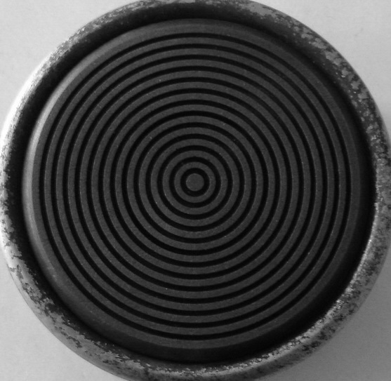
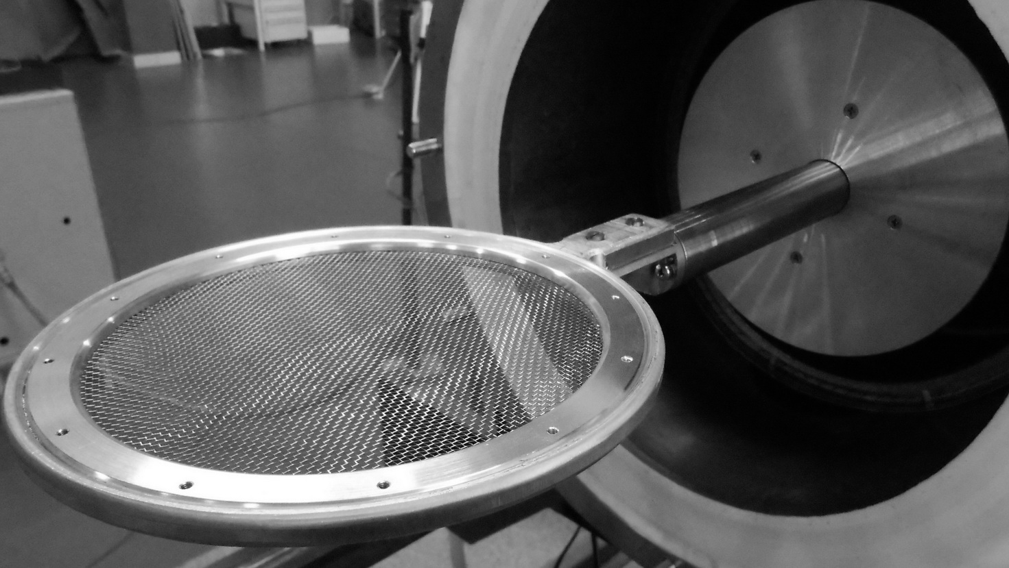
Stainless steel woven anode mesh with 77 geometric transparency is used in the experiments; the diameter of the mesh thread is 224 m. Solid type cathode of 60 mm diameter with surface hatching is made of dense fine-grained graphite MPG-8 (produced by NIIGraphite, Moscow, Russia). The output reflector consists of two rectangular brass stripes 40 mm in width and 100 mm in length, housed at a variable distance from the output window, normally to the anode plane position.
The value of the cathode-anode gap can be fixed with 0.1 mm accuracy. Coplanarity of cathode and anode surfaces is controlled. The cathode-anode gap value and reflector positions (defined by and ) can be tuned to provide stable single frequency generation and the highest output power.
II-C Diagnostic equipment
Three Rogowski coils enable detecting the current derivatives in the system at points 1, 2, and 3 in Fig. 2 Measured inductances and resistances in the circuit allow evaluating the EWA voltage and the voltage applied to the cathode. The microwave emission is detected at a distance of 11.5 m from the output window in the main lobe direction by two receiving antennas Geozondas 1-4.5GHz and Tektronix oscilloscopes TDS7704 and TDS7354. All the measuring channels are synchronized.
III Experimental results
The experimental investigation of a triode reflex geometry vircator was intended to ascertain the system parameters providing stable, single frequency, and high-power microwave generation. System operation was analyzed for different and values and cathode-anode gaps. Experimental results obtained for 3 cases are presented:
1. mm and mm with cathode anode gap values from 16 to 20 mm;
2. mm and mm with cathode anode gap values from 16 to 18 mm;
3. mm with removed reflecting stripes at 16 mm cathode-anode gap 16 mm.
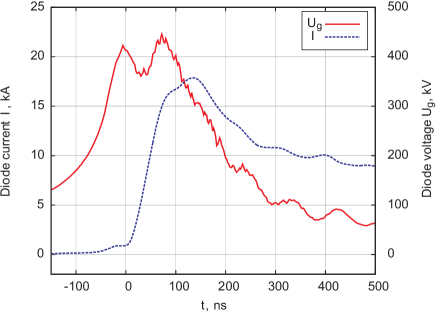
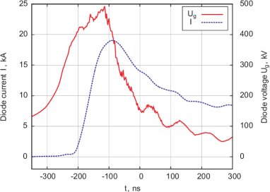
The typical voltage and current signals obtained for EWA containing 21 wires of 750 mm length are presented in Fig. 6. Two peaks emerged on the voltage curve: the first one (left) corresponded to spark gap closing and the second (right) marked the maximum diode voltage. The maximum diode voltage was as high as 430 kV and the amplitude of electron beam current was about 17 kA.
Knowing the gain and directivity of the system output and the parameters of the receiving antenna, we can convert the electric field strength measured at a certain distance from the output window to the radiated power.
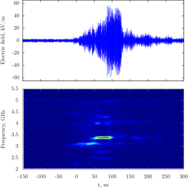
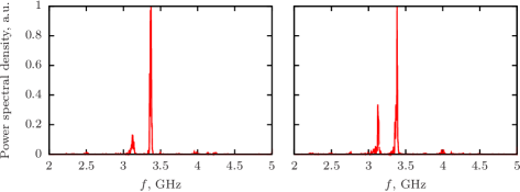
The maximum radiated power for reflector positions mm and mm was observed at cathode-anode gap 17 mm. The detected microwave signal and its spectral content are shown in Fig. 7 - Fig. 8: frequency, peak power and maximal electric field strength at 11.5 m distance from the output window measured 3.4 GHz , 400 MW and 55 kV/m, respectively. Radiation spectra shown in Fig. 8 were obtained in different shots at similar system parameters. Two close frequencies with different spectral power were detected: 3.37 GHz stronger line and much weaker 3.13 GHz one. Spectra a) and b) in Fig. 8 demonstrate maximal and minimal observed difference in spectral power for these two lines.
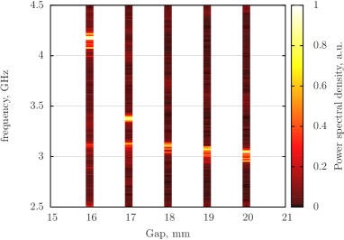
Variation of the cathode-anode gap value over the range 20 to 17 mm demonstrated smooth change of the radiation frequency within the range 3.0 to 3.37 GHz (see Fig. 9). In each diagram zone, which corresponds to the fixed cathode-anode gap value, the sum of frequency spectrums obtained in several experiments under similar conditions is presented. Change of the cathode anode gap value from 17 to 16 mm at fixed position of the output reflector lead to the hop of the radiation frequency from 3.37 to 4.16 GHz, which is also shown in Fig. 9.
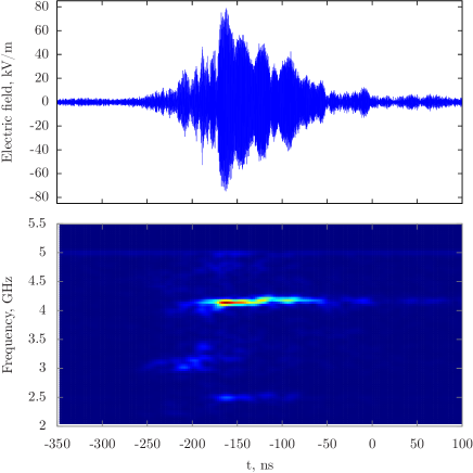
The maximum radiated power in the triode reflex geometry vircator with reflector positions mm and mm was observed at cathode-anode gap 16 mm. About 460 MW at 4.16 GHz frequency was produced at maximum diode voltage as high as 460 kV and amplitude of electron beam current 18 kA (see Fig. 10). Detected microwave signal with electric field strength amplitude kV/m and its spectral content are shown in Fig. 11 - Fig. 12. Cathode-anode gap change to 17 and 18 mm resulted in spectrum broadening and shift of its central frequency. Detected microwave signal and its spectral content obtained in experiments with reflector positions =290 mm and =164 mm at cathode-anode gap 18 mm are shown in Fig. 13.
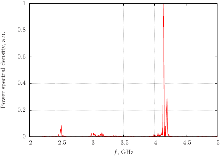

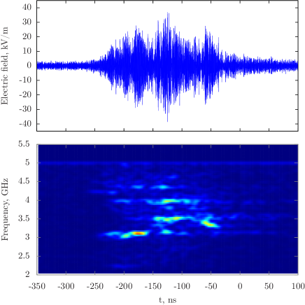
Triode reflex geometry vircator was also studied without shiftable output reflector. Reflecting stripes of the output reflector were dismounted, while the disk-shaped reflector was fixed at the position with =290 mm. The complicated multifrequency generation over the range 3.0 to 4.2 GHz obtained in the experiment is shown in Fig. 14. The electric field strength value measured at a 11.5 m distance from the output window in the main lobe direction in the series of experiments did not exceed 35 kV/m (see Fig. 14).
IV Conclusion
Triode reflex geometry vircator operating within 3.0 - 3.37 GHz and 4.0 - 4.2 GHz ranges with efficiency up to 6 was developed and experimentally investigated. Shiftable reflectors were shown to enable frequency tuning and output power control. Radiation frequency and power were analyzed for different cathode-anode gap values and varied reflector positions. The highest radiation power of 400 and 460 MW was obtained in the experiments with radiation frequency 3.37 and 4.16 GHz, respectively.
Significant influence of the output reflector on both the radiation efficiency and frequency is shown. Application of the output reflector enabled to achieve 1.6 times higher electric field strength value in the main lobe direction as compared to the case when reflector was absent. The influence of the cathode-anode gap value is also considered.
Acknowledgment
The authors would like to thank Victor Evdokimov for the sophisticated system design and Nikolai Belous for permanent involvement in the experimental activities.
References
- [1] A.N. Didenko, Generation of high power RF pulses in magnetron and reflex triode systems, High Power Electron and Ion Beam Research and Technology, Proc. III Intern. Conf., Novosibirsk, 1979, V. 2, pp. 683-691.
- [2] J.J. Mankowski, Xupeng Chen, J.C. Dickens, Magne Kristiansen, Experimental Optimization of a Reflex Triode Virtual Cathode Oscillator, High-Power Particle Beams, BEAMS 2004, pp. 426 - 429.
- [3] W. Jiang, N. Shimada, S.D. Prasad, K. Yatsui, Experimental and Simulation Studies of New Configuration of Virtual Cathode Oscillator,IEEE Trans. Plasma Sci., vol. 32, No. 1, 2004, pp. 54-59.
- [4] L. Liu, L.M. Li, X.P. Zhang, J.C. Wen, H. Wan, Y.Z. Zhang, Efficiency enhancement of reflex triode virtual cathode oscillator using the carbon fiber cathode, IEEE Trans. Plasma Sci., vol. 35, no. 2, pp. 361-368, 2007.
- [5] V.P. Grigoryiev, A.G. Zherlitsyn, T.V. Koval, G.V. Melnikov, P.Ya. Isakov, Mode Structure Research of a Field in the Triode with the Virtual Cathode with an Active Feedback,Proc. 14th Symposium on High Current Electronics,Tomsk, Russia,Izvestiya Vuzov, Physics, 2006, V.40, no.11, pp. 372-375.
- [6] A.G. Zherlitsyn, G.V. Mel’nikov,P.Ya. Isakov, Effect of Feedback on the Microwave Radiation in a Triode with a Virtual Cathode,Journal of Communications Technology and Electronics, 2007, Vol. 52, No. 7, pp. 798-802.
- [7] Y. Chen, J. Mankowski, J. Walter, M. Kristiansen, Cathode and Anode Optimization in a Virtual Cathode Oscillator,IEEE Transactions on Dielectrics and Electrical Insulation, Vol.14, Is. 4, pp. 1037 - 1044, 2007.
- [8] V. Baryshevsky, A. Gurinovich, E. Gurnevich, P. Molchanov. Experimental Study of an Axial Vircator with Resonant Cavity, IEEE Transactions on Plasma Science, v. 43, No. 10, pp. 3507-3511, 2015.