Practical Data Compression
for Modern Memory Hierarchies
Abstract
Although compression has been widely used for decades to reduce file sizes (thereby conserving storage capacity and network bandwidth when transferring files), there has been limited use of hardware-based compression within modern memory hierarchies of commodity systems. Why not? Especially as programs become increasingly data-intensive, the capacity and bandwidth within the memory hierarchy (including caches, main memory, and their associated interconnects) have already become increasingly important bottlenecks. If hardware-based data compression could be applied successfully to the memory hierarchy, it could potentially relieve pressure on these bottlenecks by increasing effective capacity, increasing effective bandwidth, and even reducing energy consumption.
In this thesis, we describe a new, practical approach to integrating hardware-based data compression within the memory hierarchy, including on-chip caches, main memory, and both on-chip and off-chip interconnects. This new approach is fast, simple, and effective in saving storage space. A key insight in our approach is that access time (including decompression latency) is critical in modern memory hierarchies. By combining inexpensive hardware support with modest OS support, our holistic approach to compression achieves substantial improvements in performance and energy efficiency across the memory hierarchy. Using this new approach, we make several major contributions in this thesis.
First, we propose a new compression algorithm, Base-Delta-Immediate Compression (BI), that achieves high compression ratio with very low compression/decompression latency. BI exploits the existing low dynamic range of values present in many cache lines to compress them to smaller sizes using Base+Delta encoding.
Second, we observe that the compressed size of a cache block can be indicative of its reuse. We use this observation to develop a new cache insertion policy for compressed caches, the Size-based Insertion Policy (SIP), which uses the size of a compressed block as one of the metrics to predict its potential future reuse.
Third, we propose a new main memory compression framework, Linearly Compressed Pages (LCP), that significantly reduces the complexity and power cost of supporting main memory compression. We demonstrate that any compression algorithm can be adapted to fit the requirements of LCP, and that LCP can be efficiently integrated with the existing cache compression designs, avoiding extra compression/decompression.
Finally, in addition to exploring compression-related issues and enabling practical solutions in modern CPU systems, we discover new problems in realizing hardware-based compression for GPU-based systems and develop new solutions to solve these problems.
Acknowledgments
First of all, I would like to thank my advisers, Todd Mowry and Onur Mutlu, for always trusting me in my research experiments, giving me enough resources and opportunities to improve my work, as well as my presentation and writing skills.
I am grateful to Michael Kozuch and Phillip Gibbons for being both my mentors and collaborators. I am grateful to the members of my PhD committee: Kayvon Fatahalian, David Wood, and Doug Burger for their valuable feedback and for making the final steps towards my PhD very smooth. I am grateful to Deb Cavlovich who allowed me to focus on my research by magically solving all other problems.
I am grateful to SAFARI group members that were more than just lab mates. Vivek Seshadri was always supportive for my crazy ideas and was willing to dedicate his time and energy to help me in my work. Chris Fallin was a rare example of pure smartness mixed with great work ethic, but still always had time for an interesting discussion. From Yoongu Kim I learned a lot about the importance of details, and hopefully I learned something from his aesthetic sense as well. Lavanya Subramanian was my fellow cubic mate who showed me an example on how to successfully mix work with personal life and how to be supportive for others. Justin Meza helped me to improve my presentation and writing skills in a very friendly manner (as everything else he does). Donghyuk Lee taught me everything I know about DRAM and was always an example of work dedication for me. Nandita Vijaykumar was my mentee, collaborator, and mentor all at the same time, but, most importantly, a friend that was always willing to help. Rachata Ausavarungnirun was our food guru and one of the most reliable and friendly people in the group. Hongyi Xin reminded me about everything I almost forgot from biology and history classes, and also taught me everything I know now in the amazing field of bioinformatics. Kevin Chang and Kevin Hsieh were always helpful and supportive when it matters most. Samira Khan was always available for a friendly chat when I really need it. Saugata Ghose was my rescue guy during our amazing trip to Prague. I also thank other members of the SAFARI group for their assistance and support: HanBin Yoon, Jamie Liu, Ben Jaiyen, Yixin Luo, Yang Li, and Amirali Boroumand.
Michelle Goodstein, Olatunji Ruwase and Evangelos Vlachos, senior PhD students, shared their experience and provided a lot of feedback early in my career. I am grateful to Tyler Huberty and Rui Cai for contributing a lot to my research and for being excellent undergraduate/masters researchers who selected me as a mentor from all the other options they had.
During my time at Carnegie Mellon, I met a lot of wonderful people: Michael Papamichael, Gabe Weisz, Alexey Tumanov, Danai Koutra and many others who helped and supported me in many different ways. I am also grateful to people at PDL and CALCM groups for accepting me in their communities.
I am grateful to my internship mentors for making my work in their companies mutually successful for both sides. At Microsoft Research, I had the privilege to closely work with Karin Strauss, Dimitrios Lymberopoulos, Oriana Riva, Ella Bounimova, Patrice Godefroid, and David Molnar. At NVIDIA Research, I had the privilege to closely work with Evgeny Bolotin, Steve Keckler, and Mike O’Connor. I am also grateful to my amazing collaborators from Georgia Tech: Hadi Esmaeilzadeh, Amir Yazdanbaksh, and Bradley Thwaites.
And last, but not least, I would like to acknowledge the enormous love and support that I received from my family: my wife Daria and our daughter Alyssa, my parents: Gennady and Larissa, and my brother Evgeny.
Chapter 1 Introduction
The recent Big Data revolution has had a transformative effect on many areas of science and technology [169]. Indeed, a key factor that has made Cloud Computing attractive is the ability to perform computation near these massive data sets. As we look toward the future, where our ability to capture detailed data streams from our environment is only expected to increase, it seems clear that many important computations will operate on increasingly larger data set sizes.
Unfortunately, data-intensive computing creates significant challenges for system designers. In particular, the large volume and flow of data places significant stress on the capacity and bandwidth across the many layers that comprise modern memory hierarchies, thereby making it difficult to deliver high performance at low cost with minimal energy consumption.
1.1 Focus of This Dissertation: Efficiency of the Memory Hierarchy
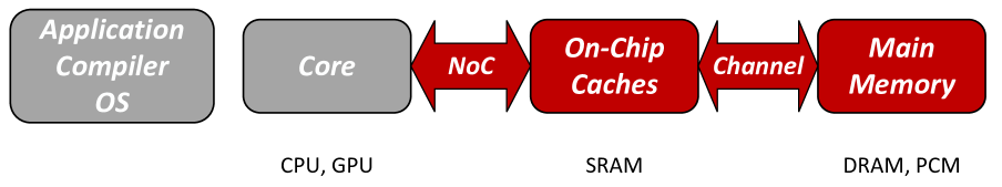
This dissertation focuses on performance and energy efficiency of the modern memory hierarchies. We observe that existing systems have significant redundancy in the data (i) stored in the memory hierarchies (e.g., main memory, on-chip caches) and (ii) transferred across existing communication channels (e.g., off-chip bus and on-chip interconnect). Figure 1.1 shows parts of the system stack where we aim to apply data compression (in red/dark).
In this dissertation, we first propose a simple and fast yet efficient compression algorithm that is suitable for on-chip cache compression. This algorithm solves one of the key challenges for cache compression: achieving low decompression latency, which is on the critical path of the execution. Then, we show that compressed cache block size is a new important factor when making cache replacement decisions that helps to outperform state-of-the-art cache replacement mechanisms.
We then propose a new design for main memory compression that solves a key challenge in realizing data compression in main memory: the disparity between how the data is stored (i.e., at a page granularity) and how it is accessed (i.e., at a cache line granularity).
Finally, we show that bandwidth compression—both on-chip and off-chip—can be efficient in providing high effective bandwidth in the context of modern GPUs (with more than a hundred real applications evaluated). At the same time, we find that there is a new important problem with bandwidth compression that makes it potentially energy inefficient – the significant increase in the number of bit toggles (i.e., the number of transitions between zeros and ones) that leads to an increase in dynamic energy. We provide an efficient solution to this problem.
1.1.1 A Compelling Possibility: Compressing Data throughout the Full Memory Hierarchy
At first glance, data compression may seem like an obvious approach to reducing the negative impacts of processing large amounts of data. In theory, if data compression could effectively reduce the size of the data without introducing significant overheads, it would relieve pressure on both the capacity of the various layers of the memory hierarchy (including caches, DRAM, non-volatile memory technologies, etc.) as well as the bandwidth of the communication channels (including memory buses, etc.) that transfer data between these layers. This in turn would allow system designers to avoid over-provisioning these resources, since they could deliver performance more efficiently as a function of system cost and/or power budget. Perhaps surprisingly, although forms of data compression have been used for many years to reduce file system storage requirements (e.g., by using gzip to compress files), there has been little to no use of compression within modern memory hierarchies.111The only real exception that we are aware of is IBM’s MXT technology [3], which was shipped in commercial products roughly 10 years ago, but which has not become widely adopted. Why not?
1.1.2 Why Traditional Data Compression Is Ineffective for Modern Memory Systems
Traditional file compression algorithms such as Lempel-Ziv [268] achieve high compression ratios by scanning through the file from the beginning, building up a dictionary of common character sequences (which is stored within the compressed file and used for decompression). In the context of storing files on disk, variations of Lempel-Ziv have been very popular because files are often accessed as sequential streams, and because the large decompression latencies are considered to be acceptable given that (i) disk accesses are already slow, and (ii) saving as much disk space as possible is typically a very high priority.
In contrast to accessing compressed files on disk, two things are fundamentally different when a processor accesses data (via loads and stores) within its memory hierarchy: (i) latency is extremely critical, and (ii) data is commonly accessed randomly (rather than sequentially). Because processor performance is so sensitive to memory access latency, it is critical that the decompression latency must be as small as possible when accessing compressed data within the memory hierarchy. Otherwise, system designers and users will quickly become disenchanted with memory compression if it costs them significant performance. Ideally, if decompression latency is small enough, compression within the memory hierarchy should actually improve performance by improving cache hit rates and reducing bandwidth-related stalls. The fact that main memory is randomly accessed creates additional challenges, including locating (as well as decompressing) arbitrary blocks of data efficiently, plus achieving significant compression ratios without being able to use Lempel-Ziv’s approach of building up dictionaries over large access streams.
1.2 Related Work
Several prior works have proposed different mechanisms to improve the efficiency of the memory hierarchy to provide (i) higher capacity, (ii) higher bandwidth, (iii) lower latency, and (iv) higher energy efficiency. In this section, we summarize some of the approaches that are related to our work. We summarize those works based on their high-level insight and compare them with the mechanisms proposed in this thesis.
1.2.1 3D-Stacked DRAM Architectures
One of the major limitations of the existing DRAM-based memories is their limited off-chip bandwidth. One way to overcome this limitation is by vertically stacking multiple DRAM chips that provide wider IO interfaces, and hence increase the available off-chip bandwidth to improve performance. Many recent works have proposed designs and architectures based on this idea (e.g., [101, 99, 99, 131, 84, 86]) to get higher off-chip bandwidth, or to utilize 3D-stacked memory’s higher capacity as a cache (e.g., [28, 150, 151, 250]). These designs are largely orthogonal to the ideas proposed in this thesis, and hence can be used together.
1.2.2 In-Memory Computing
Processing in memory (PIM) has been previously (e.g., [222, 215, 121, 69, 59, 174, 172, 110, 65]) and more recently (e.g., [207, 208, 206, 30, 82, 76, 175, 75, 144, 62]) explored to perform computation near the data to reduce the off-chip bandwidth bottleneck improving both the performance and energy efficiency. More recently the idea of PIM have been actively explored again in the context of 3D-stacked memory (e.g., [7, 8, 9, 19, 63, 67, 135, 228, 68, 81, 30, 175]). These prior works might require (i) programmer effort to map regular computation and data to PIM, or (ii) significant increase in the overall cost of the system and/or cost-per-bit of the modern DRAM. The mechanisms proposed in this dissertation are also applicable to systems that perform in-memory computation.
1.2.3 Improving DRAM Performance
Many prior works look at different ways to improve the efficiency of modern DRAM architectures by either reducing the average access latency (e.g., [134, 133, 207, 155, 35]) or enable higher parallelism within the DRAM itself (e.g., [120, 34]). The approaches used by these work include (i) exploiting DRAM heterogeneity (e.g., Tiered-Latency DRAM [134]), Dynamic Asymmetric Subarray [152], Low-Cost Interlinked Subarrays [33]), (ii) improving DRAM parallelism [120, 34], (iii) exploiting variation in DRAM latency (e.g., Adaptive Latency DRAM [133], ChargeCache [77]), (iv) smarter refresh and scheduling mechanisms (e.g., [92, 147, 34, 191, 146, 240]), and (v) more intelligent memory scheduling and partitioning algorithms (e.g., [165, 164, 119, 118, 56, 129, 224, 238, 225, 226, 162, 44, 17, 128, 106, 18, 130, 167, 266]). Many of these techniques can significantly improve DRAM performance (in terms of latency and energy efficiency), but are not capable of providing higher effective off-chip bandwidth or higher effective DRAM capacity by exploiting the existing redundancy in the data itself. The ideas in this dissertation can be exploited in conjunction with many of these techniques, e.g., intelligent memory scheduling.
1.2.4 Fine-grain Memory Organization and Deduplication
Several different proposals aim to improve memory performance by changing its page-granularity organization (e.g., fine-grain memory deduplication [40], fine-grain virtual page management [210]). The proposed frameworks usually require significant changes to the existing virtual page organization that frequently leads to a significant increase in the cost. The techniques proposed in this thesis are much less radical in the way they affect the higher levels of the systems stack. The key difference with the deduplication approach [40] is that data redundancy is exploited at a much finer granularity (e.g., 1–4 byte vs. 16–64 byte), hence much higher compression ratios are possible for many applications. Our techniques are complementary to fine-grain virtual page management works (e.g., [210]).
1.2.5 Data Compression for Graphics
Data compression is a widely used technique in the specialized area of texture compression [227, 2, 223] used in modern GPUs. These approaches have several major limitations. First, compressed textures are usually read-only that is not acceptable for many applications. Second, compression/decompression latency is quite significant that limits applicability of these algorithms to latency-insensitive applications. Our work is targeted towards more general-purpose workloads where it is difficult to customize the compression algorithm to very specialized characteristics found in graphics processing.
1.2.6 Software-based Data Compression
Several mechanisms were proposed to perform memory compression in software (e.g., in the compiler [124], in the operating system [246]) for various modern operating systems (e.g., Linux [71], MacOS [14], Windows [66], AIX [90]). While these techniques can be quite efficient in reducing applications’ memory footprint, their major limitation is very slow (usually software-based) decompression. This limits these mechanisms to compressing only “cold” pages (e.g., swap pages).
1.2.7 Code Compression
Compression was successfully applied not only to the application data, but also to the code itself [122, 137, 42, 140, 41, 136, 139, 13, 252, 60, 247]. The primary goal in these works was usually to reduce the program footprint (especially in the context of embedded devices).The reduced footprint can allow for more instructions to be stored in the instruction caches, and hence reduce the number of instruction cache misses, which, in turn, improves performance. In this dissertation, we do not specialize for code compression. Instead, our goal is to enable general data compression. Hence, the key difference between these prior works on code compression with the designs proposed in this dissertation is in the compression algorithms themselves: code compression algorithms are usually significantly tuned for a specific input – instructions, and usually not effective for data compression.
1.2.8 Hardware-based Data Compression
Hardware-based data compression received some attention in the past (e.g., [256, 3, 10, 45, 38, 57]), but unfortunately proposed general-purpose designs were not practical either due to unacceptable compression/decompression latency or high design complexity and high overhead to support variable size blocks after compression. In this thesis, we will show how to overcome these challenges in several practical designs across the whole memory hierarchy. We will provide comprehensive quantitative comparisons to multiple previous state-of-the-art works on hardware-based data compression (e.g., [10, 38, 53, 256, 57, 3]).
1.3 Thesis Statement: Fast and Simple Compression
throughout the Memory Hierarchy
The key insight in our approach is that (i) decompression latency and (ii) simplicity of design are far more critical than compression ratio when designing a compression scheme that is effective for modern memory systems (in contrast to traditional file compression techniques aimed at disk storage). We have identified simple and effective mechanisms for compressing data in on-chip caches (e.g., by exploiting narrow dynamic ranges) and in main memory (e.g., by adopting a common compression ratio for all cache blocks within a page) that achieve significant compression ratios (roughly a factor of two in most cases) while adding minimal access latency overhead [185, 183, 181, 177]. The simplicity of our proposed mechanisms enables elegant solutions for dealing with the practical challenges of how on-chip caches and main memories are organized in modern systems.
The ultimate goal of this research is to validate the following thesis:
It is possible to develop a new set of designs for data compression within modern memory hierarchies that are fast enough, simple enough, and effective enough in saving storage space and consumed bandwidth such that the resulting improvements in performance, cost, and energy efficiency will make such compression designs attractive to implement in future systems.
The hope is to achieve this goal through the following new mechanism:
Data compression hardware (along with appropriate operating system support) that (i) efficiently achieves significant compression ratios with negligible latencies for locating and decompressing data, and (ii) enables the seamless transfer of compressed data between all memory hierarchy layers.
As a result of this, future computer systems would be better suited to the increasingly data-intensive workloads of the future.
1.4 Contributions
This dissertation makes the following contributions.
-
1.
We propose a new compression algorithm (BI) that achieves a high compression ratio. BI exploits the existing low dynamic range of values present in many cache lines to compress them to smaller sizes using Base+Delta encoding. BI yields itself to a very low latency decompression pipeline (requiring only a masked vector addition). To our knowledge, no prior work achieved such low latency decompression at high compression ratio. Chapter 3 describes BI implementation and its evaluation in more detail.
-
2.
We observe that the compressed size of a cache block can be indicative of its reuse. We use this observation to develop a new cache insertion policy for compressed caches, the Size-based Insertion Policy (SIP), which uses the size of a compressed block as one of the metrics to predict its potential future reuse. We introduce a new compressed cache replacement policy, Minimal-Value Eviction (MVE), which assigns a value to each cache block based on both its size and its reuse and replaces the set of blocks with the smallest value. Both policies are generally applicable to different compressed cache designs (both with local and global replacement) and can be used with different compression algorithms. Chapter 4 describes our proposed design, Compression-Aware Management Policies (CAMP = MVE + SIP) in detail.
-
3.
We propose a new compression framework (LCP) that solves the problem of efficiently computing the physical address of a compressed cache line in main memory with much lower complexity and power consumption than prior proposals. We demonstrate that any compression algorithm can be adapted to fit the requirements of LCP, and that LCP can be efficiently integrated with existing cache compression designs (Chapter 7), avoiding extra compression/decompression. Chapter 5 provides detailed implementation and evaluation of this framework.
-
4.
We observe that hardware-based bandwidth compression applied to on-chip/off-chip communication interfaces poses a new challenge for system designers: a potentially significant increase in the bit toggle count as a result of data compression. Without proper care, this increase can lead to significant energy overheads when transferring compressed data that was not accounted for in prior works. We propose a set of new mechanisms to address this new challenge: Energy Control and Metadata Consolidation. We provide a detailed analysis and evaluation of a large spectrum of GPU applications that justify (i) the usefulness of data compression for bandwidth compression in many real applications, (ii) as well as the existence of the bit toggle problem for bandwidth compression, and (iii) effectiveness of our new mechanisms to address bit toggle problem, in Chapter 6.
Chapter 2 Key Challenges for Hardware-Based Memory Compression
There are two major factors that limit the current use of data compression in modern memory hierarchies: (i) the increase in access latency due to compression/decompression and (ii) supporting variable data size after compression. In this chapter, we discuss these major factors and how they affect the possibility of applying data compression at different levels of the memory hierarchy.
2.1 Compression and Decompression Latency
2.1.1 Cache Compression
In order to make cache compression practical, we have to answer the following key question: what is the right compression algorithm for an on-chip memory hierarchy?
The conventional wisdom is usually to aim for the highest possible compression ratio. This is usually achieved by using existing software-based compression algorithms that work by finding common subsets of data and storing them only once (i.e., dictionary-based compression), and then simplifying these algorithms so that they can be implemented in hardware. Instead of following this conventional path, another option is to prioritize simplicity of the compression algorithm over its efficiency (i.e., compression ratio). In summary, the major challenge is to balance the compression/decompression speed (decompression latency is especially important, because it is on the execution critical path) and simplicity (no complex or costly hardware changes), while still being effective (having good compression ratio) in saving storage space.
2.1.2 Main Memory
For main memory, compression/decompression latency is still an important factor, but there is definitely more headroom to play with, since typical memory accesses can take hundreds of processor cycles. Similar to on-chip caches, decompression lays on the critical path of the execution, and hence is the top priority in selecting a proper compression algorithm. Prior attempts to use existing software-based algorithms (e.g., Lempel-Ziv [268]) were not successful [3], because even optimized versions of these algorithms for hardware had decompression latencies of 64 or more cycles.
2.1.3 On-Chip/Off-chip Buses
Data compression is not only effective in providing higher capacity, it can also provide higher effective bandwidth when applied to communication channels. We call this effect bandwidth compression. For major memory communication channels (e.g., on-chip/off-chip buses), compression and decompression are usually equally important, since both of them are directly added to the data transfer latency: compression latency (before sending the data), and decompression latency (after the data is received). Hence, the challenge is to properly balance both of these latencies without sacrificing the compression ratio.
It is possible to avoid some of these overheads, by storing and transferring the data in compressed form. For example, if the main memory already stores compressed data, then there is no need to compress it again before transferring it to the on-chip caches, etc. In a holistic approach, where compression is applied across many layers of the memory hierarchy (e.g., on-chip caches and main memory), it is possible that there is almost no overhead for bandwidth compression since both the source and the destination can store data in the same compressed form.
2.2 Quickly Locating Compressed Data
While compression improves effective capacity and bandwidth, one challenge is due to the fact that it generates data blocks in variable sizes. It poses several challenges, and one of those challenges is the ability to quickly locate the compressed data. In the uncompressed memory organization, finding a certain cache line within a memory page is usually trivial: cache line offset within a physical page is the same as the cache line offset within the virtual page. Unfortunately, compression adds yet another layer of indirection, where cache line offsets can vary significantly within a physical page, depending on compressed sizes of the previous cache lines on the same page.
For main memory, this means that we either need to store the offsets of all cache lines somewhere (either on-chip or in a different memory page) or continuously compute those offsets (multiple additions of the previous cache line sizes/offsets) from some metadata (which still needs to be stored somewhere). Both options can lead to (i) significant energy and latency overheads and (ii) can significantly complicate the final design [3]. It is important to mention that this challenge affects only main memory compression because of the disparity in how the data is stored (e.g., 4KB page granularity) and how it is accessed (e.g., 64B cache line granularity). This is usually not an issue for compressed cache organizations where tags and actual cache blocks utilize simple mapping algorithms. Similarly, it is not a problem for transferring compressed data over on-chip/off-chip communication channels, where data is usually transferred in small chunks (e.g., 16B flits in on-chip interconnects).
2.3 Fragmentation
Another challenge posed by the variable size blocks after compression is data fragmentation. For on-chip caches, the key issue is that after the compressed block is stored in the data store, it has a fixed size, and then it is immediately followed by another cache block (except for the last block). The problem arises when this compressed cache line is updated with new data. In that case, the cache line might not be compressed to the same size as it was before, and hence there is not enough space to simply store the new data for this cache block without moving data around. For a naïve compressed cache implementation, this could lead to significant energy waste and design complexity when shuffling data around after cache writebacks.
For main memory, there can be two types of fragmentation: page level and cache line level. Page level fragmentation happens due to the fact that it is hard to support a completely flexible page size after compression, because this would severely complicate the OS memory management process. Hence, in most realistic designs (e.g., [57]) only certain page sizes are possible (e.g., 1KB, 2KB and 4KB). This means that for every page that is not compressed to exactly one of these sizes, its physical size would be rounded up to the closest size that can fit this page. Cache line level fragmentation happens due to the fact that many designs limit the number of compressed sizes for cache lines within a particular page to reduce the amount of metadata to track per cache line. Similar to page-level fragmentation, this means that many cache lines could be padded to align with the smallest acceptable compressed block size that fits them.
2.4 Supporting Variable Size after Compression
The variable-sized nature of compression output causes significant challenges for on-chip/off-chip communication channels. For example, off-chip DRAM buses are usually optimized to transfer one cache line (e.g., 64 bytes) at a time. There is no easy mechanism (without changes to the existing DRAM) to transfer smaller number of bytes faster. There are some exceptions with GPU-oriented memories (e.g., GDDR5 [88]) where cache lines are typically larger (128 bytes) and data buses are more narrow (32 bytes): hence every cache line is transferred in four pieces, and data compression with compression ratios up to 4 is possible without major changes to DRAM. On-chip interconnects usually transfer cache lines in several data chunks called flits. In this case, compression ratio also limited by the granularity of the flits.
2.5 Data Changes after Compression
Data compression inevitably changes the data itself, and, unfortunately, sometimes these changes can lead to significant energy overhead. There are several reasons for this. First, in every particular case, it actually matters whether a 0 or 1 is transferred or stored. For example, for the on-chip interconnect, that just transferred a 0 bit, transferring another 0 over the same pin that has just transferred a 0 is almost free in terms of energy, while transferring 1 would cost additional energy. Hence, higher number of switches on the interconnect wire (called bit toggles) negatively affects energy efficiency of data communication. Second, modern programming languages and compilers tend to store data in a regular fashion such that data is usually nicely aligned at a 4/8-byte granularity. This also nicely aligns with how the data is then transferred over communication channels (e.g., 16-byte alignment for many modern on-chip networks). This means that many similar bits are kept being transferred over the same pins, reducing the energy cost of data transfers. Unfortunately, data compression frequently breaks this unspoken assumption about “nice” data alignment, thereby significantly increasing the total number of bit toggles, and hence, increasing the energy of on-chip data transfers.
2.6 Summary of Our Proposal
In this dissertation, we aim to develop efficient solutions to overcome the described challenges.
To this end, we first propose a simple and fast yet efficient compression algorithm that is suitable for on-chip cache compression (Chapter 3). This algorithm solves one of the key challenges for cache compression: achieving low decompression latency (which is on the critical path of the execution) while maintaining high compression ratio. Our algorithm is based on the observation that many cache lines have data with a low dynamic range, and hence can be represented efficiently using base-delta encoding. We demonstrate the efficiency of the algorithm inspired by this observation (called Base-Delta-Immediate Compression) and the corresponding compressed cache design.
Second, we show that compressed block size is a new piece of information to be considered when making cache management decisions in a compressed (or even an uncompressed) cache. Including this new piece of information helps to outperform state-of-the-art cache management mechanisms. To this end, we introduce Compression-Aware Management Policies described in Chapter 4.
Third, we propose a new design for main memory compression, called Linearly Compressed Pages (Chapter 5). This mechanism solves a key challenge in realizing data compression in main memory – the disparity between how the data is stored (i.e. page granularity), and how it is accessed (i.e. cache line granularity).
Fourth, we show that bandwidth compression, both on-chip and off-chip, can be efficient in providing high effective bandwidth increase in the context of modern GPUs. Importantly, we discover that there is a new problem with bandwidth compression that makes compression potentially energy inefficient – number of bit toggles (i.e. the number of transitions between zeros and ones) increases significantly with compression, which leads to an increase in dynamic energy. This problem was completely overlooked by the prior work on bandwidth compression. We propose several potential solutions to this problem using our new Energy Control mechanisms (Chapter 6).
Chapter 3 Base-Delta-Immediate Compression
3.1 Introduction
Originally published as “Base-Delta-Immediate Compression: Practical Data Compression for On-Chip Caches”in the 21st International Conference on Parallel Architectures and Compilation Techniques, 2012 [185].To mitigate the latency and bandwidth limitations of accessing main memory, modern microprocessors contain multi-level on-chip cache hierarchies. While caches have a number of design parameters and there is a large body of work on using cache hierarchies more effectively (e.g., [72, 96, 190, 194, 209, 211, 212, 192, 189, 107, 108, 235]), one key property of a cache that has a major impact on performance, die area, and power consumption is its capacity. The decision of how large to make a given cache involves tradeoffs: while larger caches often result in fewer cache misses, this potential benefit comes at the cost of a longer access latency and increased area and power consumption.
As we look toward the future with an increasing number of on-chip cores, the issue of providing sufficient capacity in shared L2 and L3 caches becomes increasingly challenging. Simply scaling cache capacities linearly with the number of cores may be a waste of both chip area and power. On the other hand, reducing the L2 and L3 cache sizes may result in excessive off-chip cache misses, which are especially costly in terms of latency and precious off-chip bandwidth.
One way to potentially achieve the performance benefits of larger cache capacity without suffering all disadvantages is to exploit data compression [10, 64, 73, 74, 256, 264]. Data compression has been successfully adopted in a number of different contexts in modern computer systems [83, 268] as a way to conserve storage capacity and/or data bandwidth (e.g., downloading compressed files over the Internet [214] or compressing main memory [3]). However, it has not been adopted by modern commodity microprocessors as a way to increase effective cache capacity. Why not?
The ideal cache compression technique would be fast, simple, and effective in saving storage space. Clearly, the resulting compression ratio should be large enough to provide a significant upside, and the hardware complexity of implementing the scheme should be low enough that its area and power overheads do not offset its benefits. Perhaps the biggest stumbling block to the adoption of cache compression in commercial microprocessors, however, is decompression latency. Unlike cache compression, which takes place in the background upon a cache fill (after the critical word is supplied), cache decompression is on the critical path of a cache hit, where minimizing latency is extremely important for performance. In fact, because L1 cache hit times are of utmost importance, we only consider compression of the L2 caches and beyond in this study (even though our algorithm could be applied to any cache).
Because the three goals of having fast, simple, and effective cache compression are at odds with each other (e.g., a very simple scheme may yield too small a compression ratio, or a scheme with a very high compression ratio may be too slow, etc.), the challenge is to find the right balance between these goals. Although several cache compression techniques have been proposed in the past [10, 38, 54, 73, 256], they suffer from either a small compression ratio [54, 256], high hardware complexity [73], or large decompression latency [10, 38, 73, 256]. To achieve significant compression ratios while minimizing hardware complexity and decompression latency, we propose a new cache compression technique called Base-Delta-Immediate (BI) compression.
3.1.1 Our Approach: BI Compression
The key observation behind Base-Delta-Immediate (BI) compression is that, for many cache lines, the data values stored within the line have a low dynamic range: i.e., the relative difference between values is small. In such cases, the cache line can be represented in a compact form using a common base value plus an array of relative differences (“deltas”), whose combined size is much smaller than the original cache line. (Hence the “base” and “delta” portions of our scheme’s name).
We refer to the case with a single arbitrary base as Base+Delta (B) compression, and this is at the heart of all of our designs. To increase the likelihood of being able to compress a cache line, however, it is also possible to have multiple bases. In fact, our results show that for the workloads we studied, the best option is to have two bases, where one base is always zero. (The deltas relative to zero can be thought of as small immediate values, which explains the last word in the name of our BI compression scheme.) Using these two base values (zero and something else), our scheme can efficiently compress cache lines containing a mixture of two separate dynamic ranges: one centered around an arbitrary value chosen from the actual contents of the cache line (e.g., pointer values), and one close to zero (e.g., small integer values). Such mixtures from two dynamic ranges are commonly found (e.g., in pointer-linked data structures), as we will discuss later.
As demonstrated later in this chapter, BI compression offers the following advantages: (i) a high compression ratio since it can exploit a number of frequently-observed patterns in cache data (as shown using examples from real applications and validated in our experiments); (ii) low decompression latency since decompressing a cache line requires only a simple masked vector addition; and (iii) relatively modest hardware overhead and implementation complexity, since both the compression and decompression algorithms involve only simple vector addition, subtraction, and comparison operations.
3.2 Background and Motivation
Data compression is a powerful technique for storing large amounts of data in a smaller space. Applying data compression to an on-chip cache can potentially allow the cache to store more cache lines in compressed form than it could have if the cache lines were not compressed. As a result, a compressed cache has the potential to provide the benefits of a larger cache at the area and the power of a smaller cache.
Prior work [10, 256, 57] has observed that there is a significant amount of redundancy in the data accessed by real-world applications. There are multiple patterns that lead to such redundancy. We summarize the most common of such patterns below.
Zeros: Zero is by far the most frequently seen value in application data [23, 57, 256]. There are various reasons for this. For example, zero is most commonly used to initialize data, to represent NULL pointers or false boolean values, and to represent sparse matrices (in dense form). In fact, a majority of the compression schemes proposed for compressing memory data either base their design fully around zeros [57, 54, 93, 244], or treat zero as a special case [10, 246, 264].
Repeated Values: A large contiguous region of memory may contain a single value repeated multiple times [205]. This pattern is widely present in applications that use a common initial value for a large array, or in multimedia applications where a large number of adjacent pixels have the same color. Such a repeated value pattern can be easily compressed to significantly reduce storage requirements. Simplicity, frequent occurrence in memory, and high compression ratio make repeated values an attractive target for a special consideration in data compression [10].
Narrow Values: A narrow value is a small value stored using a large data type: e.g., a one-byte value stored as a four-byte integer. Narrow values appear commonly in application data due to over-provisioning or data alignment. Programmers typically provision the data types in various data structures for the worst case even though a majority of the values may fit in a smaller data type. For example, storing a table of counters requires the data type to be provisioned to accommodate the maximum possible value for the counters. However, it can be the case that the maximum possible counter value needs four bytes, while one byte might be enough to store the majority of the counter values. Optimizing such data structures in software for the common case necessitates significant overhead in code, thereby increasing program complexity and programmer effort to ensure correctness. Therefore, most programmers over-provision data type sizes. As a result, narrow values present themselves in many applications, and are exploited by different compression techniques [10, 246, 94].
| Characteristics | Compressible data patterns | ||||||
| Decomp. Lat. | Complex. | C. Ratio | Zeros | Rep. Val. | Narrow | LDR | |
| ZCA [54] | Low | Low | Low | ✔ | ✕ | ✕ | ✕ |
| FVC [256] | High | High | Modest | ✔ | Partly | ✕ | ✕ |
| FPC [10] | High | High | High | ✔ | ✔ | ✔ | ✕ |
| BI | Low | Modest | High | ✔ | ✔ | ✔ | ✔ |
Other Patterns: There are a few other common data patterns that do not fall into any of the above three classes: a table of pointers that point to different locations in the same memory region, an image with low color gradient, etc. Such data can also be compressed using simple techniques and has been exploited by some prior proposals for main memory compression [246] and image compression [227].
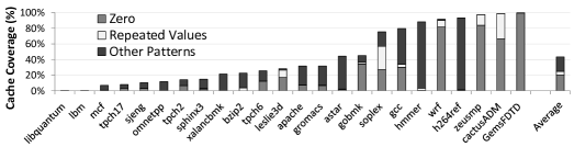
In this work, we make two observations. First, we find that the above described patterns are widely present in many applications (SPEC CPU benchmark suites, and some server applications, e.g., Apache, TPC-H). Figure 3.1 plots the percentage of cache lines that can be compressed using different patterns.111The methodology used in this and other experiments is described in Section 3.7. We use a 2MB L2 cache unless otherwise stated. As the figure shows, on average, 43% of all cache lines belonging to these applications can be compressed. This shows that there is significant opportunity to exploit data compression to improve on-chip cache performance.
Second, and more importantly, we observe that all the above commonly occurring patterns fall under the general notion of low dynamic range – a set of values where the differences between the values is much smaller than the values themselves. Unlike prior work, which has attempted to exploit each of these special patterns individually for cache compression [10, 256] or main memory compression [57, 246], our goal is to exploit the general case of values with low dynamic range to build a simple yet effective compression technique.
Summary comparison: Our resulting mechanism, base-delta-immediate (BI) compression, strikes a sweet-spot in the tradeoff between decompression latency (Decomp. Lat.), hardware complexity of the implementation (Complex.), and compression ratio (C. Ratio), as shown in Table 3.1. The table qualitatively compares BI with three state-of-the-art mechanisms: ZCA [54], which does zero-value compression, Frequent Value Compression (FVC) [256], and Frequent Pattern Compression (FPC) [10]. (These mechanisms are described in detail in Section 3.6.) It also summarizes which data patterns (zeros, repeated values, narrow values, and other low dynamic range patterns) are compressible with each mechanism. For modest complexity, BI is the only design to achieve both low decompression latency and high compression ratio.
3.3 Base + Delta Encoding: Basic Idea
We propose a new cache compression mechanism, Base+Delta (B) compression, which unlike prior work [10, 54, 256], looks for compression opportunities at a cache line granularity – i.e., B either compresses the entire cache line or stores the entire cache line in uncompressed format. The key observation behind B is that many cache lines contain data with low dynamic range. As a result, the differences between the words within such a cache line can be represented using fewer bytes than required to represent the words themselves. We exploit this observation to represent a cache line with low dynamic range using a common base and an array of deltas (differences between values within the cache line and the common base). Since the deltas require fewer bytes than the values themselves, the combined size of the base and the array of deltas can be much smaller than the size of the original uncompressed cache line.
The fact that some values can be represented in base+delta form has been observed by others, and used for different purposes: e.g. texture compression in GPUs [227] and also to save bandwidth on CPU buses by transferring only deltas from a common base [64]. To our knowledge, no previous work examined the use of base+delta representation to improve on-chip cache utilization in a general-purpose processor.
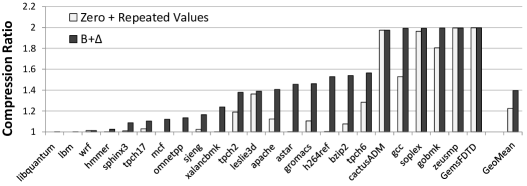
To evaluate the applicability of the B compression technique for a large number of applications, we conducted a study that compares the effective compression ratio (i.e., effective cache size increase, see Section 3.7 for a full definition) of B against a simple technique that compresses two common data patterns (zeros and repeated values222Zero compression compresses an all-zero cache line into a bit that just indicates that the cache line is all-zero. Repeated value compression checks if a cache line has the same 1/2/4/8 byte value repeated. If so, it compresses the cache line to the corresponding value.). Figure 3.2 shows the results of this study for a 2MB L2 cache with 64-byte cache lines for applications in the SPEC CPU2006 benchmark suite, database and web-server workloads (see Section 3.7 for methodology details). We assume a design where a compression scheme can store up to twice as many tags for compressed cache lines than the number of cache lines stored in the uncompressed baseline cache (Section 3.5 describes a practical mechanism that achieves this by using twice the number of tags).333This assumption of twice as many tags as the baseline is true for all compressed cache designs, except in Section 3.8.3. As the figure shows, for a number of applications, B provides significantly higher compression ratio (1.4X on average) than using the simple compression technique. However, there are some benchmarks for which B provides very little or no benefit (e.g., libquantum, lbm, and mcf). We will address this problem with a new compression technique called BI in Section 3.4. We first provide examples from real applications to show why B works.
3.3.1 Why Does B Work?
B works because of: (1) regularity in the way data is allocated in the memory (similar data values and types grouped together), and (2) low dynamic range of cache/memory data. The first reason is typically true due to the common usage of arrays to represent large pieces of data in applications. The second reason is usually caused either by the nature of computation, e.g., sparse matrices or streaming applications; or by inefficiency (over-provisioning) of data types used by many applications, e.g., 4-byte integer type used to represent values that usually need only 1 byte. We have carefully examined different common data patterns in applications that lead to B representation and summarize our observations in two examples.
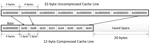
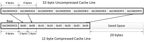
Figures 3.4 and 3.4 show the compression of two 32-byte444We use 32-byte cache lines in our examples to save space. 64-byte cache lines were used in all evaluations (see Section 3.7). cache lines from the applications h264ref and perlbench using B. The first example from h264ref shows a cache line with a set of narrow values stored as 4-byte integers. As Figure 3.4 indicates, in this case, the cache line can be represented using a single 4-byte base value, , and an array of eight 1-byte differences. As a result, the entire cache line data can be represented using 12 bytes instead of 32 bytes, saving 20 bytes of the originally used space. Figure 3.4 shows a similar phenomenon where nearby pointers are stored in the same cache line for the perlbench application.
We now describe more precisely the compression and decompression algorithms that lay at the heart of the B compression mechanism.
3.3.2 Compression Algorithm
The B compression algorithm views a cache line as a set of fixed-size values i.e., 8 8-byte, 16 4-byte, or 32 2-byte values for a 64-byte cache line. It then determines if the set of values can be represented in a more compact form as a base value with a set of differences from the base value. For analysis, let us assume that the cache line size is bytes, the size of each value in the set is bytes and the set of values to be compressed is , where . The goal of the compression algorithm is to determine the value of the base, and the size of values in the set, , that provide maximum compressibility. Once and are determined, the output of the compression algorithm is , where .
Observation 1: The cache line is compressible only
if
,
where is the smallest number of bytes that is
needed to store .
In other words, for the cache line to be compressible, the number of bytes required to represent the differences must be strictly less than the number of bytes required to represent the values themselves.
Observation 2: To determine the value of , either the value of or needs to be found.
The reasoning, where / are the maximum and minimum values in the cache line, is based on the observation that the values in the cache line are bounded by and . And, hence, the optimum value for should be between and . In fact, the optimum can be reached only for , , or exactly in between them. Any other value of can only increase the number of bytes required to represent the differences.
Given a cache line, the optimal version of the B compression algorithm needs to determine two parameters: (1) , the size of each value in , and (2) , the optimum base value that gives the best possible compression for the chosen value of .
Determining . Note that the value of determines how the cache line is viewed by the compression algorithm – i.e., it defines the set of values that are used for compression. Choosing a single value of for all cache lines will significantly reduce the opportunity of compression. To understand why this is the case, consider two cache lines, one representing a table of 4-byte pointers pointing to some memory region (similar to Figure 3.4) and the other representing an array of narrow values stored as 2-byte integers. For the first cache line, the likely best value of is , as dividing the cache line into a set of of values with a different might lead to an increase in dynamic range and reduce the possibility of compression. Similarly, the likely best value of for the second cache line is .
Therefore, to increase the opportunity for compression by catering to multiple patterns, our compression algorithm attempts to compress a cache line using three different potential values of simultaneously: , , and . The cache line is then compressed using the value that provides the maximum compression rate or not compressed at all.555 We restrict our search to these three values as almost all basic data types supported by various programming languages have one of these three sizes.
Determining . For each possible value of {, , }, the cache line is split into values of size and the best value for the base, can be determined using Observation 2. However, computing in this manner requires computing the maximum or the minimum of the set of values, which adds logic complexity and significantly increases the latency of compression.
To avoid compression latency increase and reduce hardware complexity, we decide to use the first value from the set of values as an approximation for the . For a compressible cache line with a low dynamic range, we find that choosing the first value as the base instead of computing the optimum base value reduces the average compression ratio only by 0.4%.
3.3.3 Decompression Algorithm
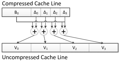
To decompress a compressed cache line, the B decompression algorithm needs to take the base value and an array of differences , and generate the corresponding set of values . The value is simply given by . As a result, the values in the cache line can be computed in parallel using a SIMD-style vector adder. Consequently, the entire cache line can be decompressed in the amount of time it takes to do an integer vector addition, using a set of simple adders.
3.4 BI Compression
3.4.1 Why Could Multiple Bases Help?
Although B proves to be generally applicable for many applications, it is clear that not every cache line can be represented in this form, and, as a result, some benchmarks do not have a high compression ratio, e.g., mcf. One common reason why this happens is that some of these applications can mix data of different types in the same cache line, e.g., structures of pointers and 1-byte integers. This suggests that if we apply B with multiple bases, we can improve compressibility for some of these applications.
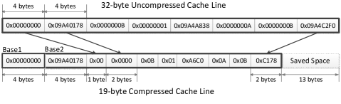
Figure 3.5 shows a 32-byte cache line from mcf that is not compressible with a single base using B, because there is no single base value that effectively compresses this cache line. At the same time, it is clear that if we use two bases, this cache line can be easily compressed using a similar compression technique as in the B algorithm with one base. As a result, the entire cache line data can be represented using 19 bytes: 8 bytes for two bases (0x00000000 and 0x09A40178), 5 bytes for five 1-byte deltas from the first base, and 6 bytes for three 2-byte deltas from the second base. This effectively saves 13 bytes of the 32-byte line.
As we can see, multiple bases can help compress more cache lines, but, unfortunately, more bases can increase overhead (due to storage of the bases), and hence decrease effective compression ratio that can be achieved with one base. So, it is natural to ask how many bases are optimal for B compression?
In order to answer this question, we conduct an experiment where we evaluate the effective compression ratio with different numbers of bases (selected suboptimally using a greedy algorithm). Figure 3.6 shows the results of this experiment. The “0” base bar corresponds to a mechanism that compresses only simple patterns (zero and repeated values). These patterns are simple to compress and common enough, so we can handle them easily and efficiently without using B, e.g., a cache line of only zeros compressed to just one byte for any number of bases. We assume this optimization for all bars in Figure 3.6.666If we do not assume this optimization, compression with multiple bases will have very low compression ratio for such common simple patterns.
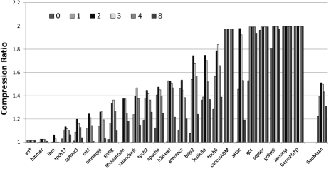
Results in Figure 3.6 show that the empirically optimal number of bases in terms of effective compression ratio is 2, with some benchmarks having optimums also at one or three bases. The key conclusion is that B with two bases significantly outperforms B with one base (compression ratio of 1.51 vs. 1.40 on average), suggesting that it is worth considering for implementation. Note that having more than two bases does not provide additional improvement in compression ratio for these workloads, because the overhead of storing more bases is higher than the benefit of compressing more cache lines.
Unfortunately, B with two bases has a serious drawback: the necessity of finding a second base. The search for a second arbitrary base value (even a sub-optimal one) can add significant complexity to the compression hardware. This opens the question of how to find two base values efficiently. We next propose a mechanism that can get the benefit of compression with two bases with minimal complexity.
3.4.2 BI: Refining B with Two Bases and Minimal Complexity
Results from Section 3.4.1 suggest that the optimal (on average) number of bases to use is two, but having an additional base has the significant shortcoming described above. We observe that setting the second base to zero gains most of the benefit of having an arbitrary second base value. Why is this the case?
Most of the time when data of different types are mixed in the same cache line, the cause is an aggregate data type: e.g., a structure (struct in C). In many cases, this leads to the mixing of wide values with low dynamic range (e.g., pointers) with narrow values (e.g., small integers). A first arbitrary base helps to compress wide values with low dynamic range using base+delta encoding, while a second zero base is efficient enough to compress narrow values separately from wide values. Based on this observation, we refine the idea of B by adding an additional implicit base that is always set to zero. We call this refinement Base-Delta-Immediate or BI compression.
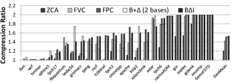
There is a tradeoff involved in using BI instead of B with two arbitrary bases. BI uses an implicit zero base as the second base, and, hence, it has less storage overhead, which means potentially higher average compression ratio for cache lines that are compressible with both techniques. B with two general bases uses more storage to store an arbitrary second base value, but can compress more cache lines because the base can be any value. As such, the compression ratio can potentially be better with either mechanism, depending on the compressibility pattern of cache lines. In order to evaluate this tradeoff, we compare in Figure 3.7 the effective compression ratio of BI, B with two arbitrary bases, and three prior approaches: ZCA [54] (zero-based compression), FVC [256], and FPC [10].777All mechanisms are covered in detail in Section 3.6. We provide a comparison of their compression ratios here to give a demonstration of BDI’s relative effectiveness and to justify it as a viable compression mechanism.
Although there are cases where B with two bases is better — e.g., leslie3d and bzip2 — on average, BI performs slightly better than B in terms of compression ratio (1.53 vs. 1.51). We can also see that both mechanisms are better than the previously proposed FVC mechanism [256], and competitive in terms of compression ratio with a more complex FPC compression mechanism. Taking into an account that B with two bases is also a more complex mechanism than BI, we conclude that our cache compression design should be based on the refined idea of BI.
Now we will describe the design and operation of a cache that implements our BI compression algorithm.
3.5 BI: Design and Operation
3.5.1 Design
Compression and Decompression. We now describe the detailed design of the corresponding compression and decompression logic.888For simplicity, we start with presenting the compression and decompression logic for B. Compression for BI requires one more step, where elements are checked to be compressed with zero base; decompression logic only requires additional selector logic to decide which base should be used in the addition. We describe the differences between BI and B designs later in this section. The compression logic consists of eight distinct compressor units: six units for different base sizes (8, 4 and 2 bytes) and sizes (4, 2 and 1 bytes), and two units for zero and repeated value compression (Figure 3.8). Every compressor unit takes a cache line as an input, and outputs whether or not this cache line can be compressed with this unit. If it can be, the unit outputs the compressed cache line. The compressor selection logic is used to determine a set of compressor units that can compress this cache line. If multiple compression options are available for the cache line (e.g., 8-byte base 1-byte and zero compression), the selection logic chooses the one with the smallest compressed cache line size. Note that all potential compressed sizes are known statically and described in Table 3.2. All compressor units can operate in parallel.
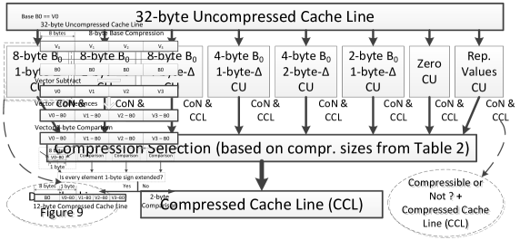
Figure 3.9 describes the organization of the 8-byte-base 1-byte- compressor unit for a 32-byte cache line. The compressor “views” this cache line as a set of four 8-byte elements (, , , ), and in the first step, computes the difference between the base element and all other elements. Recall that the base () is set to the first value (), as we describe in Section 3.3. The resulting difference values () are then checked to see whether their first 7 bytes are all zeros or ones (1-byte sign extension check). If so, the resulting cache line can be stored as the base value and the set of differences , where each requires only 1 byte. The compressed cache line size in this case is 12 bytes instead of the original 32 bytes. If the 1-byte sign extension check returns false (i.e., at least one cannot be represented using 1 byte), then the compressor unit cannot compress this cache line. The organization of all other compressor units is similar. This compression design can be potentially optimized, especially if hardware complexity is more critical than latency, e.g., all 8-byte-base value compression units can be united into one to avoid partial logic duplication.
| Name | Base | Size | Enc. | Name | Base | Size | Enc. | ||
|---|---|---|---|---|---|---|---|---|---|
| Zeros | 1 | 0 | 1/1 | 0000 | Rep.Values | 8 | 0 | 8/8 | 0001 |
| Base8-1 | 8 | 1 | 12/16 | 0010 | Base8-2 | 8 | 2 | 16/24 | 0011 |
| Base8-4 | 8 | 4 | 24/40 | 0100 | Base4-1 | 4 | 1 | 12/20 | 0101 |
| Base4-2 | 4 | 2 | 20/36 | 0110 | Base2-1 | 2 | 1 | 18/34 | 0111 |
| NoCompr. | N/A | N/A | 32/64 | 1111 |
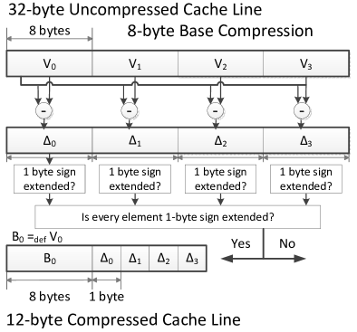
Figure 3.10 shows the latency-critical decompression logic. Its organization is simple: for a compressed cache line that consists of a base value and a set of differences , only additions of the base to the differences are performed to obtain the uncompressed cache line. Such decompression will take as long as the latency of an adder, and allows the BI cache to perform decompression very quickly.
BI Cache Organization. In order to obtain the benefits of compression, the conventional cache design requires certain changes. Cache compression potentially allows more cache lines to be stored in the same data storage than a conventional uncompressed cache. But, in order to access these additional compressed cache lines, we need a way to address them. One way to achieve this is to have more tags [10], e.g., twice as many,999We describe an implementation with the number of tags doubled and evaluate sensitivity to the number of tags in Section 3.8. than the number we have in a conventional cache of the same size and associativity. We can then use these additional tags as pointers to more data elements in the corresponding data storage.
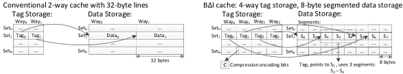
Figure 3.11 shows the required changes in the cache design. The conventional 2-way cache with 32-byte cache lines (shown on the top) has a tag store with two tags per set, and a data store with two 32-byte cache lines per set. Every tag directly maps to the corresponding piece of the data storage. In the BI design (at the bottom), we have twice as many tags (four in this example), and every tag also has 4 additional bits to represent whether or not the line is compressed, and if it is, what compression type is used (see “Encoding” in Table 3.2). The data storage remains the same in size as before (232 = 64 bytes), but it is separated into smaller fixed-size segments (e.g., 8 bytes in size in Figure 3.11). Every tag stores the starting segment (e.g., stores segment ) and the encoding for the cache block. By knowing the encoding we can easily know the number of segments used by the cache block.
Storage Cost Analysis. This cache organization potentially allows storing twice as many cache lines in the same data storage, because the number of tags in a set is doubled. As a result, it requires modest increase in the tag store size (similar to some other designs [11, 72, 195]. We analyze the storage overhead in terms of raw additional bits in Table 3.3 for a baseline 16-way 2MB cache. We have also used CACTI 5.3 [229] to estimate the additional latency and area cost of our proposed cache organization, using parameters for the 32nm technology node. Cache access latency increases by 1-2 cycles (depending on cache size) for a 4GHz processor. On-chip cache area increases by 2.3%, but this increase is small compared to the 137% increase in area, which occurs if we double both the tag store and the data store size (by doubling the associativity).101010As we show in Section 3.8, BI with our proposed cache organization achieves performance that is within 1-2% of a cache that has double the tag and data store size.
| Baseline | BI | |
| Size of tag-store entry | 21 bits | 32 bits (+4–encoding, +7–segment pointer) |
| Size of data-store entry | 512 bits | 512 bits |
| Number of tag-store entries | 32768 | 65536 |
| Number of data-store entries | 32768 | 32768 |
| Tag-store size | 84kB | 256kB |
| Total (data-store+tag-store) size | 2132kB | 2294kB |
Cache Eviction Policy. In a compressed cache, there are two cases under which multiple cache lines may need to be evicted because evicting a single cache line (i.e., the LRU one in a cache that uses the LRU replacement policy) may not create enough space for the incoming or modified cache line. First, when a new cache line (compressed or uncompressed) is inserted into the cache. Second, when a cache line already in the cache is modified such that its new size is larger than its old size. In both cases, we propose to use a slightly modified version of the LRU replacement policy wherein the cache evicts multiple LRU cache lines to create enough space for the incoming or modified cache line.111111On average, 5.2% of all insertions or writebacks into the cache resulted in the eviction of multiple cache lines in our workloads. such a policy can increase the latency of eviction, it has negligible effect on performance as evictions are off the critical path of execution. Note that more effective replacement policies that take into account compressed cache line sizes are possible – e.g., a policy that does not evict a zero cache line unless there is a need for space in the tag store. We leave the study of such policies for future work.
BI Design Specifics. So far, we described the common part in the designs of both B and BI. However, there are some specific differences between these two designs.
First, BI compression happens (off the critical path) in two steps (vs. only one step for B). For a fixed size, Step 1 attempts to compress all elements using an implicit base of zero. Step 2 tries to compress those elements that were not compressed in Step 1. The first uncompressible element of Step 1 is chosen as the base for Step 2. The compression step stores a bit mask, 1-bit per element indicating whether or not the corresponding base is zero. Note that we keep the size of (1, 2, or 4 bytes) the same for both bases.
Second, BI decompression is implemented as a masked addition of the base (chosen in Step 2) to the array of differences. The elements to which the base is added depends on the bit-mask stored in the compression step.
3.5.2 Operation
We propose using our BI design at cache levels higher than L1 (e.g., L2 and L3). While it is possible to compress data in the L1 cache [256], doing so will increase the critical path of latency-sensitive L1 cache hits. This can result in significant performance degradation for applications that do not benefit from compression.
We now describe how a BI cache fits into a system with a 2-level cache hierarchy (L1, L2 and main memory) with the L2 cache compressed using BI – note that the only changes are to the L2 cache. We assume all caches use the writeback policy. There are four scenarios related to the compressed L2 cache operation: 1) an L2 cache hit, 2) an L2 cache miss, 3) a writeback from L1 to L2, and 4) a writeback from L2 to memory.
First, on an L2 hit, the corresponding cache line is sent to the L1 cache. If the line is compressed, it is first decompressed before it is sent to the L1 cache. Second, on an L2 miss, the corresponding cache line is brought from memory and is sent to the L1 cache. In this case, the line is also compressed and inserted into the L2 cache. Third, when a line is written back from L1 to L2, it is first compressed. If an old copy of the line is already present in the L2 cache, the old (stale) copy is invalidated. The new compressed cache line is then inserted into the L2 cache. Fourth, when a line is written back from L2 cache to memory, it is decompressed before it is sent to the memory controller. In both second and third scenarios, potentially multiple cache lines might be evicted from the L2 cache based on the cache eviction policy described in Section 3.5.1.
3.6 Related Work
Multiple previous works investigated the possibility of using compression for on-chip caches [264, 10, 54, 93, 72, 38] and/or memory [246, 3, 57]. All proposed designs have different tradeoffs between compression ratio, decompression/compression latency and hardware complexity. The spectrum of proposed algorithms ranges from general-purpose compression schemes e.g., the Lempel-Ziv algorithm [268], to specific pattern-based schemes, e.g., zero values [54, 93] and frequent values [256].
The fundamental difference between BI and previous cache compression mechanisms is that whereas prior techniques compress data at word granularity – i.e., each word within a cache line is compressed separately, BI compresses data at cache-line granularity – i.e., all the words within a cache line are compressed using the same encoding or all the words within a cache line are stored uncompressed. As a result, BI provides two major advantages. First, the decompression of all words in the same cache line can be performed in parallel (using a masked vector addition), since the starting point of each word is known in the compressed cache line. In contrast, compressing each word within a cache line separately, as in prior works, typically serializes decompression as different words can be compressed to different sizes, making the starting point of each word in the compressed cache line dependent on the previous word. Second, BI exploits correlation across words within a cache line, which can lead to a better compression ratio – e.g., when cache line consists of an array of pointers. Prior works do not exploit this correlation as they compress words individually. As already summarized in Table 1, different prior works suffer from one or more of the following shortcomings, which BI alleviates: 1) high decompression latency, 2) low effective compression ratio, and 3) high hardware complexity. We now describe the prior designs in more detail.
3.6.1 Zero-based Designs
Dusser et al. [54] propose Zero-Content Augmented (ZCA) cache design where a conventional cache is augmented with a specialized cache to represent zero cache lines. Decompression and compression latencies as well as hardware complexity for the ZCA cache design are low. However, only applications that operate on a large number of zero cache lines can benefit from this design. In our experiments, only 6 out of 24 applications have enough zero data to benefit from ZCA (Figure 3.7), leading to relatively small performance improvements (as we show in Section 3.8).
Islam and Stenström [93] observe that 18% of the dynamic loads actually access zero data, and propose a cache design called Zero-Value Canceling where these loads can be serviced faster. Again, this can improve performance only for applications with substantial amounts of zero data. Our proposal is more general than these designs that are based only on zero values.
3.6.2 Frequent Value Compression
Zhang et al. [264] observe that a majority of values read or written by memory operations come from a small set of frequently occurring values. Based on this observation, they propose a compression technique [256] that encodes frequent values present in cache lines with fewer bits. They apply this technique to a direct-mapped L1 cache wherein each entry in the cache can store either one uncompressed line or two compressed lines.
Frequent value compression (FVC) has three major drawbacks. First, since FVC can only compress frequent values, it cannot exploit other commonly found patterns, e.g., narrow values or stride patterns in application data. As a result, it does not provide a high degree of compression for most applications as shown in Section 3.8. Second, FVC compresses only the frequent values, while other values stay uncompressed. Decompression of such a cache line requires sequential processing of every element (because the beginning of the next element can be determined only after the previous element is processed), significantly increasing the latency of decompression, which is undesirable. Third, the proposed mechanism requires profiling to identify the frequent values within an application. Our quantitative results in Section 3.8 shows that BI outperforms FVC due to these reasons.
3.6.3 Pattern-Based Compression Techniques
Alameldeen and Wood [10] propose frequent pattern compression (FPC) that exploits the observation that a majority of words fall under one of a few compressible patterns, e.g., if the upper 16 bits of a 32-bit word are all zeros or are all ones, all bytes in a 4-byte word are the same. FPC defines a set of these patterns [11] and then uses them to encode applicable words with fewer bits of data. For compressing a cache line, FPC first divides the cache line into 32-bit words and checks if each word falls under one of seven frequently occurring patterns. Each compressed cache line contains the pattern encoding for all the words within the cache line followed by the additional data required to decompress each word.
The same authors propose a compressed cache design [10] based on FPC which allows the cache to store two times more compressed lines than uncompressed lines, effectively doubling the cache size when all lines are compressed. For this purpose, they maintain twice as many tag entries as there are data entries. Similar to frequent value compression, frequent pattern compression also requires serial decompression of the cache line, because every word can be compressed or decompressed. To mitigate the decompression latency of FPC, the authors design a five-cycle decompression pipeline [11]. They also propose an adaptive scheme which avoids compressing data if the decompression latency nullifies the benefits of compression.
Chen et al. [38] propose a pattern-based compression mechanism (called C-Pack) with several new features: (1) multiple cache lines can be compressed into one, (2) multiple words can be compressed in parallel; but parallel decompression is not possible. Although the C-Pack design is more practical than FPC, it still has a high decompression latency (8 cycles due to serial decompression), and its average compression ratio is lower than that of FPC.
3.6.4 Follow-up Work
Publication of this work [185] inspired several new proposals for hardware-oriented compression algorithms [16, 15, 168, 117], and new compressed cache designs [203, 200, 202]. Most of these works aim for higher compression ratios, but this happens at the cost of much higher compression/decompression latency. This is why some of these works [168, 117] are proposed in the context of modern GPUs that are much more tolerant to increase in memory latency.
3.7 Evaluation Methodology
We use an in-house, event-driven 32-bit x86 simulator whose front-end is based on Simics [154]. All configurations have either a two- or three-level cache hierarchy, with private L1D caches. Major simulation parameters are provided in Table 3.4. All caches uniformly use a 64B cache block size and LRU policy for replacement. All cache latencies were determined using CACTI [229] (assuming a 4GHz frequency), and provided in Table 3.5. We also checked that these latencies match the existing last level cache implementations from Intel and AMD, when properly scaled to the corresponding frequency.121212Intel Xeon X5570 (Nehalem) 2.993GHz, 8MB L3 - 35 cycles [160]; AMD Opteron 2.8GHz, 1MB L2 - 13 cycles [37]. For evaluations, we use benchmarks from the SPEC CPU2006 suite [217], three TPC-H queries [232], and an Apache web server (shown in Table 3.6, whose detailed description is in Section 3.8). All results are collected by running a representative portion of the benchmarks for 1 billion instructions.
| Processor | 1–4 cores, 4GHz, x86 in-order |
|---|---|
| L1-D cache | 32kB, 64B cache-line, 2-way, 1 cycle |
| L2 caches | 0.5–16 MB, 64B cache-line, 16-way |
| L3 caches | 2–16 MB, 64B cache-line, 16-way |
| Memory | 300 cycle latency |
| Size | Latency | Size | Latency | Size | Latency |
|---|---|---|---|---|---|
| 512kB | 15 | 1MB | 21 | 2MB | 27 |
| 4MB | 34 | 8MB | 41 | 16MB | 48 |
Metrics. We measure performance of our benchmarks using IPC (instruction per cycle), effective compression ratio (effective cache size increase, e.g., 1.5 for 2MB cache means effective size of 3MB), and MPKI (misses per kilo instruction). For multi-programmed workloads we use the weighted speedup [216, 61] as the performance metric: ( ). For bandwidth consumption we use BPKI (bytes transferred over bus per thousand instructions [218]).
Effective compression ratio for all mechanisms is computed without meta-data overhead. We add all meta-data to the tag storage, e.g., for BI, we add four bits to encode the compression scheme, and a bit mask to differentiate between two bases. We include these in the tag overhead, which was evaluated in Section 3.5. Our comparisons are fair, because we do not include this overhead in compression ratios of previous works we compare to. In fact, the meta-data overhead is higher for FPC (3 bits for each word).
We conducted a study to see applications’ performance sensitivity to the increased L2 cache size (from 512kB to 16 MB). Our results show that there are benchmarks that are almost insensitive (IPC improvement less than 5% with 32x increase in cache size) to the size of the L2 cache: dealII, povray, calculix, gamess, namd, milc, and perlbench. This typically means that their working sets mostly fit into the L1D cache, leaving almost no potential for any L2/L3/memory optimization. Therefore, we do not present data for these applications, although we verified that our mechanism does not affect their performance.
Parameters of Evaluated Schemes. For FPC, we used a decompression latency of 5 cycles, and a segment size of 1 byte (as for BI) to get the highest compression ratio as described in [11]. For FVC, we used static profiling for 100k instructions to find the 7 most frequent values as described in [256], and a decompression latency of 5 cycles. For ZCA and BI, we used a decompression latency of 1 cycle.
We also evaluated BI with higher decompression latencies (2-5 cycles). BI continues to provide better performance, because for most applications it provides a better overall compression ratio than prior mechanisms. When decompression latency of BI increases from 1 to 5 cycles, performance degrades by 0.74%.
Internal Fragmentation. In our simulations, we assumed that before every insertion, we can shift segments properly to avoid fragmentation (implementable, but might be inefficient). We believe this is reasonable, because insertion happens off the critical path of the execution. Previous work [10] adopted this assumption, and we treated all schemes equally in our evaluation. Several more recent works [203, 200, 202] (after this work was published) looked at more efficient ways of handling fragmentation.
| Cat. | Name | Comp. Ratio | Sens. | Name | Comp. Ratio | Sens. | Name | Comp. Ratio | Sens. |
| LCLS | gromacs | 1.43 / L | L | hmmer | 1.03 / L | L | lbm | 1.00 / L | L |
| leslie3d | 1.41 / L | L | sphinx | 1.10 / L | L | tpch17 | 1.18 / L | L | |
| libquantum | 1.25 / L | L | wrf | 1.01 / L | L | ||||
| HCLS | apache | 1.60 / H | L | zeusmp | 1.99 / H | L | gcc | 1.99 / H | L |
| gobmk | 1.99 / H | L | sjeng | 1.50 / H | L | tpch2 | 1.54 / H | L | |
| tpch6 | 1.93 / H | L | GemsFDTD | 1.99 / H | L | cactusADM | 1.97 / H | L | |
| HCHS | astar | 1.74 / H | H | bzip2 | 1.60 / H | H | mcf | 1.52 / H | H |
| omnetpp | 1.58 / H | H | soplex | 1.99 / H | H | h264ref | 1.52 / H | H | |
| xalancbmk | 1.61 / H | H |
3.8 Results & Analysis
3.8.1 Single-core Results
Figure 3.14(a) shows the performance improvement of our proposed BI design over the baseline cache design for various cache sizes, normalized to the performance of a 512KB baseline design. The results are averaged across all benchmarks. Figure 3.14(b) plots the corresponding results for MPKI also normalized to a 512KB baseline design. Several observations are in-order. First, the BI cache significantly outperforms the baseline cache for all cache sizes. By storing cache lines in compressed form, the BI cache is able to effectively store more cache lines and thereby significantly reduce the cache miss rate (as shown in Figure 3.14(b)). Second, in most cases, BI achieves the performance improvement of doubling the cache size. In fact, the 2MB BI cache performs better than the 4MB baseline cache. This is because, BI increases the effective cache size without significantly increasing the access latency of the data storage. Third, the performance improvement of BI cache decreases with increasing cache size. This is expected because, as cache size increases, the working set of more benchmarks start fitting into the cache. Therefore, storing the cache lines in compressed format has increasingly less benefit. Based on our results, we conclude that BI is an effective compression mechanism to significantly improve single-core performance, and can provide the benefits of doubling the cache size without incurring the area and latency penalties associated with a cache of twice the size.
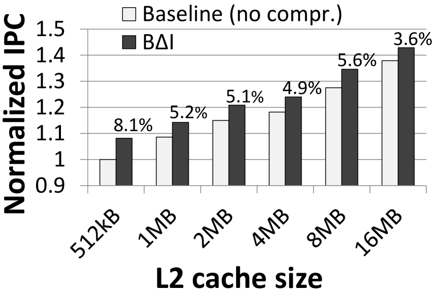
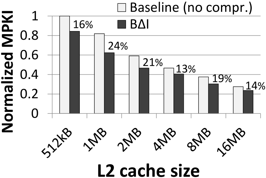
3.8.2 Multi-core Results
When the working set of an application fits into the cache, the application will not benefit significantly from compression even though its data might have high redundancy. However, when such an application is running concurrently with another cache-sensitive application in a multi-core system, storing its cache lines in compressed format will create additional cache space for storing the data of the cache-sensitive application, potentially leading to significant overall performance improvement.
To study this effect, we classify our benchmarks into four categories based on their compressibility using BI (low (LC) or high (HC)) and cache sensitivity (low (LS) or high (HS)). Table 3.6 shows the sensitivity and compressibility of different benchmarks along with the criteria used for classification. None of the benchmarks used in our evaluation fall into the low-compressibility high-sensitivity (LCHS) category. We generate six different categories of 2-core workloads (20 in each category) by randomly choosing benchmarks with different characteristics (LCLS, HCLS and HCHS).
Figure 3.15 shows the performance improvement provided by four different compression schemes, namely, ZCA, FVC, FPC, and BI, over a 2MB baseline cache design for different workload categories. We draw three major conclusions.
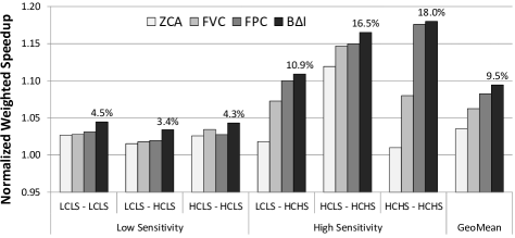
First, BI outperforms all prior approaches for all workload categories. Overall, BI improves system performance by 9.5% compared to the baseline cache design.
Second, as we mentioned in the beginning of this section, even though an application with highly compressible data may not itself benefit from compression (HCLS), it can enable opportunities for performance improvement for the co-running application. This effect is clearly visible in the figure. When at least one benchmark is sensitive to cache space, the performance improvement of BI increases with increasing compressibility of the co-running benchmark (as observed by examining the bars labeled as High Sensitivity). BI provides the highest improvement (18%) when both benchmarks in a workload are highly compressible and highly sensitive to cache space (HCHS-HCHS). As the figure shows, the performance improvement is not as significant when neither benchmark is sensitive to cache space irrespective of their compressibility (as observed by examining the bars labeled Low Sensitivity).
Third, although FPC provides a degree of compression similar to BI for most benchmarks (as we showed in Section 3.4.2, Figure 3.7) its performance improvement is lower than BI for all workload categories. This is because FPC has a more complex decompression algorithm with higher decompression latency compared to BI. On the other hand, for high sensitivity workloads, neither ZCA nor FVC is as competitive as FPC or BI in the HCLS-HCHS category. This is because both ZCA and FVC have a significantly lower degree of compression compared to BI. However, a number of benchmarks in the HCLS category (cactusADM, gcc, gobmk, zeusmp, and GemsFDTD) have high occurrences of zero in their data. Therefore, ZCA and FVC are able to compress most of the cache lines of these benchmarks, thereby creating additional space for the co-running HCHS application.
We conducted a similar experiment with 100 4-core workloads with different compressibility and sensitivity characteristics. We observed trends similar to the 2-core results presented above. On average, BI improves performance by 11.2% for the 4-core workloads and it outperforms all previous techniques. We conclude that BI, with its high compressibility and low decompression latency, outperforms other state-of-the-art compression techniques for both 2-core and 4-core workloads, likely making it a more competitive candidate for adoption in modern multi-core processors.
We summarize BI performance improvement against the baseline 2MB L2 cache (without compression) and other mechanisms in Table 3.7.
| Cores | No Compression | ZCA | FVC | FPC |
|---|---|---|---|---|
| 1 | 5.1% | 4.1% | 2.1% | 1.0% |
| 2 | 9.5% | 5.7% | 3.1% | 1.2% |
| 4 | 11.2% | 5.6% | 3.2% | 1.3% |
3.8.3 Effect on Cache Capacity
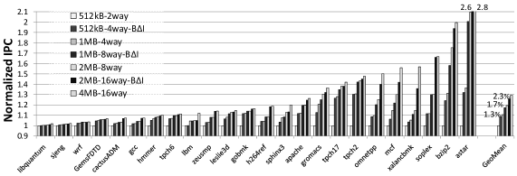
Our proposed BI cache design aims to provide the benefits of increasing the cache size while not incurring the increased latency of a larger data storage. To decouple the benefits of compression using BI from the benefits of reduced latency compared to a larger cache, we perform the following study. We compare the performance of the baseline cache design and the BI cache design by progressively doubling the cache size by doubling the cache associativity. We fix the latency of accessing all caches.
Figure 3.16 shows the results of this experiment. With the same access latency for all caches, we expect the performance of the BI cache (with twice the number of tags as the baseline) to be strictly between the baseline cache of the same size (lower limit) and the baseline cache of double the size (upper limit, also reflected in our results). However, with its high degree of compression, the BI cache’s performance comes close to the performance of the twice as-large baseline cache design for most benchmarks (e.g., h264ref and zeusmp). On average, the performance improvement due to the BI cache is within 1.3% – 2.3% of the improvement provided by a twice as-large baseline cache. We conclude that our BI implementation (with twice the number of tags as the baseline) achieves performance improvement close to its upper bound potential performance of a cache twice the size of the baseline.
For an application with highly compressible data, the compression ratio of the BI cache is limited by the number of additional tags used in its design. Figure 3.17 shows the effect of varying the number of tags (from 2 to 64 the number of tags in the baseline cache) on compression ratio for a 2MB cache. As the figure shows, for most benchmarks, except soplex, cactusADM, zeusmp, and GemsFDTD, having more than twice as many tags as the baseline cache does not improve the compression ratio. The improved compression ratio for the four benchmarks is primarily due to the large number of zeros and repeated values present in their data. At the same time, having more tags does not benefit a majority of the benchmarks and also incurs higher storage cost and access latency. Therefore, we conclude that these improvements likely do not justify the use of more than 2X the tags in the BI cache design compared to the baseline cache.
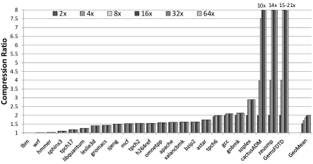
3.8.4 Effect on Bandwidth
In a system with a 3-level cache hierarchy, where both the L2 and the L3 caches store cache lines in compressed format, there is an opportunity to compress the traffic between the two caches. This has two benefits: (1) it can lead to reduced latency of communication between the two caches, and hence, improved system performance, and (2) it can lower the dynamic power consumption of the processor as it communicates less data between the two caches [103]. Figure 3.18 shows the reduction in L2-L3 bandwidth (in terms of bytes per kilo instruction) due to BI compression. We observe that the potential bandwidth reduction with BI is as high as 53X (for GemsFDTD), and 2.31X on average. We conclude that BI can not only increase the effective cache size, but it can also significantly decrease the on-chip traffic.
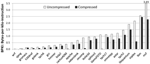
3.8.5 Detailed Comparison with Prior Work
To compare the performance of BI against state-of-the-art cache compression techniques, we conducted a set of studies and evaluated IPC, MPKI, and effective compression ratio (Figure 3.7) for single core workloads, and weighted speedup (Figure 3.15) for two- and four-core workloads.
Figure 3.19 shows the improvement in IPC using different compression mechanisms over a 2MB baseline cache in a single-core system. As the figure shows, BI outperforms all prior approaches for most of the benchmarks. For benchmarks that do not benefit from compression (e.g, leslie3d, GemsFDTD, and hmmer), all compression schemes degrade performance compared to the baseline. However, BI has the lowest performance degradation with its low 1-cycle decompression latency, and never degrades performance by more than 1%. On the other hand, FVC and FPC degrade performance by as much as 3.1% due to their relatively high 5-cycle decompression latency. We also observe that BI and FPC considerably reduce MPKI compared to ZCA and FVC, especially for benchmarks with more complex data patterns like h264ref, bzip2, xalancbmk, hmmer, and mcf (not shown due to space limitations).
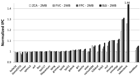
Based on our results, we conclude that BI, with its low decompression latency and high degree of compression, provides the best performance compared to all examined compression mechanisms.
3.9 Summary
In this chapter, we presented BI, a new and simple, yet efficient hardware cache compression technique that provides high effective cache capacity increase and system performance improvement compared to three state-of-the-art cache compression techniques. BI achieves these benefits by exploiting the low dynamic range of in-cache data and representing cache lines in the form of two base values (with one implicit base equal to zero) and an array of differences from these base values. We provide insights into why BI compression is effective via examples of existing in-cache data patterns from real programs. BI’s key advantage over previously proposed cache compression mechanisms is its ability to have low decompression latency (due to parallel decompression) while still having a high average compression ratio.
We describe the design and operation of a cache that can utilize BI compression with relatively modest hardware overhead. Our extensive evaluations across a variety of workloads and system configurations show that BI compression in an L2 cache can improve system performance for both single-core (8.1%) and multi-core workloads (9.5% / 11.2% for two/four cores), outperforming three state-of-the-art cache compression mechanisms. In many workloads, the performance benefit of using BI compression is close to the performance benefit of doubling the L2/L3 cache size. In summary, we conclude that BI is an efficient and low-latency data compression substrate for on-chip caches in both single- and multi-core systems.
Chapter 4 Compression-Aware Cache Management
4.1 Introduction
Originally published as “Exploiting Compressed Block Size as an Indicator of Future Reuse” in the 21st International Symposium on High Performance Computer Architecture, 2015 [181].Off-chip main memory latency and bandwidth are major performance bottlenecks in modern systems. Multiple levels of on-chip caches are used to hide the memory latency and reduce off-chip memory bandwidth demand. Efficient utilization of cache space and consequently better performance is dependent upon the ability of the cache replacement policy to identify and retain useful data. Replacement policies, ranging from traditional (e.g., [49, 26]) to state-of-the-art (e.g., [192, 96, 209, 115, 114, 190]), work using a combination of eviction (identifies the block to be removed from the cache), insertion (manages the initial block priority), and promotion (changes the block priority over time) mechanisms. In replacement policies proposed for conventional cache organizations, these mechanisms usually work by considering only the locality of the cache blocks.
A promising approach to improving effective cache capacity is to use cache compression (e.g., [256, 20, 10, 38, 73, 185, 203, 16]). In compressed caches, data compression algorithms, e.g., Frequent Pattern Compression (FPC) [11], Base-Delta-Immediate Compression (BDI) [185], and Frequent Value Compression [256], are used to achieve higher effective capacity (storing more blocks of data) and to decrease off-chip bandwidth consumption compared to traditional organizations without compression. This compression generates variable-size cache blocks, with larger blocks consuming more cache space than smaller blocks. However, most cache management policies in these compressed cache designs do not use block size in cache management decisions [256, 10, 38, 73, 185, 203, 16]. Only one recent work—ECM [20]—uses the block size information, but its effectiveness is limited by its coarse-grained (big vs. small) view of block size. The need to consider size along with temporal locality is well known in the context of web caches [199, 58, 4, 39, 21], but proposed solutions rely on a recency list of all objects in the web cache [4] or consider frequency of object accesses [39] and are usually prohibitively expensive to implement in hardware for use with on-chip caches.
In this chapter, we propose a Compression-Aware Management Policy (CAMP) that takes into account compressed cache block size along with temporal locality to improve the performance of compressed caches. Compared to prior work (ECM [20]), our policies first use a finer-grained accounting for compressed block size and an optimization-based approach for eviction decisions. Second and more importantly, we find that size is not only a measure of the cost of retaining a given block in the cache, as previous works considered [20], but it is sometimes also an indicator of block reuse. CAMP contains two key components, Minimal-Value Eviction (MVE) and Size-based Insertion Policy (SIP), which significantly improve the quality of replacement decisions in compressed caches (see Section 4.6 for a comprehensive analysis) at a modest hardware cost.
Minimal-Value Eviction (MVE). MVE is based on the observation that one should evict an uncompressed block with good locality to make/retain room for a set of smaller compressed blocks of the same total size, even if those blocks individually have less locality, as long as the set of blocks collectively provides more hits cumulatively. A special case of this is that when two blocks have similar locality characteristics, it is preferable to evict the larger cache block. MVE measures the value of each block as a combination of its locality properties and size. When an eviction is required (to make space for a new block), MVE picks the block with the least value as the victim.
Size-based Insertion Policy (SIP). SIP is based on our new observation that the compressed size of a cache block can sometimes be used as an indicator of its reuse characteristics. This is because elements belonging to the same data structure and having the same access characteristics are sometimes (but not always) compressed to the same size—e.g., in bzip2 [217], a compressed block of 34 bytes (with BDI compression [185]) likely belongs to one particular array with narrow values (e.g., small values stored in large data types) as we show in Section 4.2.3—and these structures more often than not have a specific pattern of access and/or reuse distance.
By dynamically inserting blocks of different sizes with either high priority—e.g., in the most-recently-used position for the LRU policy (ensuring blocks stay in cache longer)—or low priority—e.g., in the least-recently-used position for the LRU policy (ensuring blocks get evicted quickly unless reused shortly)—SIP learns the reuse characteristics associated with various compressed block sizes and, if such an association exists, uses this information to maximize the hit ratio.

As demonstrated later in this chapter, CAMP (a combination of MVE and SIP) works with both traditional compressed cache designs and compressed caches having decoupled tag and data stores (e.g., V-Way Cache [195] and Indirect Index Cache [72, 73]). It is general enough to be used with different compression mechanisms and requires only modest hardware changes. Compared to prior work, CAMP provides better performance, more efficient cache utilization, reduced off-chip bandwidth consumption, and an overall reduction in the memory subsystem energy requirements.
In summary, we make the following major contributions:
-
•
We make the observation that the compressed size of a cache block can be indicative of its reuse. We use this observation to develop a new cache insertion policy for compressed caches, the Size-based Insertion Policy (SIP), which uses the size of a compressed block as one of the metrics to predict its potential future reuse.
-
•
We introduce a new compressed cache replacement policy, Minimal-Value Eviction (MVE), which assigns a value to each cache block based on both its size and its reuse and replaces the set of blocks with the least value.
- •
-
•
We qualitatively and quantitatively compare CAMP (SIP + MVE) to the conventional LRU policy and three state-of-the-art cache management policies: two size-oblivious policies (RRIP [96] and a policy used in V-Way [195]) and the recent ECM [20]. We observe that CAMP (and its global variant G-CAMP) can considerably (i) improve performance (by 4.9%/9.0%/10.2% on average in single-/two-/four-core workload evaluations and up to 20.1%), (ii) decrease off-chip bandwidth consumption (by 8.7% in single-core), and (iii) decrease memory subsystem energy consumption (by 7.2% in single-core) on average for memory intensive workloads when compared with the best prior mechanism.
4.2 Motivating Observations
Cache compression [256, 20, 10, 38, 73, 185, 203, 16] is a powerful mechanism that increases effective cache capacity and decreases off-chip bandwidth consumption.111 Data compression can be also effective in increasing the size of the main memory [57, 179, 184] and reducing the off-chip memory bandwidth/energy consumption [184, 213]. In this section, we show that cache compression adds an additional dimension to cache management policy decisions – the compressed block size (or simply the size), which plays an important role in building more efficient management policies. We do this in three steps.
4.2.1 Size Matters
In compressed caches, one should design replacement policies that take into account compressed cache block size along with locality to identify victim blocks, because such policies can outperform existing policies that rely only on locality. In fact, Belady’s optimal algorithm [26] that relies only on locality (using perfect knowledge to evict the block that will be accessed furthest in the future) is sub-optimal in the context of compressed caches with variable-size cache blocks. Figure 4.1 demonstrates one possible example of such a scenario. In this figure, we assume that cache blocks are one of two sizes: (i) uncompressed 64-byte blocks (blocks X and Y) and (ii) compressed 32-byte blocks (blocks A, B, and C). We assume the cache capacity is 160 bytes. Initially (see ➊), the cache contains four blocks: three compressed (A, B, C) and one uncompressed (Y). Consider the sequence of memory requests X, A, Y, B, C, B, Y, and A (see ➋). In this case, after a request for X, Belady’s algorithm (based on locality) evicts blocks B and C (to create 64 bytes of free space) that will be accessed furthest into the future. Over the next four accesses, this results in two misses (B and C) and two hits (A and Y).
In contrast, a size-aware replacement policy can detect that it might be better to retain a set of smaller compressed cache blocks that receive more hits cumulatively than a single large (potentially uncompressed) cache block with better locality. For the access pattern discussed above, a size-aware replacement policy makes the decision to retain B and C and evict Y to make space for X (see ➌). As a result, the cache experiences three hits (A, B, and C) and only one miss (Y) and hence outperforms Belady’s optimal algorithm.222Later (see ➍), when there are three requests to blocks B, Y, and A (all three hits), the final cache state becomes the same as the initial one. Hence, this example can represent steady state within a loop. We conclude that using block size information in a compressed cache can lead to better replacement decisions.
4.2.2 Size Varies
Figure 4.2 shows the distribution of compressed cache block sizes333Section 4.5 describes the details of our evaluation methodology for this and other experiments. for a set of representative workloads given a 2MB cache employing the Base-Delta-Immediate (BDI) [185] cache compression algorithm (our results with the FPC [10] compression algorithm show similar trends). Even though the size of a compressed block is determined by the compression algorithm, under both designs, compressed cache block sizes can vary significantly, both (i) within a single application (i.e., intra-application) such as in astar, povray, and gcc and (ii) between applications (i.e., inter-application) such as between h264ref and wrf.
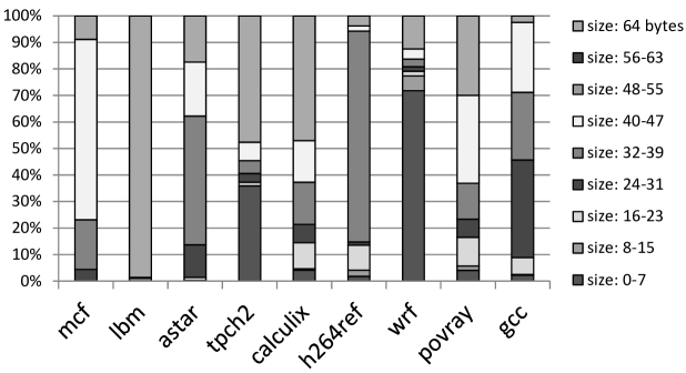
Size variation within an application suggests that size-aware replacement policies could be effective for individual single-core workloads. Intra-application variation exists because applications have data that belong to different common compressible patterns (e.g., zeros, repeated values, and narrow values [185]) and as a result end up with a mix of compressed cache block sizes. In a system with multiple cores and shared caches, inter-application variation suggests that even if an application has a single dominant compressed cache block size (e.g., lbm, h264ref and wrf), running these applications together on different cores will result in the shared cache experiencing a mix of compressed cache block sizes. Hence, size-aware management of compressed caches can be even more important for efficient cache utilization in multi-core systems (as we demonstrate quantitatively in Section 4.6.2).
4.2.3 Size Can Indicate Reuse
We observe that elements belonging to the same data structure (within an application) sometimes lead to cache blocks that compress to the same size. This observation provides a new opportunity: using the compressed size of a cache block as an indicator of data reuse of the block.
Intuition. We first briefly provide intuition on why there can be a relationship between compressed size and the reuse characteristics of the cache block. As past work has shown, an application’s key data structures are typically accessed in a regular fashion, with each data structure having an identifiable access pattern [5]. This regularity in accesses to a data structure can lead to a dominant reuse distance [51] range for the cache blocks belonging to the data structure.444Some prior works (e.g., [78, 112, 186, 234]) captured this regularity by learning the relationship between the instruction address and the reuse distance. The same data structure can also have a dominant compressed cache block size, i.e., a majority of the cache blocks containing the data structure can be compressed to one or a few particular sizes (e.g., due to narrow or sparse values stored in the elements of an array). For such a data structure, the compressed cache block size can therefore be a good indicator of the reuse behavior of the cache blocks. In fact, different data structures can have different dominant compressed block sizes and different dominant reuse distances; in such cases, the compressed block size serves as a type of signature indicating the reuse pattern of a data structure’s cache blocks.
Example to Support the Intuition. To illustrate the connection between compressed block size and reuse behavior of data structures intuitively, Figure 4.3 presents an example loosely based on some of the data structures we observed in soplex. There are three data structures in this example: (i) array of integer indexes that are smaller than value (well-compressible with BDI [185] to 20-byte cache blocks), (ii) small array of floating point coefficients (incompressible, 64-byte cache blocks), and (iii) sparse matrix with the main data (very compressible zero values, many 1-byte cache blocks). These data structures not only have different compressed block sizes, but also different reuse distances. Accesses to cache blocks for array occur only once every iteration of the outer loop (long reuse distance). Accesses to cache blocks for array occur roughly every iteration of the inner loop (short reuse distance). Finally, the reuse distance of array is usually long, although it is dependent on what indexes are currently stored in array . Hence, this example shows that compressed block size can indicate the reuse distance of a cache block: 20-byte blocks (from ) usually have long reuse distance, 64-byte blocks (from ) usually have short reuse distance, and 1-byte blocks (from ) usually have long reuse distance. If a cache learns this relationship, it can prioritize 64-byte blocks over 20-byte and 1-byte blocks in its management policy. As we show in Section 4.3.3, our SIP policy learns exactly this kind of relationship, leading to significant performance improvements for several applications (including soplex), as shown in Section 4.6.1.555Note that our overall proposal also accounts for the size of the block, e.g., that a 64-byte block takes up more space in the cache than a 20-byte or 1-byte block, via the use of MVE policy (Section 4.3.2).
Quantitative Evidence. To verify the relationship between block size and reuse, we have analyzed 23 memory-intensive applications’ memory access traces (applications described in Section 4.5). For every cache block within an application, we computed the average distance (measured in memory requests) between the time this block was inserted into the compressed cache and the time when it was reused next. We then accumulate this reuse distance information for all different block sizes, where the size of a block is determined with the BDI [185] compression algorithm.
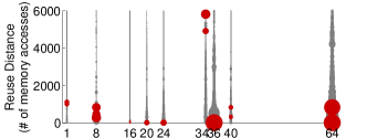
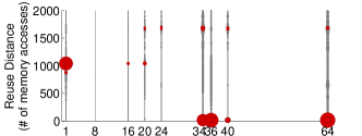
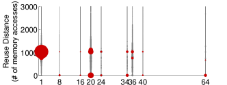
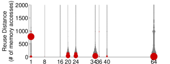
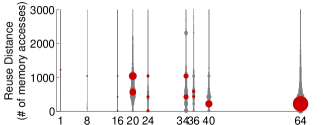
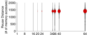
Figures 4.4(a)–4.4(f) show the results of this analysis for nine representative applications from our workload pool (our methodology is described in Section 4.5). In five of these applications (bzip2, sphinx3, soplex, tpch6, gcc), compressed block size is an indicator of reuse distance (in other words, it can be used to distinguish blocks with different reuse distances). In one of the applications (mcf), it is not. Each graph is a scatter plot that shows the reuse distance distribution experienced by various compressed cache block sizes in these applications. There are nine possible compressed block sizes (based on the description from the BDI work [185]). The size of each circle is proportional to the relative frequency of blocks of a particular size that exhibit a specified reuse distance. The dark red circles indicate the most frequent reuse distances (up to three) for every size.
We make three major observations from these figures. First, there are many applications where block size is an indicator of reuse distance (Figure 4.4(a)–4.4(f)). For instance, in bzip2 (Figure 4.4(a)), a large number of cache blocks are 8, 36, or 64 (uncompressed) bytes and have a short reuse distance of less than 1000. In contrast, a significant number of blocks are 34 bytes and have a large reuse distance of greater than 5000. This indicates that the 34-byte blocks can be deprioritized by the cache when running bzip2 to improve performance. Similarly, in sphinx3, tpch6, and soplex (Figures 4.4(b)–4.4(d)), a significant number of blocks are compressed to 1-byte with a long reuse distance of around 1000, whereas most of the blocks of other sizes have very short reuse distances of less than 100. In general, we observe that data from 15 out of 23 of our evaluated applications show that block size is indicative of reuse [180]. This suggests that a compressed block size can be used as an indicator of future block reuse which in turn can be used to prioritize blocks of certain sizes (Section 4.3.3), improving application performance (e.g., see the effect on soplex in Section 4.6.1).
Second, there are some applications where block size does not have a relationship with reuse distance of the block (e.g., mcf). For example, in mcf (Figure 4.4(f)), almost all blocks, regardless of their size, have reuse distances around 1500. This means that block size is less effective as an indicator of reuse for such applications (and the mechanism we describe in Section 4.3.3 effectively avoids using block size in cache management decisions for such applications).
Third, for applications where block size is indicative of reuse, there is usually not a coarse-grained way to distinguish between block sizes that are indicative of different reuse distances. In other words, simply dividing the blocks into big or small blocks, as done in ECM [20], is not enough to identify the different reuse behavior of blocks of different sizes. The distinction between block sizes should be done at a finer granularity. This is evident for bzip2 (Figure 4.4(a)): while 8, 36, and 64-byte blocks have short reuse distances, a significant fraction of the 34-byte blocks have very long reuse distances (between 5000 and 6000). Hence, there is no single block size threshold that would successfully distinguish blocks with high reuse from those with low reuse. Data from other applications (e.g., soplex, gcc) similarly support this.
We briefly discuss why compressed size is sometimes not indicative of reuse behavior. First, data stored in the data structure might be different, so multiple compressed sizes are possible with the same reuse pattern (e.g., for mcf). In this case, blocks of different sizes are equally important for the cache. Second, blocks with the same size(s) can have multiple different reuse patterns/distances (e.g., for milc and gromacs). In this case, size might not provide useful information to improve cache utilization, because blocks of the same size can be of very different importance.
4.3 CAMP: Design and Implementation
Our proposed Compression-Aware Management Policy (CAMP) consists of two components: Minimal-Value Eviction (MVE) and Size-based Insertion Policy (SIP). These mechanisms assume a compressed cache structure where the compressed block size is available to the hardware making the insertion and replacement decisions. Without the loss of generality, we assume that the tag-store contains double the number of tags and is decoupled from the data-store to allow higher effective capacity (as proposed in several prior works [10, 185, 38]). We also propose Global CAMP (or G-CAMP), an adaptation of CAMP for a cache with a global replacement policy.
In this section, we first provide the background information needed to understand some of our mechanisms (Section 4.3.1). Then, we describe the design and implementation of each mechanism in depth (Sections 4.3.2-4.3.4). We detail the implementation of our G-CAMP mechanism assuming the structure proposed for the V-Way cache [195]. None of the mechanisms require extensive hardware changes on top of the baseline compressed cache designs (both local and global, see Section 4.3.5 for an overhead analysis).
4.3.1 Background
Multiple size-oblivious cache management mechanisms (e.g., [192, 96, 209, 115, 114]) were proposed to improve the performance of conventional on-chip caches (without compression). Among them, we select RRIP [96] as both a comparison point in our evaluations and as a predictor of future re-reference in some of our algorithms (see Section 4.3.2). This selection is motivated both by the simplicity of the algorithm and its state-of-the-art performance (as shown in [96]).
RRIP. Re-Reference Interval Prediction (RRIP) [96] uses an -bit saturating counter per cache block as a Re-Reference Prediction Value () to predict the block’s re-reference distance. The key idea behind RRIP is to prioritize the blocks with lower predicted re-reference distance, as these blocks have higher expectation of near-future reuse. Blocks are inserted with a long re-reference interval prediction (). On a cache miss, the victim block is a block with a predicted distant re-reference interval (). If there is no such block, the of all blocks is incremented by one and the process repeats until a victim is found. On a cache hit, the of a block is set to zero (near-immediate re-reference interval). Dynamic RRIP (DRRIP) uses set dueling [192, 190] to select between the aforementioned policy (referred to as SRRIP) and one that inserts blocks with a short re-reference interval prediction with high probability and inserts blocks with a long re-reference interval prediction with low probability.
V-Way. The Variable-Way, or V-Way [195], cache is a set-associative cache with a decoupled tag- and data-store. The goal of V-Way is two-fold: providing flexible (variable) associativity together with a global replacement across the entire data store. A defining characteristic is that there are more tag-entries than data-entries. Forward and backward pointers are maintained in the tag- and data-store to link the entries. This design enables associativity to effectively vary on a per-set basis by increasing the number of tag-store entries relative to data-store entries. Another benefit is the implementation of a global replacement policy, which is able to choose data-victims from anywhere in the data-store. This is in contrast to a traditional local replacement policy, e.g., [49, 96], which considers data-store entries only within a single set as possible victims. The particular global replacement policy described in [195] (called Reuse Replacement) consists of a Reuse Counter Table (RCT) with a counter for each data-store entry. Victim selection is done by starting at a pointer (PTR) to an entry in the RCT and searching for the first counter equal to zero, decrementing each counter while searching, and wrapping around if necessary. A block is inserted with an RCT counter equal to zero. On a hit, the RCT counter for the block is incremented. We use the V-Way design as a foundation for all of our global mechanisms (described in Section 4.3.4).
4.3.2 Minimal-Value Eviction (MVE)
The key observation in our MVE policy is that evicting one or more important blocks of larger compressed size may be more beneficial than evicting several more compressible, less important blocks (see Section 4.2). The idea behind MVE is that each block has a value to the cache. This value is a function of two key parameters: (i) the likelihood of future re-reference and (ii) the compressed block size. For a given prediction of re-reference, compressed block size tuple, MVE associates a value with the block. Intuitively, a block with higher likelihood of re-reference is more valuable than a block with lower likelihood of re-reference and is assigned a higher value. Similarly, a more compressible block is more valuable than a less compressible block because it takes up fewer segments in the data-store, potentially allowing for the caching of additional useful blocks. The block with the least value in the associativity set is chosen as the next victim for replacement—sometimes multiple blocks need to be evicted to make room for the newly inserted block.
In our implementation of MVE, the value of a cache block is computed as , where is the compressed block size of block and is a predictor of re-reference, such that a larger value of denotes block is more important and is predicted to be re-referenced sooner in the future. This function matches our intuition and is monotonically increasing with respect to the prediction of re-reference and monotonically decreasing with respect to the size. We have considered other functions with these properties (i.e., a weighted linear sum), but found the difference in performance to be negligible.
Our mechanism estimates using RRIP666Specifically, the version of RRIP that our mechanism uses is SRRIP. We experimented with DRRIP, but found it offered little performance improvement for our mechanisms compared to the additional complexity. All of our evaluations assume an RRPV width . [96] as the predictor of future re-reference due to its simple hardware implementation and state-of-the-art stand-alone performance.777Other alternatives considered (e.g., [209]) provide only a binary value. As described in Section 4.3.1, RRIP maintains a re-reference prediction value (RRPV) for each cache block which predicts the re-reference distance. Since a larger RRPV denotes a longer predicted re-reference interval, we compute as . Therefore, a block with a predicted short re-reference interval has more value than a comparable block with a predicted long re-reference interval. cannot be zero, because would lose dependence on and become size-oblivious.
Depending on the state of the cache, there are two primary conditions in which a victim block must be selected: (i) the data-store has space for the block to be inserted, but all tags are valid in the tag-directory, or (ii) the data-store does not have space for the block to be inserted (an invalid tag may or may not exist in the tag-directory). In the first case where the data-store is not at capacity, MVE relies solely on the predictor of re-reference or conventional replacement policy, such as RRIP. For the second case, the valid blocks within the set are compared based on and the set of blocks with the least value is evicted to accommodate the block requiring insertion.
MVE likely remains off the critical path, but to simplify the microarchitecture, we eliminate division in the calculation of by bucketing block sizes such that is always a power of two, allowing a simple right-shift operation instead of floating point division. For the purposes of calculating , for blocks of size 0B – 7B, for blocks of size 8B – 15B, for blocks of size 16B – 31B, and so on. The most complex step, comparing blocks by value, can be achieved with a fixed multi-cycle parallel comparison.
4.3.3 Size-based Insertion Policy (SIP)
The key observation behind SIP is that sometimes there is a relation between cache block reuse distance and compressed block size (as shown in Section 4.2.3). SIP exploits this observation and inserts blocks of certain sizes with higher priority if doing so reduces the cache miss rate. Altering the priority of blocks of certain sizes with short or long reuse distances helps to ensure that more important blocks stay in the cache.
At run-time, SIP dynamically detects the set of sizes that, when inserted with higher priority, reduce the number of misses relative to a size-oblivious insertion policy. SIP uses a simple mechanism based on dynamic set sampling [192] to make the prioritization decision for various compressed sizes. It selects the best-performing policy among competing policies during a periodic training phase and applies that policy during steady state. The observation in dynamic set sampling is that sampling makes it possible to choose the better policy with only a relatively small number of sets selected from the Main Tag Directory (MTD) to have a corresponding set in an Auxiliary Tag Directory (ATD) participating in a tournament. Only the MTD is coupled with the data-store; the ATD is only for deciding which block size(s) should be inserted with high priority. Therefore, there are no performance degradations due to our sampling during training.
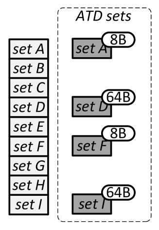
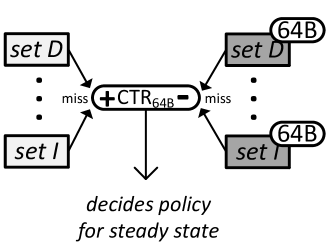
Let be the minimum number of sets that need to be sampled so that dynamic set sampling can determine the best policy with high probability and be the number of compressible block sizes possible with the compression scheme (e.g., 8B, 16B, 20B, …, 64B). In SIP, the ATD contains sets, for each of the sizes. As shown in Figure 4.5, each set in the ATD is assigned one of the sizes. The insertion policy in these sets of the ATD differs from the insertion policy in the MTD in that the assigned size is prioritized. For the example in Figure 4.5, there are only two possible block sizes. Sets A and F in the ATD prioritize insertions of 8-byte blocks (e.g., by increasing ). Sets D and I prioritize the insertion of 64-byte blocks. Sets B, C, E, G, and H are not sampled in the ATD.
When a set in the MTD that has a corresponding set in the ATD receives a miss, a counter is incremented, where i is a size corresponding to the prioritized size in the corresponding ATD set. When an ATD set receives a miss, it decrements for the size associated with the policy this set is helping decide. Figure 4.5 shows the decision of the output of .
For each of the possible compressed block sizes, a decision is made independently based on the result of the counter. If is negative, prioritizing blocks of size i is negatively affecting miss rate (e.g., the insertion policy in the MTD resulted in fewer misses than the insertion policy in the ATD). Therefore, SIP does not prioritize blocks of size i. Likewise, if is positive, prioritizing insertion of blocks of size i is reducing the miss rate and SIP inserts size i blocks with high priority for best performance. For different sizes, there are possible insertion schemes and any may be chosen by SIP.
For simplicity and to reduce power consumption, the dynamic set sampling occurs during a periodic training phase888In our evaluations, we perform training for 10% of the time. For example, for 100 million cycles every 1 billion cycles. at which time the insertion policy of the MTD is unaffected by SIP. At the conclusion of the training phase, a steady state is entered and the MTD adopts the chosen policies and prioritizes the insertion of blocks of sizes for which was positive during training.
SIP is general enough to be applicable to many replacement policies (e.g., LRU, RRIP, etc). In some cases (e.g., LRU), it is more effective to try inserting blocks with lower priority (e.g., LRU position) instead of higher priority as proposed above. We evaluate SIP with RRIP where blocks by default are inserted with a predicted long re-reference interval (). Therefore, in the ATD sets, the appropriate sizes are prioritized and inserted with a predicted short re-reference interval (). For a 2MB cache with 2048 sets, we create an ATD with 32 sets for each of 8 possible block sizes. For simplicity, in our implementation we limit the number of sizes to eight by bucketing the sizes into eight size bins (i.e., bin one consists of sizes 0 – 8B, bin two consists of sizes 9 – 16B,…, and bin eight consists of sizes 57 – 64B).
4.3.4 CAMP for the V-Way Cache
In addition to being an effective mechanism for the traditional compressed cache with a local replacement policy, the key ideas behind CAMP are even more effective when applied to a cache with a decoupled tag- and data-store and a global replacement policy, where the pool of potential candidates for replacement is much larger. In this work, we apply these ideas to the V-Way cache [195] (described in Section 4.3.1) with its decoupled tag- and data-store that increase the effectiveness of replacement algorithms. To demonstrate this effectiveness, we propose Global SIP (or G-SIP) and Global MVE (or G-MVE). Together, we combine these into Global CAMP (or G-CAMP).
V-Way cache + compression. The V-Way cache [195] design can be enhanced with compression in four main steps (as shown in Figure 4.6). First, the tag entries need to be extended with the encoding bits to represent a particular compression scheme used for a cache block (e.g., 4 bits for BDI [185], see ➊). The number of tags is already doubled in the V-Way cache. Second, the data store needs to be split into multiple segments to get the benefit of compression (e.g., 8-byte segments, see ➋). As in [185], every cache block after compression consists of multiple adjacent segments. Third, the reverse pointers () that are used to perform the replacement need to track not only the validity (v bit) but also the size of each block after compression (measured in the number of 8-byte segments, ➌). This simplifies the replacement policies, because there is no need to access the tags to find block sizes. Fourth, we double the number of reverse pointers per set, so that we can exploit the capacity benefits from compression (➍).
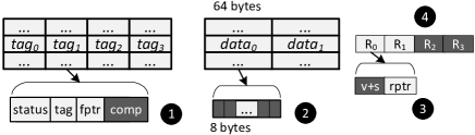
For a 2MB V-Way-based L2 cache with 64-byte cache blocks, the sizes of the fptr and rptr pointers are 15 () and 16 () bits respectively. After compression is applied and assuming 8-byte segments, fptr would increase by 3 bits to a total size of 18 bits.999Fptr and rptr pointers can be reduced in size (by 3 bits) by using regioning (as described later in Section 4.6). A single validity bit that was used in V-Way cache is now enhanced to 3 bits to represent 7 different sizes of the cache blocks after compression with BDI as well as the validity itself.
G-MVE. As in MVE, G-MVE uses a value function to calculate the value of blocks. The changes required are in (i) computing and (ii) selecting a pool of blocks from the large pool of replacement options to consider for one global replacement decision. To compute , we propose using the reuse counters from the Reuse Replacement policy [195] as a predictor of future re-reference. As in the Reuse Replacement policy [195] (see Section 4.3.1), each data-store entry has a counter. On insertion, a block’s counter is set to zero. On a hit, the block’s counter is incremented by one indicating its reuse.
For the second change, we implement global replacement by maintaining a pointer (PTR) to a reuse counter entry. Starting at the entry PTR points to, the reuse counters of 64 valid data entries are scanned, decrementing each non-zero counter by one (as in the Reuse Replacement policy). The 64 blocks are assigned a value, , and the least-valued block(s) are evicted to accommodate the incoming block. 64 blocks are chosen because it guarantees both an upper bound on latency and that evicting all 64 blocks (i.e., all highly compressed blocks) in the worst case will vacate enough data-store space for the incoming block.
A few applications (i.e., xalancbmk [217]) have a majority of blocks of very similar sizes that primarily belong to two size bins of adjacent sizes. When considering 64 such blocks, certain blocks in the smaller size bin can essentially be “stuck” in the cache (i.e., there is only a very small probability these blocks will be chosen as victim, because a block with the same prediction of re-reference that belongs in the larger size bin is present and will be chosen). This results from the microarchitectural simplifications and approximate nature of the value function and can cause performance degradations in a few cases. We address this shortcoming later in this section.
G-SIP. Dynamic set sampling (used by SIP) motivates that only a select number of sets are required to be sampled to estimate the performance of competing policies [192]. However, this assumption does not hold in a cache with global replacement, because evictions are not limited to the set in which a cache miss occurs and this interferes with sampling. For the V-Way cache, we propose instead a mechanism inspired by set dueling [190] to select the optimal insertion policy.
To apply set dueling to G-SIP, we need to divide the data-store into (where is small; in our evaluations ) equal regions. Instead of considering all blocks within the data-store, the replacement policy considers only the blocks within a particular region. This still allows considerably more replacement options than a traditional cache structure. We observe that this division also simplifies the V-Way cache design with negligible impact on performance.101010G-MVE supports regions by simply maintaining one PTR per region.
During a training phase, each region is assigned a compressed block size to prioritize on insertion. Figure 4.7 shows this assignment for a simple cache with three regions and two block sizes, 8-byte and 64-byte. The third region is designated as a baseline (or control) region in which no blocks are inserted with higher priority. When a miss occurs within a region, the counter is incremented for that region. For example, in Figure 4.7, a miss to set A, B, or C increments . Likewise, a miss to set G, H, or I increments and so on. At the end of the training phase, the region counters are compared (see Figure 4.7). If , blocks of size are inserted with higher priority in steady state in all regions. Therefore, G-SIP detects at runtime the sizes that reduce the miss rate when inserted with higher priority than other blocks.
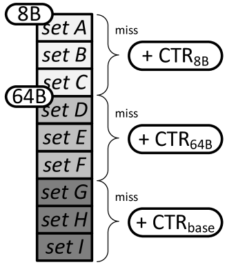
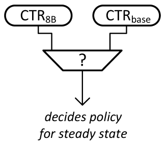
In our implementation, we have divided the data-store into eight regions.111111We conducted an experiment varying the number of regions (and therefore the number of distinct size bins considered) from 4 to 64 and found having 8 regions performed best. This number can be adjusted based on cache size. Because one region is designated as the baseline region, we bin the possible block sizes into seven bins and assign one range of sizes to each region. During the training phase, sizes within this range are inserted with higher priority. The training duration and frequency are as in SIP. Because training is short and infrequent, possible performance losses due to set dueling are limited.
G-CAMP. G-MVE and G-SIP complement each other and can be easily integrated into one comprehensive replacement policy referred to as G-CAMP. We make one improvement over the simple combination of these two orthogonal policies to further improve performance in the few cases where G-MVE degrades performance. During the training phase of G-SIP, we designate a region in which we insert blocks with simple Reuse Replacement instead of G-MVE. At the end of the training phase, the for this region is compared with the control region and if fewer misses were incurred, G-MVE is disabled in all regions at the steady state. In G-MVE-friendly applications, it remains enabled.
4.3.5 Overhead and Complexity Analysis
Table 4.1 shows the storage cost of six cache designs: baseline uncompressed cache, BDI compressed cache with LRU, V-Way with and without compression, as well as CAMP and G-CAMP. On top of our reference cache with BDI and LRU (2384kB), MVE does not add any additional metadata and the dynamic set sampling in SIP increases the cache size in bits by only 1.5% (total CAMP size: 2420kB). Adding BDI compression to V-Way cache with 2x tags and 8 regions increases cache size from 2458kB to 2556kB. G-MVE/G-SIP/G-CAMP do not add further metadata (with the exception of eight 16-bit counters for set-dueling in G-SIP/G-CAMP). In addition, none of the proposed mechanisms are on the critical path of the execution and the logic is reasonably modest to implement (e.g., comparisons of CTRs). We conclude that the complexity and storage overhead of CAMP are modest.
| Base | BDI | CAMP | V-Way | V-Way+C | G-CAMP | |
| tag-entry(bits) | 21 | 35([185]) | 35 | 36 121212+15 forward ptr; b +16 reverse ptr; c+1/8 set sampling in SIP; dCTR’s in SIP; e +4 for comp. encoding; f +32 (2 reverse ptrs per data entry, 13 bits each, and 2 extended validity bits, 3 bits each) | 40 e | 40 |
| data-entry(bits) | 512 | 512 | 512 | 528 b | 544 f | 544 |
| # tag entries | 32768 | 65536 | 73728 c | 65536 | 65536 | 65536 |
| # data entries | 32768 | 32768 | 32768 | 32768 | 32768 | 32768 |
| tag-store (kB) | 86 | 287 | 323 | 295 | 328 | 328 |
| data-store (kB) | 2097 | 2097 | 2097 | 2163 | 2228 | 2228 |
| other | 0 | 0 | 8*16 d | 0 | 0 | 8*16 |
| total (kB) | 2183 | 2384 | 2420 | 2458 | 2556 | 2556 |
4.4 Qualitative Comparison with Prior Work
4.4.1 Size-Aware Management in On-Chip Caches
Baek et al. propose Effective Capacity Maximizer (ECM) [20]. This mechanism employs size-aware insertion and replacement policies for an on-chip compressed cache. Unlike size-oblivious DRRIP [96] on which it is built, ECM inserts big blocks with lower priority than small blocks. The threshold for what is considered a “big” block is determined dynamically at runtime using an equation derived from heuristics and based on the current effective capacity and physical memory usage. During replacement, the biggest block in the eviction pool is selected as the victim.
ECM is the first size-aware policy employed for compressed on-chip caches. We find that this approach has several shortcomings and underperforms relative to our proposed mechanisms (as we show in Section 4.6). First, the threshold scheme employed by ECM is coarse-grained and, especially in multi-core workloads where a greater diversity of block sizes exists across workloads, considering more sizes (as CAMP does) yields better performance. Second, ECM’s mechanism does not consider the relation between block reuse and size, whereas CAMP exploits the new observation that block size and reuse can sometimes be related. Third, due to ECM’s complex threshold definition, it is unclear how to generalize ECM to a cache with global replacement, where size-aware replacement policies demonstrate highest benefit (as shown in Section 4.6). In contrast, CAMP is easily adapted to work with such caches.
Recently, Sardashti and Wood propose the decoupled compressed cache (DCC) design [203] that exploits both locality and decoupled sectored cache design to avoid recompaction (and partially fragmentation) overhead in the previous compressed cache designs. The DCC design is largely orthogonal to the compression mechanisms proposed in this work and can be used in cojunction with them.
4.4.2 Size-Aware Management in Web Caches
Prior works in web caches have proposed many management strategies that consider object size, e.g., variable document size. ElAarag and Romano [199, 58] provide one of the most comprehensive surveys. While these proposed techniques serve the same high-level purpose as a management policy for an on-chip cache (e.g., making an informed decision on the optimal victim), they do so in a much different environment. Many proposed mechanisms rely on a recency list of all objects in the cache (e.g., [4]) or consider frequency of object access (e.g., [39]), which are prohibitively expensive techniques for an on-chip cache. In addition, these techniques do not consider a higher density of information that comes with the smaller blocks after compression. This higher density can lead to a higher importance of the smaller blocks for the cache, which was mostly ignored in these prior mechanisms.
Some prior works (e.g., [21, 32]) proposed function-based replacement policies that calculate the value of an object much like our proposed MVE policy. In particular, Bahn et al. [21] proposed a mechanism where the value of a block is computed as the division of re-reference probability and the relative cost of fetching by size. Similar to other function-based techniques, however, these inputs cannot efficiently be computed or stored in hardware. Our proposed technique does not suffer from this problem and requires only simple metrics already built into on-chip caches.
4.5 Methodology
We use an in-house, event-driven 32-bit x86 simulator [156] whose front-end is based on Simics [154]. All configurations have a two-level cache hierarchy, with private L1 caches and a shared, inclusive L2 cache. Table 4.2 provides major simulation parameters. All caches uniformly use a 64B cache block size. All cache latencies were determined using CACTI [229] (assuming a 4GHz frequency). We also checked that these latencies match the existing last-level cache implementations from Intel and AMD, when properly scaled to the corresponding frequency.131313Intel Xeon X5570 (Nehalem) 2.993GHz, 8MB L3 - 35 cycles [160]; AMD Opteron 2.8GHz, 1MB L2 - 13 cycles [37]. For single-core and multi-core evaluations, we use benchmarks from the SPEC CPU2006 suite [217], two TPC-H queries [232], and an Apache web server. All results are collected by running a representative portion (based on PinPoints [173]) of the benchmarks for 1 billion instructions. We build our energy model based on McPAT [143], CACTI [229], and on RTL of BDI [185] synthesized with Synopsys Design Compiler with a 65nm library (to evaluate the energy of compression/decompression with BDI).
4.5.1 Evaluation Metrics
We measure performance of our benchmarks using IPC (instruction per cycle), effective compression ratio (effective increase in L2 cache size without meta-data overhead, e.g., 1.5 for 2MB cache means effective size of 3MB), and MPKI (misses per kilo instruction). For multi-programmed workloads we use weighted speedup [216, 61] as the performance metric.
4.5.2 Energy
We measure the memory subsystem energy, which includes the static and dynamic energy consumed by L1 and L2 caches, memory transfers, and DRAM, as well as the energy of BDI’s compressor/decompressor units. Energy results are normalized to the energy of the baseline system with a 2MB compressed cache and an LRU replacement policy. BDI was fully implemented in Verilog and synthesized to create some of the energy results used in building our power model. The area overhead of the compression and decompression logic is (combined). Decompression power is 7.4 mW, and compression power is 20.59 mW on average.
Our results show that there are benchmarks that are almost insensitive (IPC improvement is less than 5% with 32x increase in cache size) to the size of the L2 cache: dealII, povray, calculix, gamess, namd. This typically means that their working sets mostly fit into the L1D cache, leaving almost no potential for any L2/memory optimization. Therefore, we do not present data in detail for these applications, although we verified that our mechanism does not affect their performance.
| Processor | 1–4 cores, 4GHz, x86 in-order |
|---|---|
| L1-D cache | 32KB, 64B cache-line, 2-way, 1 cycle, uncompressed |
| L2 caches | 1–16 MB, 64B cache-line, 16-way, 15–48 cycles |
| Memory | 300-cycle latency, 32 MSHRs |
4.5.3 Parameters of Evaluated Schemes
For FPC (BDI), we used a decompression latency of 5 cycles [11] (1 cycle [185]), respectively. We use a segment size of 1 byte for both designs to get the highest compression ratio as described in [11, 185], and an 8-byte segment size for V-Way-based designs. As in prior works [10, 185], we assume double the number of tags compared to the conventional uncompressed cache (and hence the compression ratio cannot be larger than 2.0).
4.6 Results and Analysis
4.6.1 Single-core Results
Effect on Performance
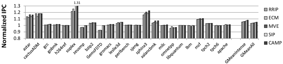
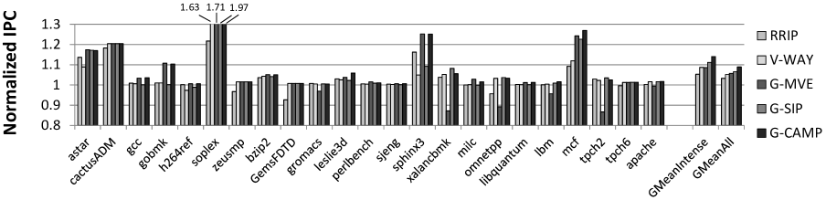
Figures 4.8 and 4.9 show the performance improvement of our proposed cache management policies over the baseline design with a 2MB compressed141414Unless otherwise stated, we use 2MB BDI [185] compressed cache design. L2 cache and an LRU replacement policy. Figure 4.8 compares the performance of CAMP’s local version (and its components: MVE and SIP) over (i) the conventional LRU policy [49], (ii) the state-of-the-art size-oblivious RRIP policy [96], and (iii) the recently proposed ECM policy [20]. Figure 4.9 provides the same comparison for G-CAMP (with its components: G-MVE and G-SIP) over (i) LRU, (ii) RRIP, and (iii) V-Way design [195]. Both figures are normalized to the performance of a BDI-cache with LRU replacement. Table 4.3 summarizes our performance results. Several observations are in order.
| Mechanism | LRU | RRIP | ECM |
|---|---|---|---|
| MVE | 6.3%/-10.7% | 0.9%/-2.7% | 0.4%/-3.0% |
| SIP | 7.1%/-10.9% | 1.8%/-3.1% | 1.3%/-3.3% |
| CAMP | 8.1%/-13.3% | 2.7%/-5.6% | 2.1%/-5.9% |
| Mechanism | LRU | RRIP | ECM | V-Way |
|---|---|---|---|---|
| G-MVE | 8.7%/-15.3% | 3.2%/-7.8% | 2.7%/-8.0% | 0.1%/-0.9% |
| G-SIP | 11.2%/-17.5% | 5.6%/-10.2% | 5.0%/-10.4% | 2.3%/-3.3% |
| G-CAMP | 14.0%/-21.9% | 8.3%/-15.1% | 7.7%/-15.3% | 4.9%/-8.7% |
First, our G-CAMP and CAMP policies outperform all prior designs: LRU (by 14.0% and 8.1%), RRIP (by 8.3% and 2.7%), and ECM (by 7.7% and 2.1%) on average across fourteen memory-intensive applications (GMeanIntense, with MPKI 5). These performance improvements come from both components in our design, which significantly decrease applications’ miss rates (shown in Table 4.3). For example, MVE and G-MVE are the primary sources of improvements in astar, sphinx3 and mcf, while SIP is effective in soplex and GemsFDTD. Note that if we examine all applications, then G-CAMP outperforms LRU, RRIP and ECM by 8.9%, 5.4% and 5.1% (on average).
Second, our analysis reveals that the primary reasons why CAMP/G-CAMP outperforms ECM are: (i) ECM’s coarse-grain view of the size (only large vs. small blocks are differentiated), (ii) ECM’s difficulty in identifying the right threshold for an application. For example, in soplex, ECM defines every block that is smaller than or equal to 16 bytes as a small block and prioritizes it (based on ECM’s threshold formula). This partially helps to improve performance for some important blocks of size 1 and 16, but our SIP mechanism additionally identifies that it is even more important to prioritize blocks of size 20 (a significant fraction of such blocks have short reuse distance as we show in Section 4.2.3). This in turn leads to much better performance in soplex by using CAMP (and G-CAMP).
Third, in many applications, G-MVE significantly improves performance (e.g., soplex and sphinx3), but there are some noticeable exceptions (e.g., xalancbmk). Section 4.6 describes the main reason for this problem. Our final mechanism (G-CAMP), where we use set dueling [190] to dynamically detect such situations and disable G-MVE (for these cases only) avoids this problem. As a result, our G-CAMP policy gets the best of G-MVE when it is effective and avoids degradations otherwise.
Fourth, global replacement policies (e.g., G-CAMP) are more effective in exploiting the opportunities provided by the compressed block size. G-CAMP not only outperforms local replacement policies (e.g., RRIP), but also global designs like V-Way (by 3.6% on average across all applications and by 4.9% across memory intensive applications).
We summarize the performance gains and the decrease in the cache miss rate (MPKI) for all our policies in Table 4.3. Based on our results, we conclude that our proposed cache management policies (G-CAMP and CAMP) are not only effective in delivering performance on top of the existing cache designs with LRU replacement policy, but also provide significant improvement over state-of-the-art mechanisms.
Sensitivity to the Cache Size
The performance benefits of our policies are significant across a variety of different systems with different cache sizes.
Figure 4.10 shows the performance of designs where (i) L2 cache size varies from 1MB to 16MB, and (ii) the replacement policies also vary: LRU, RRIP, ECM, V-Way, CAMP, and G-CAMP.151515All results are normalized to the performance of the 1MB compressed L2 cache with LRU replacement policy. Cache access latency is modeled and adjusted appropriately for increasing cache size, using CACTI. Two observations are in order.
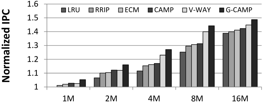
First, G-CAMP outperforms all prior approaches for all corresponding cache sizes. The performance improvement varies from 5.3% for a 1MB L2 cache to as much as 15.2% for an 8MB L2 cache. CAMP also outperforms all local replacement designs (LRU and RRIP).
Second, the effect of having size-aware cache management policies like G-CAMP, in many cases, leads to performance that is better than that of a twice-as-large cache with the conventional LRU policy (e.g, 4MB G-CAMP outperforms 8MB LRU). In some cases (e.g., 8MB), G-CAMP performance is better than that of a twice-as-large cache with any other replacement policy. We conclude that our management policies are efficient in achieving the performance of higher-capacity last-level cache without making the cache physically larger.
Effect on Energy
By decreasing the number of transfers between LLC and DRAM, our management policies also improve the energy consumption of the whole main memory hierarchy. Figure 7.3 shows this effect on the memory subsystem energy for two of our mechanisms (CAMP and G-CAMP) and three state-of-the-art mechanisms: (i) RRIP, (ii) ECM, and (iii) V-Way. Two observations are in order.
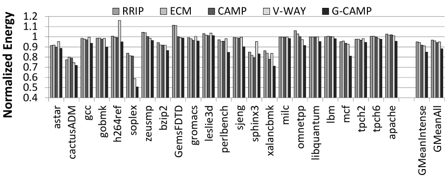
First, as expected, G-CAMP is the most effective in decreasing energy consumption due to the highest decrease in MPKI (described in Table 4.3). The total reduction in energy consumption is 15.1% on average for memory-intensive workloads (11.8% for all applications) relative to the baseline system and 7.2% relative to the best prior mechanism. We conclude that our cache management policies are more effective in decreasing the energy consumption of the memory subsystem than previously-proposed mechanisms.
Second, applications that benefit the most are usually the same applications that also have the highest performance improvement and the highest decrease in off-chip traffic, e.g., soplex and mcf. At the same time, there are a few exceptions, like perlbench, that demonstrate significant reduction in energy consumed by the memory subsystem, but do not show significant performance improvement (as shown in Figures 4.8 and 4.9). For these applications, the main memory subsystem is usually not a performance bottleneck due to the relatively small working set sizes that fit into the 2MB L2 cache and hence the relative improvements in the main memory subsystem might not have noticeable effects on the overall system performance.
Effect on Cache Capacity
We expect that size-aware cache management policies increase the effective cache capacity by increasing the effective compression ratio. Figure 4.12 aims to verify this expectation by showing the average compression ratios for applications in our workload pool (both the overall average and the average for memory-intensive applications). We make two major observations.
First, as expected, our size-aware mechanisms (CAMP/G-CAMP) significantly improve effective compression ratio over corresponding size-oblivious mechanisms (RRIP and V-Way) – by 16.1% and 14.5% (on average across all applications). The primary reason for this is that RRIP and V-Way are designed to be aggressive in prioritizing blocks with potentially higher reuse (better locality). This aggressiveness leads to an even lower average compression ratio than that of the baseline LRU design (but still higher performance shown in Section 4.6.1). Second, both CAMP and G-CAMP outperform ECM by 6.6% and 6.7% on average across all applications for reasons explained in Section 4.4. We conclude that our policies achieve the highest effective cache ratio compression in the cache compared to the other three state-of-the-art mechanisms.
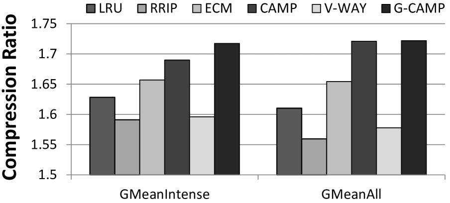
Comparison with Uncompressed Cache
Note that the overhead of using a compressed cache design is mostly due to the increased number of tags (e.g, 7.6% for BDI [185]). If the same number of bits (or even a larger number, e.g., 10%) is spent on having a larger L2 cache (i.e., a 2.2MB uncompressed L2 cache with RRIP replacement), we find that the performance is 2.8% lower than the performance of the baseline system with 2MB compressed L2 and LRU replacement, and 12.1% lower than the performance of the system with the 2MB L2 cache and G-CAMP policy. We conclude that using a compressed cache with CAMP provides a reasonable tradeoff in complexity for significantly higher performance.
4.6.2 Multi-core Results
We classify our applications into two distinct categories (homogeneous and heterogeneous) based on the distributions of the compressed sizes that they have. A homogeneous application is expected to have very few different compressed sizes for its data (when stored in the LLC). A heterogeneous application, on the other hand, has many different sizes. To formalize this classification, we first collect the access counts for different sizes for every application. Then, we mark the size with the highest access count as a “peak” and scale all other access counts with respect to this peak’s access count. If a certain size within an application has over 10% of the peak access count, it is also marked as a peak. The total number of peaks is our measure of the application’s heterogeneity with respect to block size. If the application’s number of peaks exceeds two, we classify it as heterogeneous (or simply Hetero). Otherwise, the application is considered to be homogeneous (or simply Homo). This classification matches our intuition that applications that have only one or two common sizes (e.g., one size for uncompressed blocks and one size for most of the compressed blocks) should be considered homogeneous. These two classes enable us to construct three different 2-core workload groups: (i) Homo-Homo, (ii) Homo-Hetero, and (iii) Hetero-Hetero. We generate 20 2-core workloads per group (60 total) by randomly selecting applications from different categories.
Figures 4.13(a) and 4.13(b) show the performance improvement provided by all CAMP designs as well as previously proposed designs: (i) RRIP, (ii) ECM, and (iii) V-Way over a 2MB baseline compressed cache design with LRU replacement. We draw three major conclusions.
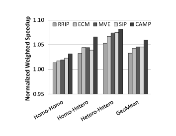
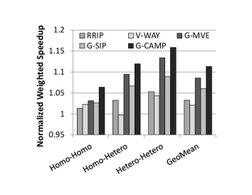
First, both G-CAMP and CAMP outperform all prior approaches in all categories. Overall, G-CAMP improves system performance by 11.3%/7.8%/6.8% over LRU/RRIP/ECM (CAMP improves by 5.9%/2.5%/1.6% over the same designs). The effect on system fairness, i.e., maximum slowdown [119, 118, 46, 55, 239] by our mechanisms is negligible.
Second, the more heterogeneity present, the higher the performance improvement with our size-aware management policies. This effect is clearly visible in both figures, and especially for global replacement policies in Figure 4.13(b). G-CAMP achieves the highest improvement (15.9% over LRU and 10.0% over RRIP) when both applications are heterogeneous, and hence there are more opportunities in size-aware replacement.
Third, when comparing relative performance of MVE vs. SIP from Figure 4.13(a) and the similar pair of G-MVE vs. G-SIP from Figure 4.13(b), we notice that in the first pair the relative performance is almost the same, while in the second pair G-MVE is significantly better than G-SIP. The primary reason for this difference is that G-MVE can get more benefit from global cache replacement, because it can easily exploit size variation between different sets. At the same time, G-SIP gets its performance improvement from the relation between the size and corresponding data reuse, which does not significantly change between local and global replacement.
We conducted a similar experiment161616We increased the LLC size to 4MB to provide the same core to cache capacity ratio as with 2-cores. with 30 4-core workloads and observe similar trends to the 2-core results presented above. G-CAMP outperforms the best prior mechanism by 8.8% on average across all workloads (by 10.2% across memory-intensive workloads).
4.6.3 Sensitivity to the Compression Algorithm
So far, we have presented results only for caches that use BDI compression [185], but as described in Section 4.2, our proposed cache management policies are applicable to different compression algorithms. We verify this by applying our mechanisms to a compressed cache design based on the FPC [10] compression algorithm. Compared to an FPC-compressed cache with LRU replacement, CAMP and G-CAMP improve performance of memory-intensive applications by 7.8% and 10.3% respectively. We conclude that our cache management policies are effective for different compression designs where they deliver the highest overall performance when compared to the state-of-the-art mechanisms.
4.6.4 SIP with Uncompressed Cache
Our SIP policy can be applied to a cache without a compressed data-store, while still using knowledge of a block’s compressibility as an indicator of reuse. We evaluate such a design to isolate the “reuse prediction” benefit of SIP independently of its benefits related to cache compression. Our single-/two-core evaluations of G-SIP show a 2.2%/3.1% performance improvement over an uncompressed LRU cache design, and a 1.3%/1.2% performance improvement over the state-of-the-art PC-based cache management mechanism [251] (evaluated as comparison to a state-of-the-art “reuse predictor”).171717 In contrast to [251], SIP does not require a special hardware table and tracking of PC with cache blocks. We conclude that using compressibility as an indicator of future reuse can improve the performance of even uncompressed caches.
4.7 Summary
In this chapter, we presented Compression-Aware Management Policies (CAMP) – a set of new and simple, yet efficient size-aware replacement policies for compressed on-chip caches. CAMP improves system performance and energy efficiency compared to three state-of-the-art cache replacement mechanisms. Our policies are based on two key observations. First, we show that direct incorporation of the compressed cache block size into replacement decisions can be a basis for a more efficient replacement policy. Second, we find that the compressed block size can be used as an indicator of a block’s future reuse in some applications. Our extensive evaluations show that CAMP, applied to modern last-level-caches (LLC), improves performance by 4.9%/9.0%/10.2% (on average for memory-intensive workloads) for single-core/two-/four-core workloads over the best state-of-the-art replacement mechanisms we evaluated. We conclude that CAMP is an efficient and low-complexity management policy for compressed caches in both single- and multi-core systems. We also hope that our observation that compressed block size indicates reuse behavior could be useful in other contexts.
Chapter 5 Main Memory Compression: Linearly Compressed Pages
5.1 Introduction
Originally published as “Linearly Compressed Pages: A Low Complexity, Low Latency Main Memory Compression Framework” in the 46th International Symposium on Microarchitecture, 2013 [184].Main memory, commonly implemented using DRAM technology, is a critical resource in modern systems. To avoid the devastating performance loss resulting from frequent page faults, main memory capacity must be sufficiently provisioned to prevent the target workload’s working set from overflowing into the orders-of-magnitude-slower backing store (e.g., hard disk or flash).
Unfortunately, the required minimum memory capacity is expected to increase in the future due to two major trends: (i) applications are generally becoming more data-intensive with increasing working set sizes, and (ii) with more cores integrated onto the same chip, more applications are running concurrently on the system, thereby increasing the aggregate working set size. Simply scaling up main memory capacity at a commensurate rate is unattractive for two reasons: (i) DRAM already constitutes a significant portion of the system’s cost and power budget [138, 153, 163], and (ii) for signal integrity reasons, today’s high frequency memory channels prevent many DRAM modules from being connected to the same channel [109], effectively limiting the maximum amount of DRAM in a system unless one resorts to expensive off-chip signaling buffers [43].
If its potential could be realized in practice, data compression would be a very attractive approach to effectively increase main memory capacity without requiring significant increases in cost or power, because a compressed piece of data can be stored in a smaller amount of physical memory. Further, such compression could be hidden from application (and most system111We assume that main memory compression is made visible to the memory management functions of the operating system (OS). In Section 5.2.3, we discuss the drawbacks of a design that makes main memory compression mostly transparent to the OS [3].) software by materializing the uncompressed data as it is brought into the processor cache. Building upon the observation that there is significant redundancy in in-memory data, previous work has proposed a variety of techniques for compressing data in caches [256, 10, 11, 264, 185, 73, 38] and in main memory [3, 57, 246, 52, 48].
5.1.1 Shortcomings of Prior Approaches
A key stumbling block to making data compression practical is that decompression lies on the critical path of accessing any compressed data. Sophisticated compression algorithms, such as Lempel-Ziv and Huffman encoding [268, 83], typically achieve high compression ratios at the expense of large decompression latencies that can significantly degrade performance. To counter this problem, prior work [264, 11, 185] on cache compression proposed specialized compression algorithms that exploit regular patterns present in in-memory data, and showed that such specialized algorithms have reasonable compression ratios compared to more complex algorithms while incurring much lower decompression latencies.
While promising, applying compression algorithms, sophisticated or simpler, to compress data stored in main memory requires first overcoming the following three challenges. First, main memory compression complicates memory management, because the operating system has to map fixed-size virtual pages to variable-size physical pages. Second, because modern processors employ on-chip caches with tags derived from the physical address to avoid aliasing between different cache lines (as physical addresses are unique, while virtual addresses are not), the cache tagging logic needs to be modified in light of memory compression to take the main memory address computation off the critical path of latency-critical L1 cache accesses. Third, in contrast with normal virtual-to-physical address translation, the physical page offset of a cache line is often different from the corresponding virtual page offset, because compressed physical cache lines are smaller than their corresponding virtual cache lines. In fact, the location of a compressed cache line in a physical page in main memory depends upon the sizes of the compressed cache lines that come before it in that same physical page. As a result, accessing a cache line within a compressed page in main memory requires an additional layer of address computation to compute the location of the cache line in main memory (which we will call the main memory address). This additional main memory address computation not only adds complexity and cost to the system, but it can also increase the latency of accessing main memory (e.g., it requires up to 22 integer addition operations in one prior design for main memory compression [57]), which in turn can degrade system performance.
While simple solutions exist for these first two challenges (as we describe later in Section 5.4), prior attempts to mitigate the performance degradation of the third challenge are either costly or inefficient [3, 57]. One approach (IBM MXT [3]) aims to reduce the number of main memory accesses, the cause of long-latency main memory address computation, by adding a large (32MB) uncompressed cache managed at the granularity at which blocks are compressed (1KB). If locality is present in the program, this approach can avoid the latency penalty of main memory address computations to access compressed data. Unfortunately, its benefit comes at a significant additional area and energy cost, and the approach is ineffective for accesses that miss in the large cache. A second approach [57] aims to hide the latency of main memory address computation by speculatively computing the main memory address of every last-level cache request in parallel with the cache access (i.e., before it is known whether or not the request needs to access main memory). While this approach can effectively reduce the performance impact of main memory address computation, it wastes a significant amount of energy (as we show in Section 5.7.3) because many accesses to the last-level cache do not result in an access to main memory.
5.1.2 Our Approach: Linearly Compressed Pages
We aim to build a main memory compression framework that neither incurs the latency penalty for memory accesses nor requires power-inefficient hardware. Our goals are: (i) having low complexity and low latency (especially when performing memory address computation for a cache line within a compressed page), (ii) being compatible with compression employed in on-chip caches (thereby minimizing the number of compressions/decompressions performed), and (iii) supporting compression algorithms with high compression ratios.
To this end, we propose a new approach to compress pages, which we call Linearly Compressed Pages (LCP). The key idea of LCP is to compress all of the cache lines within a given page to the same size. Doing so simplifies the computation of the physical address of the cache line, because the page offset is simply the product of the index of the cache line and the compressed cache line size (i.e., it can be calculated using a simple shift operation). Based on this idea, a target compressed cache line size is determined for each page. Cache lines that cannot be compressed to the target size for its page are called exceptions. All exceptions, along with the metadata required to locate them, are stored separately in the same compressed page. If a page requires more space in compressed form than in uncompressed form, then this page is not compressed. The page table indicates the form in which the page is stored.
The LCP framework can be used with any compression algorithm. We adapt two previously proposed compression algorithms (Frequent Pattern Compression (FPC) [10] and Base-Delta-Immediate Compression (BDI) [185]) to fit the requirements of LCP, and show that the resulting designs can significantly improve effective main memory capacity on a wide variety of workloads.
Note that, throughout this chapter, we assume that compressed cache lines are decompressed before being placed in the processor caches. LCP may be combined with compressed cache designs by storing compressed lines in the higher-level caches (as in [10, 185]), but the techniques are largely orthogonal, and for clarity, we present an LCP design where only main memory is compressed.222We show the results from combining main memory and cache compression in our technical report [179].
An additional, potential benefit of compressing data in main memory, which has not been fully explored by prior work on main memory compression, is memory bandwidth reduction. When data are stored in compressed format in main memory, multiple consecutive compressed cache lines can be retrieved at the cost of accessing a single uncompressed cache line. Given the increasing demand on main memory bandwidth, such a mechanism can significantly reduce the memory bandwidth requirement of applications, especially those with high spatial locality. Prior works on bandwidth compression [230, 255, 204] assumed efficient variable-length off-chip data transfers that are hard to achieve with general-purpose DRAM (e.g., DDR3 [159]). We propose a mechanism that enables the memory controller to retrieve multiple consecutive cache lines with a single access to DRAM, with negligible additional cost. Evaluations show that our mechanism provides significant bandwidth savings, leading to improved system performance.
In summary, we make the following contributions:
-
•
We propose a new main memory compression framework—Linearly Compressed Pages (LCP)—that solves the problem of efficiently computing the physical address of a compressed cache line in main memory with much lower cost and complexity than prior proposals. We also demonstrate that any compression algorithm can be adapted to fit the requirements of LCP.
- •
-
•
We evaluate the benefits of transferring compressed cache lines over the bus between DRAM and the memory controller and observe that it can considerably reduce memory bandwidth consumption (24% on average), and improve overall performance by 6.1%/13.9%/10.7% for single-/two-/four-core workloads, relative to a system without main memory compression. LCP also decreases the energy consumed by the main memory subsystem (9.5% on average over the best prior mechanism).
5.2 Background on Main Memory Compression
Data compression is widely used in storage structures to increase the effective capacity and bandwidth without significantly increasing the system cost and power consumption. One primary downside of compression is that the compressed data must be decompressed before it can be used. Therefore, for latency-critical applications, using complex dictionary-based compression algorithms [268] significantly degrades performance due to their high decompression latencies. Thus, prior work on compression of in-memory data has proposed simpler algorithms with low decompression latencies and reasonably high compression ratios, as discussed next.
5.2.1 Compressing In-Memory Data
Several studies [264, 11, 185, 10] have shown that in-memory data has exploitable patterns that allow for simpler compression techniques. Frequent value compression (FVC) [264] is based on the observation that an application’s working set is often dominated by a small set of values. FVC exploits this observation by encoding such frequently-occurring 4-byte values with fewer bits. Frequent pattern compression (FPC) [11] shows that a majority of words (4-byte elements) in memory fall under a few frequently occurring patterns. FPC compresses individual words within a cache line by encoding the frequently occurring patterns with fewer bits. Base-Delta-Immediate (BDI) compression [185] observes that, in many cases, words co-located in memory have small differences in their values. BDI compression encodes a cache line as a base-value and an array of differences that represent the deviation either from the base-value or from zero (for small values) for each word. These three low-latency compression algorithms have been proposed for on-chip caches, but can be adapted for use as part of the main memory compression framework proposed in this chapter.
5.2.2 Challenges in Memory Compression
LCP leverages the fixed-size memory pages of modern systems for the basic units of compression. However, three challenges arise from the fact that different pages (and cache lines within a page) compress to different sizes depending on data compressibility.
Challenge 1: Main Memory Page Mapping. Irregular page sizes in main memory complicate the memory management module of the operating system for two reasons (as shown in Figure 5.1). First, the operating system needs to allow mappings between the fixed-size virtual pages presented to software and the variable-size physical pages stored in main memory. Second, the operating system must implement mechanisms to efficiently handle fragmentation in main memory.
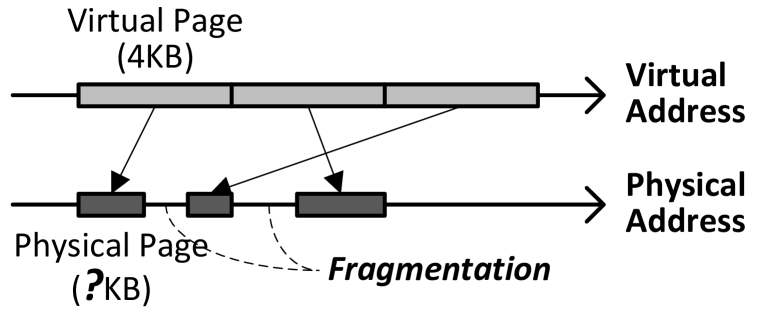
Challenge 2: Physical Address Tag Computation. On-chip caches (including L1 caches) typically employ tags derived from the physical address of the cache line to avoid aliasing, and in such systems, every cache access requires the physical address of the corresponding cache line to be computed. Hence, because the main memory addresses of the compressed cache lines differ from the nominal physical addresses of those lines, care must be taken that the computation of cache line tag does not lengthen the critical path of latency-critical L1 cache accesses.
Challenge 3: Cache Line Address Computation. When main memory is compressed, different cache lines within a page can be compressed to different sizes. The main memory address of a cache line is therefore dependent on the sizes of the compressed cache lines that come before it in the page. As a result, the processor (or the memory controller) must explicitly compute the location of a cache line within a compressed main memory page before accessing it (Figure 5.2), e.g., as in [57]. This computation not only increases complexity, but can also lengthen the critical path of accessing the cache line from both the main memory and the physically addressed cache. Note that systems that do not employ main memory compression do not suffer from this problem because the offset of a cache line within the physical page is the same as the offset of the cache line within the corresponding virtual page.
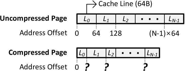
As will be seen shortly, while prior research efforts have considered subsets of these challenges, this work is the first design that provides a holistic solution to all three challenges, particularly Challenge 3, with low latency and low (hardware and software) complexity.
5.2.3 Prior Work on Memory Compression
Of the many prior works on using compression for main memory (e.g., [3, 57, 246, 111, 48, 52, 204]), two in particular are the most closely related to the design proposed in this chapter, because both of them are mostly hardware designs. We describe these two designs along with their shortcomings.
Tremaine et al. [233] proposed a memory controller design, Pinnacle, based on IBM’s Memory Extension Technology (MXT) [3] that employed Lempel-Ziv compression [268] to manage main memory. To address the three challenges described above, Pinnacle employs two techniques. First, Pinnacle internally uses a 32MB last level cache managed at a 1KB granularity, same as the granularity at which blocks are compressed. This cache reduces the number of accesses to main memory by exploiting locality in access patterns, thereby reducing the performance degradation due to the address computation (Challenge 3). However, there are several drawbacks to this technique: (i) such a large cache adds significant area and energy costs to the memory controller, (ii) the approach requires the main memory address computation logic to be present and used when an access misses in the 32MB cache, and (iii) if caching is not effective (e.g., due to lack of locality or larger-than-cache working set sizes), this approach cannot reduce the performance degradation due to main memory address computation. Second, to avoid complex changes to the operating system and on-chip cache-tagging logic, Pinnacle introduces a real address space between the virtual and physical address spaces. The real address space is uncompressed and is twice the size of the actual available physical memory. The operating system maps virtual pages to same-size pages in the real address space, which addresses Challenge 1. On-chip caches are tagged using the real address (instead of the physical address, which is dependent on compressibility), which effectively solves Challenge 2. On a miss in the 32MB cache, Pinnacle maps the corresponding real address to the physical address of the compressed block in main memory, using a memory-resident mapping-table managed by the memory controller. Following this, Pinnacle retrieves the compressed block from main memory, performs decompression and sends the data back to the processor. Clearly, the additional access to the memory-resident mapping table on every cache miss significantly increases the main memory access latency. In addition to this, Pinnacle’s decompression latency, which is on the critical path of a memory access, is 64 processor cycles.
Ekman and Stenström [57] proposed a main memory compression design to address the drawbacks of MXT. In their design, the operating system maps the uncompressed virtual address space directly to a compressed physical address space. To compress pages, they use a variant of the Frequent Pattern Compression technique [10, 11], which has a much smaller decompression latency (5 cycles) than the Lempel-Ziv compression in Pinnacle (64 cycles). To avoid the long latency of a cache line’s main memory address computation (Challenge 3), their design overlaps this computation with the last-level (L2) cache access. For this purpose, their design extends the page table entries to store the compressed sizes of all the lines within the page. This information is loaded into a hardware structure called the Block Size Table (BST). On an L1 cache miss, the BST is accessed in parallel with the L2 cache to compute the exact main memory address of the corresponding cache line. While the proposed mechanism reduces the latency penalty of accessing compressed blocks by overlapping main memory address computation with L2 cache access, the main memory address computation is performed on every L2 cache access (as opposed to only on L2 cache misses in LCP). This leads to significant wasted work and additional power consumption. Even though BST has the same number of entries as the translation lookaside buffer (TLB), its size is at least twice that of the TLB [57]. This adds to the complexity and power consumption of the system significantly. To address Challenge 1, the operating system uses multiple pools of fixed-size physical pages. This reduces the complexity of managing physical pages at a fine granularity. Ekman and Stenstrom [57] do not address Challenge 2.
In summary, prior work on hardware-based main memory compression mitigate the performance degradation due to the main memory address computation problem (Challenge 3) by either adding large hardware structures that consume significant area and power [3] or by using techniques that require energy-inefficient hardware and lead to wasted energy [57].
5.3 Linearly Compressed Pages
In this section, we provide the basic idea and a brief overview of our proposal, Linearly Compressed Pages (LCP), which overcomes the aforementioned shortcomings of prior proposals. Further details will follow in Section 5.4.
5.3.1 LCP: Basic Idea
The main shortcoming of prior approaches to main memory compression is that different cache lines within a physical page can be compressed to different sizes based on the compression scheme. As a result, the location of a compressed cache line within a physical page depends on the sizes of all the compressed cache lines before it in the same page. This requires the memory controller to explicitly perform this complex calculation (or cache the mapping in a large, energy-inefficient structure) in order to access the line.
To address this shortcoming, we propose a new approach to compressing pages, called the Linearly Compressed Page (LCP). The key idea of LCP is to use a fixed size for compressed cache lines within a given page (alleviating the complex and long-latency main memory address calculation problem that arises due to variable-size cache lines), and yet still enable a page to be compressed even if not all cache lines within the page can be compressed to that fixed size (enabling high compression ratios).
Because all the cache lines within a given page are compressed to the same size, the location of a compressed cache line within the page is simply the product of the index of the cache line within the page and the size of the compressed cache line—essentially a linear scaling using the index of the cache line (hence the name Linearly Compressed Page). LCP greatly simplifies the task of computing a cache line’s main memory address. For example, if all cache lines within a page are compressed to bytes, the byte offset of the third cache line (index within the page is 2) from the start of the physical page is , if the line is compressed. This computation can be implemented as a simple shift operation.
Figure 5.3 shows the organization of an example Linearly Compressed Page, based on the ideas described above. In this example, we assume that a virtual page is 4KB, an uncompressed cache line is 64B, and the target compressed cache line size is 16B.
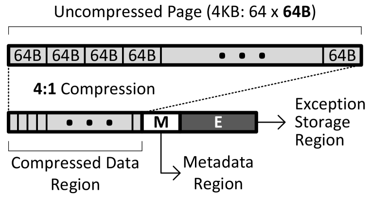
As shown in the figure, the LCP contains three distinct regions. The first region, the compressed data region, contains a 16-byte slot for each cache line in the virtual page. If a cache line is compressible, the corresponding slot stores the compressed version of the cache line. However, if the cache line is not compressible, the corresponding slot is assumed to contain invalid data. In our design, we refer to such an incompressible cache line as an “exception”. The second region, metadata, contains all the necessary information to identify and locate the exceptions of a page. We provide more details on what exactly is stored in the metadata region in Section 5.4.2. The third region, the exception storage, is the place where all the exceptions of the LCP are stored in their uncompressed form. Our LCP design allows the exception storage to contain unused space. In other words, not all entries in the exception storage may store valid exceptions. As we will describe in Section 5.4, this enables the memory controller to use the unused space for storing future exceptions, and also simplifies the operating system page management mechanism.
Next, we will provide a brief overview of the main memory compression framework we build using LCP.
5.3.2 LCP Operation
Our LCP-based main memory compression framework consists of components that handle three key issues: (i) page compression, (ii) cache line reads from main memory, and (iii) cache line writebacks into main memory. Figure 5.4 shows the high-level design and operation.
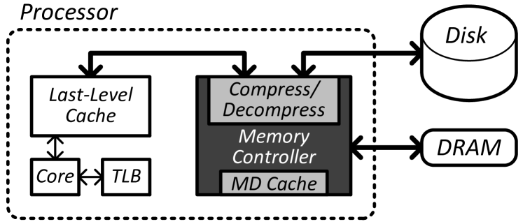
Page Compression. When a page is accessed for the first time from disk, the operating system (with the help of the memory controller) first determines whether the page is compressible using the compression algorithm employed by the framework (described in Section 5.4.7). If the page is compressible, the OS allocates a physical page of appropriate size and stores the compressed page (LCP) in the corresponding location. It also updates the relevant portions of the corresponding page table mapping to indicate (i) whether the page is compressed, and if so, (ii) the compression scheme used to compress the page (details in Section 5.4.1).
Cache Line Read. When the memory controller receives a read request for a cache line within an LCP, it must find and decompress the data. Multiple design solutions are possible to perform this task efficiently. A naïve way of reading a cache line from an LCP would require at least two accesses to the corresponding page in main memory. First, the memory controller accesses the metadata in the LCP to determine whether the cache line is stored in the compressed format. Second, based on the result, the controller either (i) accesses the cache line from the compressed data region and decompresses it, or (ii) accesses it uncompressed from the exception storage.
To avoid two accesses to main memory, we propose two optimizations that enable the controller to retrieve the cache line with the latency of just one main memory access in the common case. First, we add a small metadata (MD) cache to the memory controller that caches the metadata of the recently accessed LCPs—the controller avoids the first main memory access to the metadata in cases when the metadata is present in the MD cache. Second, in cases when the metadata is not present in the metadata cache, the controller speculatively assumes that the cache line is stored in the compressed format and first accesses the data corresponding to the cache line from the compressed data region. The controller then overlaps the latency of the cache line decompression with the access to the metadata of the LCP. In the common case, when the speculation is correct (i.e., the cache line is actually stored in the compressed format), this approach significantly reduces the latency of serving the read request. In the case of a misspeculation (uncommon case), the memory controller issues another request to retrieve the cache line from the exception storage.
Cache Line Writeback. If the memory controller receives a request for a cache line writeback, it then attempts to compress the cache line using the compression scheme associated with the corresponding LCP. Depending on the original state of the cache line (compressible or incompressible), there are four different possibilities: the cache line (1) was compressed and stays compressed, (2) was uncompressed and stays uncompressed, (3) was uncompressed but becomes compressed, and (4) was compressed but becomes uncompressed. In the first two cases, the memory controller simply overwrites the old data with the new data at the same location associated with the cache line. In case 3, the memory controller frees the exception storage slot for the cache line and writes the compressible data in the compressed data region of the LCP. (Section 5.4.2 provides more details on how the exception storage is managed.) In case 4, the memory controller checks whether there is enough space in the exception storage region to store the uncompressed cache line. If so, it stores the cache line in an available slot in the region. If there are no free exception storage slots in the exception storage region of the page, the memory controller traps to the operating system, which migrates the page to a new location (which can also involve page recompression). In both cases 3 and 4, the memory controller appropriately modifies the LCP metadata associated with the cache line’s page.
Note that in the case of an LLC writeback to main memory (and assuming that TLB information is not available at the LLC), the cache tag entry is augmented with the same bits that are used to augment page table entries. Cache compression mechanisms, e.g., FPC [10] and BDI [185], already have the corresponding bits for encoding, so that the tag size overhead is minimal when main memory compression is used together with cache compression.
5.4 Detailed Design
In this section, we provide a detailed description of LCP, along with the changes to the memory controller, operating system and on-chip cache tagging logic. In the process, we explain how our proposed design addresses each of the three challenges (Section 5.2.2).
5.4.1 Page Table Entry Extension
To keep track of virtual pages that are stored in compressed format in main memory, the page table entries need to be extended to store information related to compression (Figure 5.5). In addition to the information already maintained in the page table entries (such as the base address for a corresponding physical page, p-base), each virtual page in the system is associated with the following pieces of metadata: (i) c-bit, a bit that indicates if the page is mapped to a compressed physical page (LCP), (ii) c-type, a field that indicates the compression scheme used to compress the page, (iii) c-size, a field that indicates the size of the LCP, and (iv) c-base, a p-base extension that enables LCPs to start at an address not aligned with the virtual page size. The number of bits required to store c-type, c-size and c-base depends on the exact implementation of the framework. In the implementation we evaluate, we assume 3 bits for c-type (allowing 8 possible different compression encodings), 2 bits for c-size (4 possible page sizes: 512B, 1KB, 2KB, 4KB), and 3 bits for c-base (at most eight 512B compressed pages can fit into a 4KB uncompressed slot). Note that existing systems usually have enough unused bits (up to 15 bits in Intel x86-64 systems [91]) in their PTE entries that can be used by LCP without increasing the PTE size.

When a virtual page is compressed (the c-bit is set), all the compressible cache lines within the page are compressed to the same size, say . The value of is uniquely determined by the compression scheme used to compress the page, i.e., the c-type (Section 5.4.7 discusses determining the c-type for a page). We next describe the LCP organization in more detail.
5.4.2 LCP Organization
We will discuss each of an LCP’s three regions in turn. We begin by defining the following symbols: is the virtual page size of the system (e.g., 4KB); is the uncompressed cache line size (e.g., 64B);333 Large pages (e.g., 4MB or 1GB) can be supported with LCP through minor modifications that include scaling the corresponding sizes of the metadata and compressed data regions. The exception area metadata keeps the exception index for every cache line on a compressed page. This metadata can be partitioned into multiple 64-byte cache lines that can be handled similar to 4KB pages. The exact “metadata partition” can be easily identified based on the cache line index within a page. is the number of cache lines per virtual page (e.g., 64); and is the size of LCP’s metadata region. In addition, on a per-page basis, we define to be the compressed physical page size; to be the compressed cache line size; and to be the number of slots available for exceptions.
Compressed Data Region
The compressed data region is a contiguous array of slots each of size . Each one of the cache lines in the virtual page is mapped to one of the slots, irrespective of whether the cache line is compressible or not. Therefore, the size of the compressed data region is . This organization simplifies the computation required to determine the main memory address for the compressed slot corresponding to a cache line. More specifically, the address of the compressed slot for the cache line can be computed as , where the first two terms correspond to the start of the LCP (m-size equals to the minimum page size, 512B in our implementation) and the third indicates the offset within the LCP of the compressed slot (see Figure 5.6). Thus, computing the main memory address of a compressed cache line requires one multiplication (can be implemented as a shift) and two additions independent of (fixed latency). This computation requires a lower latency and simpler hardware than prior approaches (e.g., up to 22 additions in the design proposed in [57]), thereby efficiently addressing Challenge 3 (cache line address computation).

Metadata Region
The metadata region of an LCP contains two parts (Figure 5.7). The first part stores two pieces of information for each cache line in the virtual page: (i) a bit indicating whether the cache line is incompressible, i.e., whether the cache line is an exception, e-bit, and (ii) the index of the cache line in the exception storage, e-index. If the e-bit is set for a cache line, then the corresponding cache line is stored uncompressed in location e-index in the exception storage. The second part of the metadata region is a valid bit (v-bit) vector to track the state of the slots in the exception storage. If a v-bit is set, it indicates that the corresponding slot in the exception storage is used by some uncompressed cache line within the page.
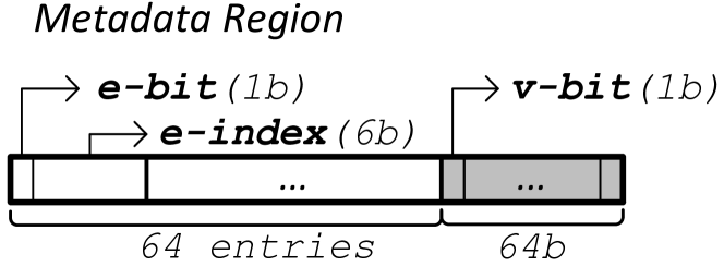
The size of the first part depends on the size of e-index, which in turn depends on the number of exceptions allowed per page. Because the number of exceptions cannot exceed the number of cache lines in the page (), we will need at most bits for each cache line in the first part of the metadata. For the same reason, we will need at most bits in the bit vector in the second part of the metadata. Therefore, the size of the metadata region is given by . Since is fixed for the entire system, the size of the metadata region () is the same for all compressed pages (64B in our implementation).
Exception Storage Region
The third region, the exception storage, is the place where all incompressible
cache lines of the page are stored. If a cache line is present in the
location e-index in the exception storage, its main memory address
can be computed as:
.
The number of slots available in the
exception storage () is dictated by the size of the compressed physical
page allocated by the operating system for the corresponding LCP. The
following equation expresses the relation between the physical page size
(), the compressed cache line size () that is determined by
c-type, and the number of available slots in the exception storage ():
| (5.1) |
As mentioned before, the metadata region contains a bit vector that is used to manage the exception storage. When the memory controller assigns an exception slot to an incompressible cache line, it sets the corresponding bit in the bit vector to indicate that the slot is no longer free. If the cache line later becomes compressible and no longer requires the exception slot, the memory controller resets the corresponding bit in the bit vector. In the next section, we describe the operating system memory management policy that determines the physical page size () allocated for an LCP, and hence, the number of available exception slots ().
5.4.3 Operating System Memory Management
The first challenge related to main memory compression is to provide operating system support for managing variable-size compressed physical pages – i.e., LCPs. Depending on the compression scheme employed by the framework, different LCPs may be of different sizes. Allowing LCPs of arbitrary sizes would require the OS to keep track of main memory at a very fine granularity. It could also lead to fragmentation across the entire main memory at a fine granularity. As a result, the OS would need to maintain large amounts of metadata to maintain the locations of individual pages and the free space, which would also lead to increased complexity.
To avoid this problem, our mechanism allows the OS to manage main memory using a fixed number of pre-determined physical page sizes – e.g., 512B, 1KB, 2KB, 4KB (a similar approach was proposed in [27] to address the memory allocation problem). For each one of the chosen sizes, the OS maintains a pool of allocated pages and a pool of free pages. When a page is compressed for the first time or recompressed due to overflow (described in Section 5.4.6), the OS chooses the smallest available physical page size that fits the compressed page. For example, if a page is compressed to 768B, then the OS allocates a physical page of size 1KB. For a page with a given size, the available number of exceptions for the page, , can be determined using Equation 5.1.
5.4.4 Changes to the Cache Tagging Logic
As mentioned in Section 5.2.2, modern systems employ physically-tagged caches to avoid aliasing problems. However, in a system that employs main memory compression, using the physical (main memory) address to tag cache lines puts the main memory address computation on the critical path of L1 cache access (Challenge 2). To address this challenge, we modify the cache tagging logic to use the tuple physical page base address, cache line index within the page for tagging cache lines. This tuple maps to a unique cache line in the system, and hence avoids aliasing problems without requiring the exact main memory address to be computed. The additional index bits are stored within the cache line tag.
5.4.5 Changes to the Memory Controller
In addition to the changes to the memory controller operation described in Section 5.3.2, our LCP-based framework requires two hardware structures to be added to the memory controller: (i) a small metadata cache to accelerate main memory lookups in LCP, and (ii) compression/decompression hardware to perform the compression and decompression of cache lines.
Metadata Cache
As described in Section 5.3.2, a small metadata cache in the memory controller enables our approach, in the common case, to retrieve a compressed cache block in a single main memory access. This cache stores the metadata region of recently accessed LCPs so that the metadata for subsequent accesses to such recently-accessed LCPs can be retrieved directly from the cache. In our study, we find that a small 512-entry metadata cache (32KB444We evaluated the sensitivity of performance to MD cache size and find that 32KB is the smallest size that enables our design to avoid most of the performance loss due to additional metadata accesses.) can service 88% of the metadata accesses on average across all our workloads. Some applications have lower hit rate, especially sjeng and astar [217]. An analysis of these applications reveals that their memory accesses exhibit very low locality. As a result, we also observed a low TLB hit rate for these applications. Because TLB misses are costlier than MD cache misses (the former requires multiple memory accesses), the low MD cache hit rate does not lead to significant performance degradation for these applications.
We expect the MD cache power to be much lower than the power consumed by other on-chip structures (e.g., L1 caches), because the MD cache is accessed much less frequently (hits in any on-chip cache do not lead to an access to the MD cache).
Compression/Decompression Hardware
Depending on the compression scheme employed with our LCP-based framework, the memory controller should be equipped with the hardware necessary to compress and decompress cache lines using the corresponding scheme. Although our framework does not impose any restrictions on the nature of the compression algorithm, it is desirable to have compression schemes that have low complexity and decompression latency – e.g., Frequent Pattern Compression (FPC) [10] and Base-Delta-Immediate Compression (BDI) [185]. In Section 5.4.7, we provide more details on how to adapt any compression algorithm to fit the requirements of LCP and also the specific changes we made to FPC and BDI as case studies of compression algorithms that we adapted to the LCP framework.
5.4.6 Handling Page Overflows
As described in Section 5.3.2, when a cache line is written back to main memory, the cache line may switch from being compressible to being incompressible. When this happens, the memory controller should explicitly find a slot in the exception storage for the uncompressed cache line. However, it is possible that all the slots in the exception storage are already used by other exceptions in the LCP. We call this scenario a page overflow. A page overflow increases the size of the LCP and leads to one of two scenarios: (i) the LCP still requires a physical page size that is smaller than the uncompressed virtual page size (type-1 page overflow), and (ii) the LCP now requires a physical page size that is larger than the uncompressed virtual page size (type-2 page overflow).
Type-1 page overflow simply requires the operating system to migrate the LCP to a physical page of larger size (without recompression). The OS first allocates a new page and copies the data from the old location to the new location. It then modifies the mapping for the virtual page to point to the new location. While in transition, the page is locked, so any memory request to this page is delayed. In our evaluations, we stall the application for 20,000 cycles555 To fetch a 4KB page, we need to access 64 cache lines (64 bytes each). In the worst case, this will lead to 64 accesses to main memory, most of which are likely to be DRAM row-buffer hits. Since a row-buffer hit takes 7.5ns, the total time to fetch the page is 495ns. On the other hand, the latency penalty of two context-switches (into the OS and out of the OS) is around 4us [142]. Overall, a type-1 overflow takes around 4.5us. For a 4.4Ghz or slower processor, this is less than 20,000 cycles. when a type-1 overflow occurs; we also find that (on average) type-1 overflows happen less than once per two million instructions. We vary this latency between 10,000–100,000 cycles and observe that the benefits of our framework (e.g., bandwidth compression) far outweigh the overhead due to type-1 overflows.
In a type-2 page overflow, the size of the LCP exceeds the uncompressed virtual page size. Therefore, the OS attempts to recompress the page, possibly using a different encoding (c-type). Depending on whether the page is compressible or not, the OS allocates a new physical page to fit the LCP or the uncompressed page, and migrates the data to the new location. The OS also appropriately modifies the c-bit, c-type and the c-base in the corresponding page table entry. Clearly, a type-2 overflow requires more work from the OS than a type-1 overflow. However, we expect page overflows of type-2 to occur rarely. In fact, we never observed a type-2 overflow in our evaluations.
Avoiding Recursive Page Faults
There are two types of pages that require special consideration: (i) pages that keep internal OS data structures, e.g., pages containing information required to handle page faults, and (ii) shared data pages that have more than one page table entry (PTE) mapping to the same physical page. Compressing pages of the first type can potentially lead to recursive page fault handling. The problem can be avoided if the OS sets a special do not compress bit, e.g., as a part of the page compression encoding, so that the memory controller does not compress these pages. The second type of pages (shared pages) require consistency across multiple page table entries, such that when one PTE’s compression information changes, the second entry is updated as well. There are two possible solutions to this problem. First, as with the first type of pages, these pages can be marked as do not compress. Second, the OS could maintain consistency of the shared PTEs by performing multiple synchronous PTE updates (with accompanying TLB shootdowns). While the second solution can potentially lead to better average compressibility, the first solution (used in our implementation) is simpler and requires minimal changes inside the OS.
Another situation that can potentially lead to a recursive fault is the eviction of dirty cache lines from the LLC to DRAM due to some page overflow handling that leads to another overflow. In order to solve this problem, we assume that the memory controller has a small dedicated portion of the main memory that is used as a scratchpad to store cache lines needed to perform page overflow handling. Dirty cache lines that are evicted from LLC to DRAM due to OS overflow handling are stored in this buffer space. The OS is responsible to minimize the memory footprint of the overflow handler. Note that this situation is expected to be very rare in practice, because even a single overflow is infrequent.
Handling Special Cases
There are several types of scenarios that require special attention: (i) rapid changes in compressibility (e.g., highly compressed page overwritten with non-compressible data), (ii) multiple back-to-back page overflows. The first scenario leads to the increase in the number of page overflows that are costly and time-consuming. This situation is common when the page is initialized with some values (frequently zero values), and then after some period of time multiple updates (e.g., writebacks) bring completely different data into this page. For zero pages the solution is simply not storing them at all - only one bit in TLB buffer, until there are not enough writebacks happen to these page to estimate its compressibility. For other pages, especially the ones that are allocated (e.g., through malloc), but never been updated, we also delay compression until there is not enough evidence that this page can be successfully compressed. These simple optimizations allow us to avoid major sources of the page overflows.
The second scenario, while possible in practice, was extremely rare in our experiments. Nevertheless, one possible solution we consider to this problem, is to detect the situations like this, and when the number of back to back page overflows exceeds certain threshold, start to decompress this applications’ data in the background to avoid further overflows.
5.4.7 Compression Algorithms
Our LCP-based main memory compression framework can be employed with any compression algorithm. In this section, we describe how to adapt a generic compression algorithm to fit the requirements of the LCP framework. Subsequently, we describe how to adapt the two compression algorithms used in our evaluation.
Adapting a Compression Algorithm to Fit LCP
Every compression scheme is associated with a compression function, , and a decompression function, . To compress a virtual page into the corresponding LCP using the compression scheme, the memory controller carries out three steps. In the first step, the controller compresses every cache line in the page using and feeds the sizes of each compressed cache line to the second step. In the second step, the controller computes the total compressed page size (compressed data + metadata + exceptions, using the formulas from Section 5.4.2) for each of a fixed set of target compressed cache line sizes and selects a target compressed cache line size that minimizes the overall LCP size. In the third and final step, the memory controller classifies any cache line whose compressed size is less than or equal to the target size as compressible and all other cache lines as incompressible (exceptions). The memory controller uses this classification to generate the corresponding LCP based on the organization described in Section 5.3.1.
To decompress a compressed cache line of the page, the memory controller reads the fixed-target-sized compressed data and feeds it to the hardware implementation of function .
FPC and BDI Compression Algorithms
Although any compression algorithm can be employed with our framework using the approach described above, it is desirable to use compression algorithms that have low complexity hardware implementation and low decompression latency, so that the overall complexity and latency of the design are minimized. For this reason, we adapt to fit our LCP framework two state-of-the-art compression algorithms that achieve such design points in the context of compressing in-cache data: (i) Frequent Pattern Compression [10], and (ii) Base-Delta-Immediate Compression [185].
Frequent Pattern Compression (FPC) is based on the observation that a majority of the words accessed by applications fall under a small set of frequently occurring patterns [11]. FPC compresses each cache line one word at a time. Therefore, the final compressed size of a cache line is dependent on the individual words within the cache line. To minimize the time to perform the compression search procedure described in Section 5.4.7, we limit the search to four different target cache line sizes: 16B, 21B, 32B and 44B (similar to the fixed sizes used in [57]).
Base-Delta-Immediate (BDI) Compression is based on the observation that in most cases, words co-located in memory have small differences in their values, a property referred to as low dynamic range [185]. BDI encodes cache lines with such low dynamic range using a base value and an array of differences (s) of words within the cache line from either the base value or from zero. The size of the final compressed cache line depends only on the size of the base and the size of the s. To employ BDI within our framework, the memory controller attempts to compress a page with different versions of the Base-Delta encoding as described by Pekhimenko et al. [185] and then chooses the combination that minimizes the final compressed page size (according to the search procedure in Section 5.4.7).
5.5 LCP Optimizations
In this section, we describe two simple optimizations to our proposed LCP-based framework: (i) memory bandwidth reduction via compressed cache lines, and (ii) exploiting zero pages and cache lines for higher bandwidth utilization.
5.5.1 Enabling Memory Bandwidth Reduction
One potential benefit of main memory compression that has not been examined in detail by prior work on memory compression is bandwidth reduction.666Prior work [64, 255, 230, 204] looked at the possibility of using compression for bandwidth reduction between the memory controller and DRAM. While significant reduction in bandwidth consumption is reported, prior work achieve this reduction either at the cost of increased memory access latency [64, 255, 230], as they have to both compress and decompress a cache line for every request, or based on a specialized main memory design [204], e.g., GDDR3 [87]. When cache lines are stored in compressed format in main memory, multiple consecutive compressed cache lines can be retrieved at the cost of retrieving a single uncompressed cache line. For example, when cache lines of a page are compressed to 1/4 their original size, four compressed cache lines can be retrieved at the cost of a single uncompressed cache line access. This can significantly reduce the bandwidth requirements of applications, especially those with good spatial locality. We propose two mechanisms that exploit this idea.
In the first mechanism, when the memory controller needs to access a cache line in the compressed data region of LCP, it obtains the data from multiple consecutive compressed slots (which add up to the size of an uncompressed cache line). However, some of the cache lines that are retrieved in this manner may not be valid. To determine if an additionally-fetched cache line is valid or not, the memory controller consults the metadata corresponding to the LCP. If a cache line is not valid, then the corresponding data is not decompressed. Otherwise, the cache line is decompressed and then stored in the cache.
The second mechanism is an improvement over the first mechanism, where the memory controller additionally predicts if the additionally-fetched cache lines are useful for the application. For this purpose, the memory controller uses hints from a multi-stride prefetcher [89]. In this mechanism, if the stride prefetcher suggests that an additionally-fetched cache line is part of a useful stream, then the memory controller stores that cache line in the cache. This approach has the potential to prevent cache lines that are not useful from polluting the cache. Section 5.7.5 shows the effect of this approach on both performance and bandwidth consumption.
Note that prior work [64, 255, 230, 204] assumed that when a cache line is compressed, only the compressed amount of data can be transferred over the DRAM bus, thereby freeing the bus for the future accesses. Unfortunately, modern DRAM chips are optimized for full cache block accesses [259], so they would need to be modified to support such smaller granularity transfers. Our proposal does not require modifications to DRAM itself or the use of specialized DRAM such as GDDR3 [87].
5.5.2 Zero Pages and Zero Cache Lines
Prior work [54, 256, 10, 57, 185] observed that in-memory data contains a significant number of zeros at two granularities: all-zero pages and all-zero cache lines. Because this pattern is quite common, we propose two changes to the LCP framework to more efficiently compress such occurrences of zeros. First, one value of the page compression encoding (e.g., c-type of 0) is reserved to indicate that the entire page is zero. When accessing data from a page with c-type , the processor can avoid any LLC or DRAM access by simply zeroing out the allocated cache line in the L1-cache. Second, to compress all-zero cache lines more efficiently, we can add another bit per cache line to the first part of the LCP metadata. This bit, which we call the z-bit, indicates if the corresponding cache line is zero. Using this approach, the memory controller does not require any main memory access to retrieve a cache line with the z-bit set (assuming a metadata cache hit).
5.6 Methodology
| CPU Processor | 1–4 cores, 4GHz, x86 in-order |
|---|---|
| CPU L1-D cache | 32KB, 64B cache-line, 2-way, 1 cycle |
| CPU L2 cache | 2 MB, 64B cache-line, 16-way, 20 cycles |
| Main memory | 2 GB, 4 Banks, 8 KB row buffers, |
| 1 memory channel, DDR3-1066 [159] | |
| LCP Design | Type-1 Overflow Penalty: 20,000 cycles |
Our evaluations use an in-house, event-driven 32-bit x86 simulator whose front-end is based on Simics [154]. All configurations have private L1 caches and shared L2 caches. Major simulation parameters are provided in Table 5.1. We use benchmarks from the SPEC CPU2006 suite [217], four TPC-H/TPC-C queries [232], and an Apache web server. All results are collected by running a representative portion (based on PinPoints [173]) of the benchmarks for 1 billion instructions. We build our energy model based on McPat [143], CACTI [229], C-Pack [38], and the Synopsys Design Compiler with 65nm library (to evaluate the energy of compression/decompression with BDI and address calculation in [57]).
Metrics. We measure the performance of our benchmarks using IPC (instruction per cycle) and effective compression ratio (effective DRAM size increase, e.g., a compression ratio of 1.5 for 2GB DRAM means that the compression scheme achieves the size benefits of a 3GB DRAM). For multi-programmed workloads we use the weighted speedup [216] performance metric: (). For bandwidth consumption we use BPKI (bytes transferred over bus per thousand instructions [218]).
Parameters of the Evaluated Schemes. As reported in the respective previous works, we used a decompression latency of 5 cycles for FPC and 1 cycle for BDI.
5.7 Results
In our experiments for both single-core and multi-core systems, we compare five different designs that employ different main memory compression strategies (frameworks) and different compression algorithms: (i) Baseline system with no compression, (ii) robust main memory compression (RMC-FPC) [57], (iii) and (iv) LCP framework with both FPC and BDI compression algorithms (LCP-FPC and LCP-BDI), and (v) MXT [3]. Note that it is fundamentally possible to build a RMC-BDI design as well, but we found that it leads to either low energy efficiency (due to an increase in the BST metadata table entry size [57] with many more encodings in BDI) or low compression ratio (when the number of encodings is artificially decreased). Hence, for brevity, we exclude this potential design from our experiments.
In addition, we evaluate two hypothetical designs: Zero Page Compression (ZPC) and Lempel-Ziv (LZ)777Our implementation of LZ performs compression at 4KB page-granularity and serves as an idealized upper bound for the in-memory compression ratio. In contrast, MXT employs Lempel-Ziv at 1KB granularity. to show some practical upper bounds on main memory compression. Table 7.1 summarizes all the designs.
| Name | Framework | Compression Algorithm |
| Baseline | None | None |
| RMC-FPC | RMC [57] | FPC [10] |
| LCP-FPC | LCP | FPC [10] |
| LCP-BDI | LCP | BDI [185] |
| MXT | MXT [3] | Lempel-Ziv [268] |
| ZPC | None | Zero Page Compression |
| LZ | None | Lempel-Ziv [268] |
5.7.1 Effect on DRAM Capacity
Figure 5.8 compares the compression ratio of all the designs described in Table 7.1. We draw two major conclusions. First, as expected, MXT, which employs the complex LZ algorithm, has the highest average compression ratio (2.30) of all practical designs and performs closely to our idealized LZ implementation (2.60). At the same time, LCP-BDI provides a reasonably high compression ratio (1.62 on average), outperforming RMC-FPC (1.59), and LCP-FPC (1.52). (Note that LCP could be used with both BDI and FPC algorithms together, and the average compression ratio in this case is as high as 1.69.)
Second, while the average compression ratio of ZPC is relatively low (1.29), it greatly improves the effective memory capacity for a number of applications (e.g., GemsFDTD, zeusmp, and cactusADM). This justifies our design decision of handling zero pages at the TLB-entry level. We conclude that our LCP framework achieves the goal of high compression ratio.
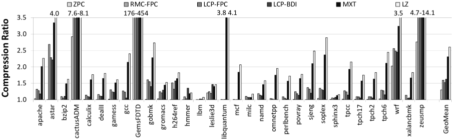
Distribution of Compressed Pages
The primary reason why applications have different compression ratios is the redundancy difference in their data. This leads to the situation where every application has its own distribution of compressed pages with different sizes (0B, 512B, 1KB, 2KB, 4KB). Figure 5.9 shows these distributions for the applications in our study when using the LCP-BDI design. As we can see, the percentage of memory pages of every size in fact significantly varies between the applications, leading to different compression ratios (shown in Figure 5.8). For example, cactusADM has a high compression ratio due to many 0B and 512B pages (there is a significant number of zero cache lines in its data), while astar and h264ref get most of their compression with 2KB pages due to cache lines with low dynamic range [185].
Compression Ratio over Time
To estimate the efficiency of LCP-based compression over time, we conduct an experiment where we measure the compression ratios of our applications every 100 million instructions (for a total period of 5 billion instructions). The key observation we make is that the compression ratio for most of the applications is stable over time (the difference between the highest and the lowest ratio is within 10%). Figure 5.10 shows all notable outliers from this observation: astar, cactusADM, h264ref, and zeusmp. Even for these applications, the compression ratio stays relatively constant for a long period of time, although there are some noticeable fluctuations in compression ratio (e.g., for astar at around 4 billion instructions, for cactusADM at around 500M instructions). We attribute this behavior to a phase change within an application that sometimes leads to changes in the applications’ data. Fortunately, these cases are infrequent and do not have a noticeable effect on the application’s performance (as we describe in Section 5.7.2). We conclude that the capacity benefits provided by the LCP-based frameworks are usually stable over long periods of time.
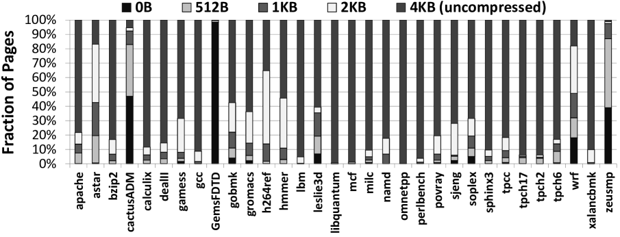
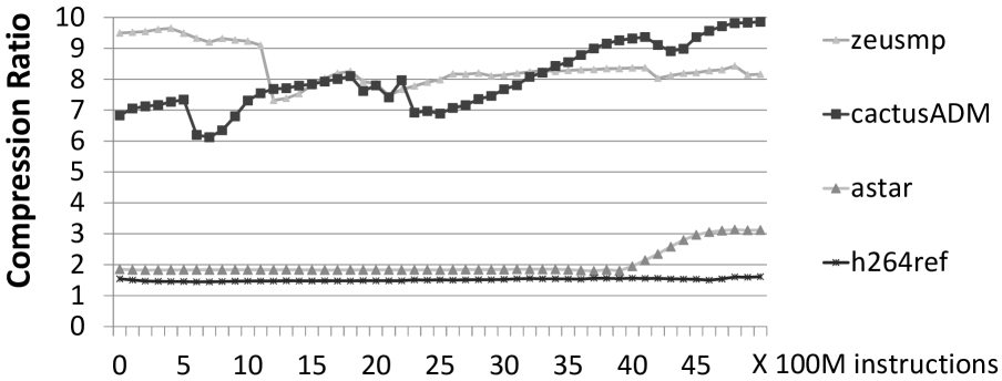
5.7.2 Effect on Performance
Main memory compression can improve performance in two major ways: (i) reduced memory bandwidth requirements, which can enable less contention on the main memory bus, an increasingly important bottleneck in systems, and (ii) reduced memory footprint, which can reduce long-latency disk accesses. We evaluate the performance improvement due to memory bandwidth reduction (including our optimizations for compressing zero values described in Section 5.5.2) in Sections 5.7.2 and 5.7.2. We also evaluate the decrease in page faults in Section 5.7.2.
Single-Core Results
Figure 7.1 shows the performance of single-core workloads using three key evaluated designs (RMC-FPC, LCP-FPC, and LCP-BDI) normalized to the Baseline. Compared against an uncompressed system (Baseline), the LCP-based designs (LCP-BDI and LCP-FPC) improve performance by 6.1%/5.2% and also outperform RMC-FPC.888Note that in order to provide a fair comparison, we enhanced the RMC-FPC approach with the same optimizations we did for LCP, e.g., bandwidth compression. The original RMC-FPC design reported an average degradation in performance [57]. We conclude that our LCP framework is effective in improving performance by compressing main memory.
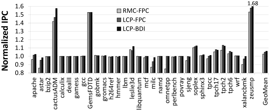
Note that LCP-FPC outperforms RMC-FPC (on average) despite having a slightly lower compression ratio. This is mostly due to the lower overhead when accessing metadata information (RMC-FPC needs two memory accesses to different main memory pages in the case of a BST table miss, while LCP-based framework performs two accesses to the same main memory page that can be pipelined). This is especially noticeable in several applications, e.g., astar, milc, and xalancbmk that have low metadata table (BST) hit rates (LCP can also degrade performance for these applications). We conclude that our LCP framework is more effective in improving performance than RMC [57].
Multi-Core Results
When the system has a single core, the memory bandwidth pressure may not be large enough to take full advantage of the bandwidth benefits of main memory compression. However, in a multi-core system where multiple applications are running concurrently, savings in bandwidth (reduced number of memory bus transfers) may significantly increase the overall system performance.
To study this effect, we conducted experiments using 100 randomly generated multiprogrammed mixes of applications (for both 2-core and 4-core workloads). Our results show that the bandwidth benefits of memory compression are indeed more pronounced for multi-core workloads. Using our LCP-based design, LCP-BDI, the average performance improvement (normalized to the performance of the Baseline system without compression) is 13.9% for 2-core workloads and 10.7% for 4-core workloads. We summarize our multi-core performance results in Figure 5.12.
We also vary the last-level cache size (1MB – 16MB) for both single core and multi-core systems across all evaluated workloads. We find that LCP-based designs outperform the Baseline across all evaluated systems (average performance improvement for single-core varies from 5.1% to 13.4%), even when the L2 cache size of the system is as large as 16MB.
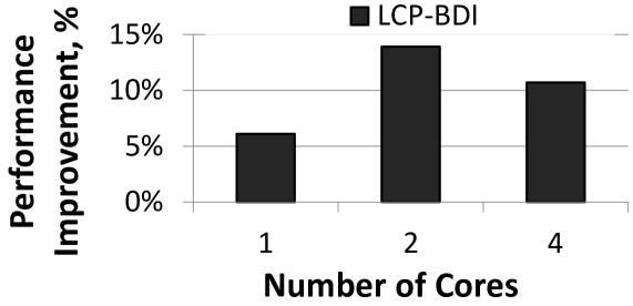
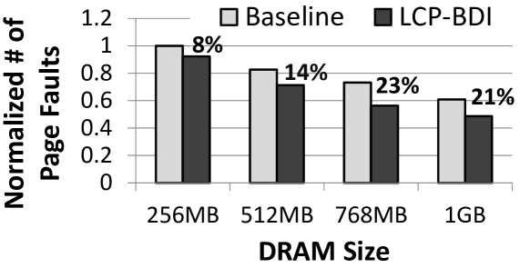
Effect on the Number of Page Faults
Modern systems are usually designed such that concurrently-running applications have enough main memory to avoid most of the potential capacity page faults. At the same time, if the applications’ total working set size exceeds the main memory capacity, the increased number of page faults can significantly affect performance. To study the effect of the LCP-based framework (LCP-BDI) on the number of page faults, we evaluate twenty randomly generated 16-core multiprogrammed mixes of applications from our benchmark set. We also vary the main memory capacity from 256MB to 1GB (larger memories usually lead to almost no page faults for these workload simulations). Our results (Figure 5.13) show that the LCP-based framework (LCP-BDI) can decrease the number of page faults by 21% on average (for 1GB DRAM) when compared with the Baseline design with no compression. We conclude that the LCP-based framework can significantly decrease the number of page faults, and hence improve system performance beyond the benefits it provides due to reduced bandwidth.
5.7.3 Effect on Bus Bandwidth and Memory Subsystem Energy
When DRAM pages are compressed, the traffic between the LLC and DRAM can be reduced. This can have two positive effects: (i) reduction in the average latency of memory accesses, which can lead to improvement in the overall system performance, and (ii) decrease in the bus energy consumption due to the decrease in the number of transfers.
Figure 7.2 shows the reduction in main memory bandwidth between LLC and DRAM (in terms of bytes per kilo-instruction, normalized to the Baseline system with no compression) using different compression designs. The key observation we make from this figure is that there is a strong correlation between bandwidth compression and performance improvement (Figure 7.1). Applications that show a significant reduction in bandwidth consumption (e.g., GemsFDTD, cactusADM, soplex, zeusmp, leslie3d, and the four tpc queries) also see large performance improvements. There are some noticeable exceptions to this observation, e.g., h264ref, wrf and bzip2. Although the memory bus traffic is compressible in these applications, main memory bandwidth is not the bottleneck for their performance.
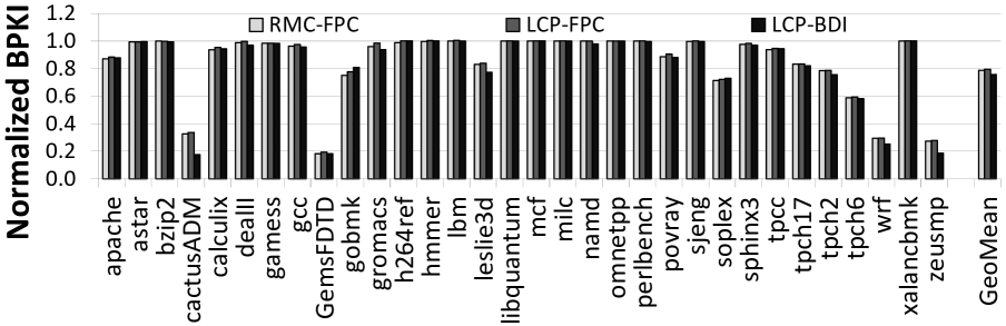
Figure 5.15 shows the reduction in memory subsystem energy of three systems that employ main memory compression—RMC-FPC, LCP-FPC, and LCP-BDI—normalized to the energy of Baseline. The memory subsystem energy includes the static and dynamic energy consumed by caches, TLBs, memory transfers, and DRAM, plus the energy of additional components due to main memory compression: BST [57], MD cache, address calculation, compressor/decompressor units. Two observations are in order.
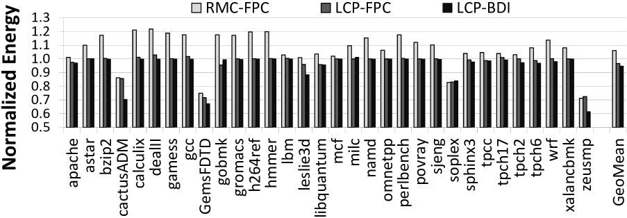
First, our LCP-based designs (LCP-BDI and LCP-FPC) improve the memory subsystem energy by 5.2% / 3.4% on average over the Baseline design with no compression, and by 11.3% / 9.5% over the state-of-the-art design (RMC-FPC) based on [57]. This is especially noticeable for bandwidth-limited applications, e.g., zeusmp and cactusADM. We conclude that our framework for main memory compression enables significant energy savings, mostly due to the decrease in bandwidth consumption.
Second, RMC-FPC consumes significantly more energy than Baseline (6.1% more energy on average, as high as 21.7% for dealII). The primary reason for this energy consumption increase is the physical address calculation that RMC-FPC speculatively performs on every L1 cache miss (to avoid increasing the memory latency due to complex address calculations). The second reason is the frequent (every L1 miss) accesses to the BST table (described in Section 5.2) that holds the address calculation information.
Note that other factors, e.g., compression/decompression energy overheads or different compression ratios, are not the reasons for this energy consumption increase. LCP-FPC uses the same compression algorithm as RMC-FPC (and even has a slightly lower compression ratio), but does not increase energy consumption—in fact, LCP-FPC improves the energy consumption due to its decrease in consumed bandwidth. We conclude that our LCP-based framework is a more energy-efficient main memory compression framework than previously proposed designs such as RMC-FPC.
5.7.4 Analysis of LCP Parameters
Analysis of Page Overflows
As described in Section 5.4.6, page overflows can stall an application for a considerable duration. As we mentioned in that section, we did not encounter any type-2 overflows (the more severe type) in our simulations. Figure 5.16 shows the number of type-1 overflows per instruction. The y-axis uses a log-scale as the number of overflows per instruction is very small. As the figure shows, on average, less than one type-1 overflow occurs every one million instructions. Although such overflows are more frequent for some applications (e.g., soplex and the three tpch queries), our evaluations show that this does not degrade performance in spite of adding a 20,000 cycle penalty for each type-1 page overflow.999We varied the type-1 overflow latency from 10,000 to 100,000 cycles and found that the impact on performance was negligible as we varied the latency. Prior work on main memory compression [57] also used 10,000 to 100,000 cycle range for such overflows. In fact, these applications gain significant performance from our LCP design. The main reason for this is that the performance benefits of bandwidth reduction far outweigh the performance degradation due to type-1 overflows. We conclude that page overflows do not prevent the proposed LCP framework from providing good overall performance.
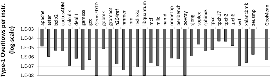
Number of Exceptions
The number of exceptions (uncompressed cache lines) in the LCP framework is critical for two reasons. First, it determines the size of the physical page required to store the LCP. The higher the number of exceptions, the larger the required physical page size. Second, it can affect an application’s performance as exceptions require three main memory accesses on an MD cache miss (Section 5.3.2). We studied the average number of exceptions (across all compressed pages) for each application. Figure 5.17 shows the results of these studies.
The number of exceptions varies from as low as 0.02/page for GemsFDTD to as high as 29.2/page in milc (17.3/page on average). The average number of exceptions has a visible impact on the compression ratio of applications (Figure 5.8). An application with a high compression ratio also has relatively few exceptions per page. Note that we do not restrict the number of exceptions in an LCP. As long as an LCP fits into a physical page not larger than the uncompressed page size (i.e., 4KB in our system), it will be stored in compressed form irrespective of how large the number of exceptions is. This is why applications like milc have a large number of exceptions per page. We note that better performance is potentially achievable by either statically or dynamically limiting the number of exceptions per page—a complete evaluation of the design space is a part of our future work.
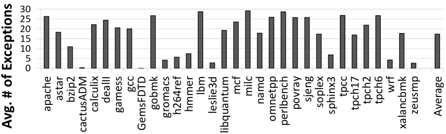
5.7.5 Comparison to Stride Prefetching
Our LCP-based framework improves performance due to its ability to transfer multiple compressed cache lines using a single memory request. Because this benefit resembles that of prefetching cache lines into the LLC, we compare our LCP-based design to a system that employs a stride prefetcher implemented as described in [89]. Figures 5.18 and 5.19 compare the performance and bandwidth consumption of three systems: (i) one that employs stride prefetching, (ii) one that employs LCP-BDI, and (iii) one that employs LCP-BDI along with hints from a prefetcher to avoid cache pollution due to bandwidth compression (Section 5.5.1). Two conclusions are in order.
First, our LCP-based designs (second and third bars) are competitive with the more general stride prefetcher for all but a few applications (e.g., libquantum). The primary reason is that a stride prefetcher can sometimes increase the memory bandwidth consumption of an application due to inaccurate prefetch requests. On the other hand, LCP obtains the benefits of prefetching without increasing (in fact, while significantly reducing) memory bandwidth consumption.
Second, the effect of using prefetcher hints to avoid cache pollution is not significant. The reason for this is that our systems employ a large, highly-associative LLC (2MB 16-way) which is less susceptible to cache pollution. Evicting the LRU lines from such a cache has little effect on performance, but we did observe the benefits of this mechanism on multi-core systems with shared caches (up to 5% performance improvement for some two-core workload mixes—not shown).
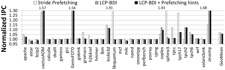
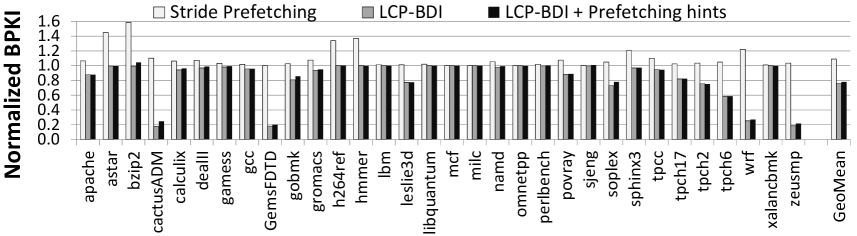
5.8 Summary
Data compression is a promising technique to increase the effective main memory capacity without significantly increasing cost and power consumption. As we described in this chapter, the primary challenge in incorporating compression in main memory is to devise a mechanism that can efficiently compute the main memory address of a cache line without significantly adding complexity, cost, or latency. Prior approaches to addressing this challenge are either relatively costly or energy inefficient.
We proposed a new main memory compression framework, called Linearly Compressed Pages (LCP), to address this problem. The two key ideas of LCP are to use a fixed size for compressed cache lines within a page (which simplifies main memory address computation) and to enable a page to be compressed even if some cache lines within the page are incompressible (which enables high compression ratios). We showed that any compression algorithm can be adapted to fit the requirements of our LCP-based framework.
We evaluated the LCP-based framework using two state-of-the-art compression algorithms (Frequent Pattern Compression and Base-Delta-Immediate Compression) and showed that it can significantly increase effective memory capacity (by 69%) and reduce page fault rate (by 23%). We showed that storing compressed data in main memory can also enable the memory controller to reduce memory bandwidth consumption (by 24%), leading to significant performance and energy improvements on a wide variety of single-core and multi-core systems with different cache sizes. Based on our results, we conclude that the proposed LCP-based framework provides an effective approach for designing low-complexity and low-latency compressed main memory.
Chapter 6 Toggle-Aware Bandwidth Compression
6.1 Introduction
Originally published as “Toggle-Aware Bandwidth Compression for GPUs” in the 22nd International Symposium on High Performance Computer Architecture, 2016 [177], and as “Toggle-Aware Compression for GPUs” in Computer Architecture Letters, 2015 [176].Modern data-intensive computing forces system designers to deliver good system performance under multiple constraints: shrinking power and energy envelopes (power wall), increasing memory latency (memory latency wall), and scarce and expensive bandwidth resources (bandwidth wall). While many different techniques have been proposed to address these issues, these techniques often offer a trade-off that improves one constraint at the cost of another. Ideally, system architects would like to improve one or more of these system parameters, e.g., on-chip and off-chip111Communication channel between the last-level cache and main memory. bandwidth consumption, while simultaneously avoiding negative effects on other key parameters, such as overall system cost, energy, and latency characteristics. One potential way of addressing multiple constraints is to employ dedicated hardware-based data compression mechanisms (e.g., [256, 10, 38, 185, 16]) across different data links in the system. Compression exploits the high data redundancy observed in many modern applications [185, 203, 16, 242] and can be used to improve both capacity (e.g., of caches, DRAM, non-volatile memories [256, 10, 38, 185, 16, 184, 213, 181, 242, 265]) and bandwidth utilization (e.g., of on-chip and off-chip interconnects [46, 12, 230, 204, 184, 213, 242]). Several recent works focus on bandwidth compression to decrease memory traffic by transmitting data in a compressed form in both CPUs [184, 230, 12] and GPUs [204, 184, 242], which results in better system performance and energy consumption. Bandwidth compression proves to be particularly effective in GPUs because they are often bottlenecked by memory bandwidth [166, 104, 105, 262, 242, 175, 81, 106]. GPU applications also exhibit high degrees of data redundancy [204, 184, 242], leading to good compression ratios. While data compression can dramatically reduce the number of bit symbols that must be transmitted across a link, compression also carries two well-known overheads: (1) latency, energy, and area overhead of the compression/decompression hardware [10, 185]; and (2) the complexity and cost to support variable data sizes [73, 203, 184, 213]. Prior work has addressed solutions to both of these problems. For example, Base-Delta-Immediate compression [185] provides a low-latency, low-energy hardware-based compression algorithm. Decoupled and Skewed Compressed Caches [203, 201] provide a mechanism to efficiently manage data recompaction and fragmentation in compressed caches.
6.1.1 Compression & Communication Energy
In this chapter, we make a new observation that there is yet another important problem with data compression that must be addressed to implement energy-efficient communication: transferring data in compressed form (as opposed to uncompressed form) leads to a significant increase in the number of bit toggles, i.e., the number of wires that switch from 0 to 1 or 1 to 0. An increase in bit toggle count causes higher switching activities [236, 25, 29] of wires, leading to higher dynamic energy being consumed by on-chip or off-chip interconnects. The bit toggle count increases for two reasons. First, the compressed data has a higher per-bit entropy because the same amount of information is now stored in fewer bits (the “randomness” of a single bit grows). Second, the variable-size nature of compressed data, which can negatively affect the word/flit data alignment in hardware. Thus, in contrast to the common wisdom that bandwidth compression saves energy (when it is effective), our key observation reveals a new trade-off: energy savings obtained by reducing bandwidth versus energy loss due to higher switching energy during compressed data transfers. This observation and the corresponding trade-off are the key contributions of this work.
To understand (1) how applicable general-purpose data compression is for real GPU applications, and (2) the severity of the problem, we use six compression algorithms to analyze 221 discrete and mobile graphics application traces from a major GPU vendor and 21 open-source, general-purpose GPU applications. Our analysis shows that although off-chip bandwidth compression achieves a significant compression ratio (e.g., more than 47% average effective bandwidth increase with C-Pack [38] across mobile GPU applications), it also greatly increases the bit toggle count (e.g., 2.2 average corresponding increase). This effect can significantly increase the energy dissipated in the on-chip/off-chip interconnects, which constitute a significant portion of the memory subsystem energy.
6.1.2 Toggle-Aware Compression
In this work, we develop two new techniques that make bandwidth compression for on-chip/off-chip buses more energy-efficient by limiting the overall increase in compression-related bit toggles. Energy Control (EC) decides whether to send data in compressed or uncompressed form, based on a model that accounts for the compression ratio, the increase in bit toggles, and current bandwidth utilization. The key insight is that this decision can be made in a fine-grained manner (e.g., for every cache line), using a simple model to approximate the commonly-used and metrics. In this model, is directly proportional to the bit toggle count; is inversely proportional to the compression ratio and directly proportional to the bandwidth utilization. Our second technique, Metadata Consolidation (MC), reduces the negative effects of scattering the metadata across a compressed cache line, which happens with many existing compression algorithms [10, 38]. Instead, MC consolidates compression-related metadata in a contiguous fashion.
Our toggle-aware compression mechanisms are generic and applicable to different compression algorithms (e.g., Frequent Pattern Compression (FPC) [10] and Base-Delta-Immediate (BDI) compression [185]), different communication channels (on-chip/off-chip buses), and different architectures (e.g., GPUs, CPUs, and hardware accelerators). We demonstrate that these mechanisms are mostly orthogonal to different data encoding schemes also used to minimize the bit toggle count (e.g., Data Bus Inversion [221]), and hence can be used together with them to enhance the energy efficiency of interconnects.
Our extensive evaluation shows that our proposed mechanisms can significantly reduce the negative effect of bit toggling increase (in some cases the 2.2 increase in bit toggle count is completely eliminated), while preserving most of the benefits of data compression when it is useful – hence the reduction in performance benefits from compression is usually within 1%. This efficient trade-off leads to the reduction in (i) the DRAM energy that is as high as 28.1% for some applications (8.3% average reduction), and (ii) the total system energy (at most 8.9%, 2.1% on average). Moreover, we can dramatically reduce the energy cost to support data compression over the on-chip interconnect. For example, our toggle-aware compression mechanisms can reduce the original 2.1 increase in consumed energy with C-Pack compression algorithm to much more acceptable 1.1 increase.
6.2 Background
Data compression is a powerful mechanism that exploits the existing redundancy in the applications’ data to relax capacity and bandwidth requirements for many modern systems. Hardware-based data compression was explored in the context of on-chip caches [256, 10, 38, 185, 203, 16] and main memory [3, 230, 57, 184, 213], but mostly for CPU-oriented applications. Several prior works [230, 184, 204, 213, 242, Reetu1] looked at the specifics of memory bandwidth compression, where it is very critical to decide where and when to perform compression and decompression.
While these works looked at energy/power benefits of bandwidth compression, the overhead of compression was limited to the overhead of compression/decompression logic and the overhead of the newly proposed mechanisms/designs. To the best of our knowledge, this is the first work that looks at energy implications of compression on the data transferred over on-chip/off-chip buses. Depending on the type of the communication channel the data bits transferred have different effect on the energy spent on communication. We summarize this effect for three major communication channel types.
On-chip Interconnect. For the full-swing on-chip interconnects, one of the dominant factors that defines the energy cost of a single data transfer (commonly called a flit) is the activity factor—the number of bit toggles on the wires (communication channel switchings from 0 to 1 or from 1 to 0). The bit toggle count for a particular flit depends on both the current flit’s data and on the data that was just sent over the same wires. Several prior works [221, 29, 263, 236, 25] looked at more energy-efficient data communication in the context of on-chip interconnects [29] where the number of bit toggles can be reduced. The key difference between our work and these prior works is that we aim to address the specific effect of increase (sometimes a dramatic increase, see Section 6.3) in bit toggle count due to data compression. Our proposed mechanisms (described in Section 6.4) are mostly orthogonal to these prior mechanisms and can be used in parallel with them to achieve even larger energy savings in data transfers.
DRAM bus. In the case of DRAM (e.g., GDDR5 [98]), the energy attributed to the actual data transfer is usually less than the background and activate energy, but still significant (16% on average based on our estimation with the Micron power calculator [158]). The second major distinction between on-chip and off-chip buses, is the definition of bit toggles. In case of DRAM, bit toggles are defined as the number of zero bits. Reducing the number of signal lines driving a low level (zero bit) results in reduced power dissipation in the termination resistors and output drivers [98]. To reduce the number of zero bits, techniques like DBI (data-bus-inversion) are usually used. For example, DBI is the part of the standard for GDDR5 [98] and DDR4 [97]. As we will show later in Section 6.3, these techniques are not effective enough to handle the significant increase in bit toggles due to data compression.
PCIe and SATA. For SATA and PCIe, data is transmitted in a serial fashion at much higher frequencies than typical parallel bus interfaces. Under these conditions, bit toggles impose different design considerations and implications. Data is transmitted across these buses without an accompanying clock signal which means that the transmitted bits need to be synchronized with a clock signal by the receiver. This clock recovery requires frequent bit toggles to prevent loss in information. In addition, it is desirable that the running disparity—which is the difference in the number of one and zero bits transmitted—be minimized. This condition is referred to as DC balance and prevents distortion in the signal. Data is typically scrambled using encodings like the 8b/10b encoding [245] to balance the number of ones and zeros while ensuring frequent transitions. These encodings have high overhead in terms of the amount of additional data transmitted but obscure any difference in bit transitions with compressed or uncompressed data. As the result, we do not expect further compression or toggle-rate reduction techniques to apply well to interfaces like SATA and PCIe.
Summary. With on-chip interconnect, any bit transitions increase the energy expended during data transfers. In the case of DRAM, energy spent during data transfers increases with an increase in zero bits. Data compression exacerbates the energy expenditure in both these channels. For PCIe and SATA, data is scrambled before transmission and this obscures any impact of data compression and hence, our proposed mechanisms are not applicable to these channels.
6.3 Motivation and Analysis
In this work, we examine the use of six compression algorithms for bandwidth compression in GPU applications, taking into account bit toggles: (i) FPC (Frequent Pattern Compression) [10]; (ii) BDI (Base-Delta-Immediate Compression) [185]; (iii) BDI+FPC (combined FPC and BDI) [184]; (iv) LZSS (Lempel-Ziv compression) [268, 3]; (v) Fibonacci (a graphics-specific compression algorithm) [187]; and (vi) C-Pack [38]. All of these compression algorithms explore different forms of redundancy in memory data. For example, FPC and C-Pack algorithms look for different static patterns in data (e.g., high order bits are zeros or the word consists of repeated bytes). At the same time, C-Pack allows partial matching with some locally defined dictionary entries that usually gives it better coverage than FPC. In contrast, the BDI algorithm is based on the observation that the whole cache line of data can be commonly represented as a set of one or two bases and the deltas from these bases. This allows compression of some cache lines much more efficiently than FPC and even C-Pack, but potentially leads to lower coverage. For completeness of our compression algorithms analysis, we also examine the well-known software-based mechanism called LZSS, and the recently proposed graphics-oriented Fibonacci algorithm.
To ensure our conclusions are practically applicable, we analyze both the real GPU applications (both discrete and mobile ones) with actual data sets provided by a major GPU vendor and open-sourced GPU computing applications [170, 36, 79, 31]. The primary difference is that discrete applications have more single and double precision floating point data, mobile applications have more integers, and open-source applications are in between. Figure 6.1 shows the potential of these six compression algorithms in terms of effective bandwidth increase, averaged across all applications. These results exclude simple data patterns (e.g., zero cache lines) that are already handled by modern GPUs efficiently, and assume practical boundaries on bandwidth compression ratios (e.g., for on-chip interconnect, the highest possible compression ratio is 4.0, because the minimum flit size is 32 bytes while the uncompressed packet size is 128 bytes).
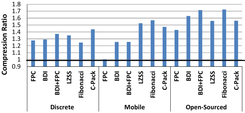
First, for the 167 discrete GPU applications (left side of Figure 6.1), all algorithms provide substantial increase in available bandwidth (25%–44% on average for different compression algorithms). It is especially interesting that simple compression algorithms are very competitive with the more complex GPU-oriented Fibonacci algorithm and the software-based Lempel-Ziv algorithm [268]. Second, for the 54 mobile GPU applications (middle part of Figure 6.1), bandwidth benefits are even more pronounced (reaching up to 57% on average with the Fibonacci algorithm). Third, for the 21 open-sourced GPU computing applications the bandwidth benefits are the highest (as high as 72% on average with the Fibonacci and BDI+FPC algorithms). Overall, we conclude that existing compression algorithms (including simple, general-purpose ones) can be effective in providing high on-chip/off-chip bandwidth compression for GPU compute applications.
Unfortunately, the benefits of compression come with additional costs. Two overheads of compression are well-known: (i) additional data processing due to compression/decompression, and (ii) hardware changes due to transfer variable-length cache lines. While these two problems are significant, multiple compression algorithms [10, 256, 185, 54] have been proposed to minimize the overheads of data compression/decompression. Several designs [213, 204, 184, 242] integrate bandwidth compression into existing memory hierarchies. In this work, we identify a new challenge with data compression that needs to be addressed: the increase in the total number of bit toggles as a result of compression.
On-chip data communication energy is directly proportional to the number of bit toggles on the communication channel [236, 25, 29], due to the charging and discharging of the channel wire capacitance with each toggle. Data compression may increase or decrease the bit toggle count on the communication channel for any given data. As a result, energy consumed for moving this data can change. Figure 6.2 shows the increase in bit toggle count for all GPU applications in our workload pool with the six compression algorithms over a baseline that employs zero line compression (as this is already efficiently done in modern GPUs). The total number of bit toggles is computed such that it already includes the positive effects of compression (i.e., the decrease in the total number of bits sent due to compression).
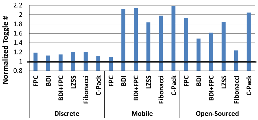
We make two observations. First, all compression algorithms consistently increase the bit toggle count. The effect is significant yet smaller (12%–20% increase) in discrete applications, mostly because they include floating-point data, which already has high toggle rates (31% on average across discrete applications) and is less amenable to compression. This increase in bit toggle count happens even though we transfer less data due to compression. If this effect would be only due to the higher density of information per bit, we would expect the increase in the bit toggle rate (the relative percentage of bit toggles per data transfer), but not in the bit toggle count (the total number of bit toggles).
Second, the increase in bit toggle count is more dramatic for mobile and open-sourced applications (right two-thirds of Figure 6.2), exceeding 2 in four cases.222The FPC algorithm is not as effective in compressing mobile application data in our pool, and hence does not greatly affect bit toggle count. For all types of applications, the increase in bit toggle count can lead to significant increase in the dynamic energy consumption of the communication channels.
We study the relationship between the achieved compression ratio and the resultant increase in bit toggle count. Figure 6.3 shows the compression ratio and the normalized bit toggle count of each discrete GPU application after compression with the FPC algorithm.333We observe similarly-shaped curves for other compression algorithms. Clearly, there is a positive correlation between the compression ratio and the increase in bit toggle count, although it is not a simple direct correlation—higher compression ratio does not necessarily means higher increase in bit toggle count. To make things worse, the behaviour might change within an application due to phase and data patterns changes.
We draw two major conclusions from this study. First, it strongly suggests that successful compression may lead to increased dynamic energy dissipation by on-chip/off-chip communication channels due to increased toggle counts. Second, these results show that any efficient solution for this problem should probably be dynamic in its nature to adopt for data pattern changes during applications execution.
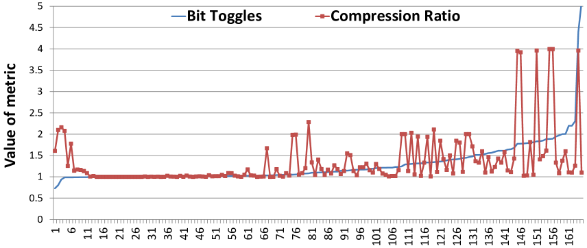
To understand the toggle increase phenomenon, we examined several example cache lines where bit toggle count increases significantly after compression. Figures 6.4 and 6.5 show one of these cache lines with and without compression (FPC), assuming 8-byte flits.
Without compression, the example cache line in Figure 6.4, which consists of 8-byte data elements (4-byte indices and 4-byte pointers) has a very low number of toggles (2 toggles per 8-byte flit). This low number of bit toggles is due to the favourable alignment of the uncompressed data with the boundaries of flits (i.e., transfer granularity in the on-chip interconnect). With compression, the toggle count of the same cache line increases significantly, as shown in Figure 6.5 (e.g., 31 toggles for a pair of 8-byte flits in this example). This increase is due to two major reasons. First, because compression removes zero bits from narrow values, the resulting higher per-bit entropy leads to higher “randomness” in data and, thus, a larger toggle count. Second, compression negatively affects the alignment of data both at the byte granularity (narrow values replaced with shorter 2-byte versions) and bit granularity (due to the 3-bit metadata storage; e.g., is the encoding metadata used to indicate narrow values for the FPC algorithm).
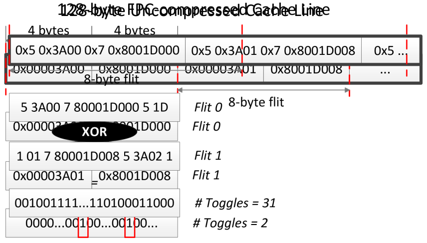
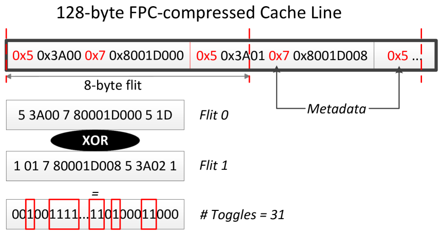
6.4 Toggle-aware Compression
6.4.1 Energy vs. Performance Trade-off
Data compression can reduce energy consumption and improve performance by reducing communication bandwidth demands. At the same time, data compression can potentially lead to significantly higher energy consumption due to increased bit toggle count. To properly evaluate this trade-off, we examine commonly-used metrics like and [70]. We estimate these metrics with a simple model, which helps to make compression-related performance/energy trade-offs. We define the of a single data transfer to be proportional to the bit toggle count associated with it. Similarly, is defined to be inversely proportional to performance, which we assume is proportional to bandwidth reduction (i.e., compression ratio) and bandwidth utilization. The intuition behind this heuristic is that compression ratio reflects on how much additional bandwidth we can get, while bandwidth utilization shows how useful this additional bandwidth is in improving performance. Based on the observations above, we develop two techniques to enable toggle-aware compression to reduce the negative effects of increased bit toggle count.
6.4.2 Energy Control (EC)
We propose a generic Energy Control (EC) mechanism that can be applied along with any current (or future) compression algorithm.444In this work, we assume that only memory bandwidth is compressed, while on-chip caches and main memory still store data in uncompressed form. It aims to achieve high compression ratio while minimizing the bit toggle count. As shown in Figure 6.6, the Energy Control mechanism uses a generic decision function that considers (i) the bit toggle count for transmitting the original data (), (ii) the bit toggle count for transmitting the data in compressed form (), (iii) compression ratio (), (iv) current bandwidth utilization (), and possibly other metrics of interest that can be gathered and analyzed dynamically to decide whether to transmit the data compressed or uncompressed. Using this approach, it is possible to achieve a desirable trade-off between overall bandwidth reduction and increase/decrease in communication energy. The decision function that compares the compression ratio () and toggle ratio () can be linear (, based on ) or quadratic (, based on ).555We also find a specific coefficient in the relative weight between and empirically. Specifically, when the bandwidth utilization () is very high (e.g., ), we incorporate it into our decision function by multiplying the compression ratio with , hence allocating more weight to the compression ratio. Since the data patterns during application execution could change drastically, we expect our mechanism to be applied dynamically (either per cache line or a per region of execution) rather than statically for the whole application execution.
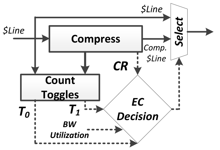
6.4.3 Metadata Consolidation
Traditional energy-oblivious compression algorithms are not optimized to minimize the bit toggle count. Most of these algorithms [38, 10, 187] have distributed metadata to efficiently track the redundancy in data, e.g., several bits per word to represent the current pattern used for encoding. These metadata bits can significantly increase the bit toggle count as they shift the potentially good alignment between different words within a cache line (Section 6.3). It is possible to enhance these compression algorithms (e.g., FPC and C-Pack) such that the increase in bit toggle count would be less after compression is applied. Metadata Consolidation (MC) is a new technique that aims to achieve this. The key idea of MC is to consolidate compression-related metadata into a single contiguous metadata block instead of storing (or, scattering) such metadata in a fine-grained fashion, e.g., on a per-word basis. We can locate this single metadata block either before or after the actual compressed data (this can increase decompression latency since the decompressor needs to know the metadata). The major benefit of MC is that it eliminates misalignment at the bit granularity. In cases where a cache line has a majority of similar patterns, a significant portion of the toggle count increase can be avoided.
Figure 6.7 shows an example cache line compressed with the FPC algorithm, with and without MC. We assume 4-byte flits. Without MC, the bit toggle count between the first two flits is 18 (due to per-word metadata insertion). With MC, the corresponding bit toggle count is only 2, showing the effectiveness of MC in reducing bit toggles.
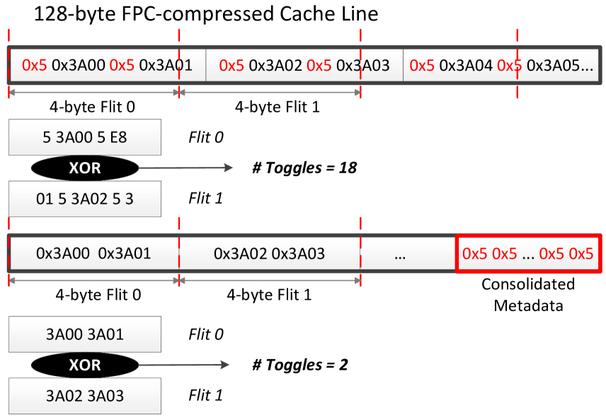
6.5 EC Architecture
In this work, we assume a system where global on-chip network and main memory communication channels are augmented with compressor and decompressor units as described in Figure 6.8 and Figure 6.9. While it is possible to store data in the compressed form as well (e.g., to improve the capacity of on-chip caches [256, 10, 185, 38, 203, 16]), the corresponding changes come with potentially significant hardware complexity that we would like to avoid in our design. We first attempt to compress the data traffic coming in and out of the channel with one (or a few) compression algorithms. The results of the compression, both the compressed cache line size and data, are then forwarded to the Energy Control (EC) logic that is described in detail in Section 6.4. EC decides whether it is beneficial to send data in the compressed or uncompressed form, after which the data is transferred over the communication channel. It is then decompressed if needed at the other end, and the data flow proceeds normally. In the case of main memory bus compression (Figure 6.9), additional EC and compressor/decompressor logic can be implemented in the already existing base-layer die assuming stacked memory organization [100, 85], or in the additional layer between DRAM and the main memory bus. Alternatively, the data can be stored in the compressed form but without any capacity benefits [204, 213].
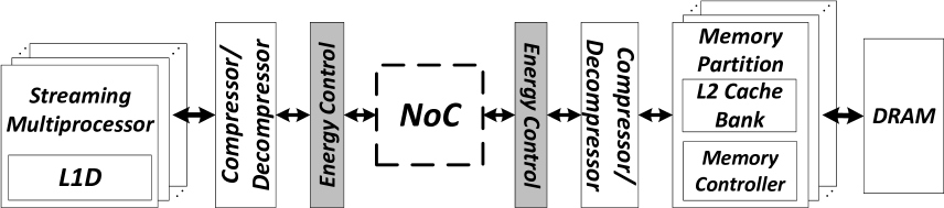
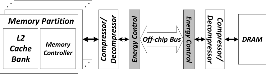
6.5.1 Toggle Computation for On-Chip Interconnect
As described in Section 6.4, our proposed mechanism, EC, aims to decrease the negative effect of data compression on bit toggling while preserving most of the compression benefits. GPU on-chip communication is performed via exchanging packets at a cache line size granularity. But the physical width of the on-chip interconnect channels is usually several times smaller than the size of a cache line (e.g., 32-byte wide channels for 128-byte cache lines). As a result, the communication packet is divided into multiple flits that are stored at the transmission queue buffer before being transmitted over the communication channel in a sequential manner. Our approach adds a simple bit toggle computation logic that computes the bit toggle count across flits awaiting transmission. This logic consists of a flit-wide array of XORs and a tree-adder to compute the hamming distance, the number of bits that are different, between two flits. We perform this computation for both compressed and uncompressed data, and the results are then fed to the EC decision function (as described in Figure 6.6). This computation can be done sequentially while reusing the transition queue buffers to store intermediate compressed or uncompressed flits, or in parallel with the addition of some dedicated flit buffers (to reduce the latency overhead). In this work we assume the second approach.
6.5.2 Toggle Computation for DRAM
For modern DRAMs [98, 97] the bit toggle definition is different from the definition we used for on-chip interconnects. As we described in Section 6.2, in the context of main memory bus what matters is the number of zero bits per data transfer. This defines how we compute the toggle count for DRAM transfers by simply counting the zero bits—which is known as the hamming weight or the population count of the inverted value. The difference in defining the toggle count also leads to the fact that the current toggle count does not depend on the previous data, which means that no additional buffering is required to perform the computation.
6.5.3 EC and Data Bus Inversion
Modern communication channels use different techniques to minimize (and sometimes to maximize) the bit toggle count to reduce the energy consumption or/and preserve signal integrity. We now briefly summarize two major techniques used in existing on-chip/off-chip interconnects: Data Bus Inversion and Data Scrambling, and their effect on our proposed EC mechanism.
Data Bus Inversion
Data Bus Inversion is an encoding technique proposed to reduce the power consumption in data channels. Two commonly used DBI algorithms include Bus invert coding [221] and Limited-weight coding [219, 220]. Bus invert coding places an upper-bound on the number of bit flips while transmitting data along a channel. Consider a set of N bit lines transmitting data in parallel. If the Hamming distance between the previous and current data value being transmitted exceeds N/2, the data is transmitted in the inverted form. This limits the number of bit flips to N/2. To preserve correctness, an additional bit line carries the inverted status of each data tranmission. By reducing the number of bit flips, Bus invert coding reduces the switching power associated with charging and discharging of bit lines.
Limited weight coding is a DBI technique that helps reduce power when one of the two different bus states is more dissipative than the other. The algorithm only observes the current state of data. It decides to invert or leave the data inverted based on the goal of minimizing either the number of zeros or ones being transmitted.
Implementing Bus invert coding requires much the same circuitry for toggle count determination in the proposed EC mechanism. Here, hardware logic is required to compute the XOR between the different prior and current data at a fixed granularity. The Hamming distance is then computed by summing the number of 1’s using a simple adder. Similar logic is required to compute the toggle count for compressed versus uncompressed data in the Energy Control mechanism. We expect that both EC and DBI can efficiently coexist. After compression is applied, we first apply DBI (to minimize the bit toggles), and after that we apply EC mechanism to evaluate the tradeoff between the compression ratio and the bit toggle count.
Data Scrambling
To minimize the signal distortion, some modern DRAM designs [102, 161] use a data scrambling technique that aims to minimize the running data disparity, i.e., the difference between the number of 0s and 1s, in the transmitted data. One way to “randomize” the bits is by XORing them with a pseudo-random values generated at boot time [161]. While techniques like data scrambling can potentially decrease signal distortion, they also increase the dynamic energy of DRAM data transfers. This approach also contradicts what several designs aimed to achieve by using DBI for GDDR5 [98] and DDR4 [97], since the bits become much more random. In addition, using pseudo-random data scrambling techniques can be motivated by the existence of certain pathological data patterns [161], where signal integrity requires much lower operational frequency. At the same time, those patterns can usually be handled well with data compression algorithms that can provide the appropriate data transformation to avoid repetitive failures at a certain frequency. For the rest of this chapter, we assume GDDR5 memory without scrambling.
6.5.4 Complexity Estimation
Toggle count computation is the main hardware addition introduced by the EC mechanism. We modeled and synthesized the toggle-computational block in Verilog. Our results show that the required logic can be performed in an energy-efficient way (4pJ per 128-byte cache line with 32-byte flits for 65nm process666This is significantly lower than the corresponding energy for compression and decompression [213].).
6.6 Methodology
In our work, we analyze two distinct groups of applications. First, a group of 221 applications from a major GPU vendor in the form of memory traces with real application data. This group consists of two subgroups: discrete applications (e.g., HPC workloads, general-purpose applications, physics etc.) and mobile applications. As there is no existing simulator that can run these traces for cycle-accurate simulation, we use them to demonstrate (i) the benefits of compression on a large pool of existing applications operating on real data, and (ii) the existence of the toggle count increase problem. Second, we use 21 open-sourced GPU computing applications derived from CUDA SDK [170] (BFS, CONS, JPEG, LPS, MUM, RAY, SLA, TRA), Rodinia [36] (hs, nw), Mars [79] (KM, MM, PVC, PVR, SS), and Lonestar [31] (bfs, bh, mst, sp, sssp) suites.
We evaluate the performance of our proposed mechanisms with the second group of applications using GPGPU-Sim 3.2.2 [22] cycle-accurate simulator. Table 6.1 provides all the details of the simulated system. Additionally, we use GPUWattch [141] for energy analysis with proper modifications to reflect bit-toggling effect. We run all applications to completion or 1 billion instructions (whichever comes first). Our evaluation in Section 6.7 demonstrates detailed results for applications that exhibit at least 10% bandwidth compressibility.
Evaluated Metrics. We present Instruction per Cycle (IPC) as the primary performance metric. In addition, we also use average bandwidth utilization defined as the fraction of total DRAM cycles that the DRAM data bus is busy, and compression ratio defined as the effective bandwidth increase. For both on-chip interconnect and DRAM we assume the highest possible compression ratio of 4.0. For on-chip interconnect, this is because we assume a flit size of 32 bytes for a 128-byte packet. For DRAM, there are multiple ways of achieving the desired flexibility in data transfers: (i) increasing the size of a cache line (from 128 bytes to 256 bytes), (ii) using sub-ranking as was proposed for DDR3 in MemZip [213], (iii) transferring multiple compressed cache lines instead of one uncompressed line as in LCP design [184], and (iv) any combination of the first three approaches. Existing GPUs (e.g., GeForce FX series) are known to support 4:1 data compression [1].
| System Overview | 15 SMs, 32 threads/warp, 6 memory channels |
|---|---|
| Shader Core Config | 1.4GHz, GTO scheduler [198], 2 schedulers/SM |
| Resources / SM | 48 warps/SM, 32K registers, 32KB Shared Mem. |
| L1 Cache | 16KB, 4-way associative, LRU |
| L2 Cache | 768KB, 16-way associative, LRU |
| Interconnect | 1 crossbar/direction (15 SMs, 6 MCs), 1.4GHz |
| Memory Model | 177.4GB/s BW, 6 GDDR5 Memory Controllers, |
| FR-FCFS scheduling, 16 banks/MC | |
| GDDR5 Timing [98] | |
6.7 Evaluation
We present our results for two communication channels described above: (i) off-chip DRAM bus and (ii) on-chip interconnect. We exclude LZSS compression algorithm from our detailed evaluation since its hardware implementation is not practical with hundreds of cycles of compression/decompression latency [3].
6.7.1 DRAM Bus Results
Effect on Toggles and Compression Ratio
We analyze the effectiveness of the proposed EC optimization by examining how it affects both the number of toggles (Figure 6.10) and the compression ratio (Figure 6.11) for five compression algorithms. In both figures, results are averaged across all applications within the corresponding application subgroup and normalized to the baseline design with no compression. Unless specified otherwise, we use the EC mechanism with the decision function based on the metric using our model from Section 6.4.2. We make two observations from these figures.
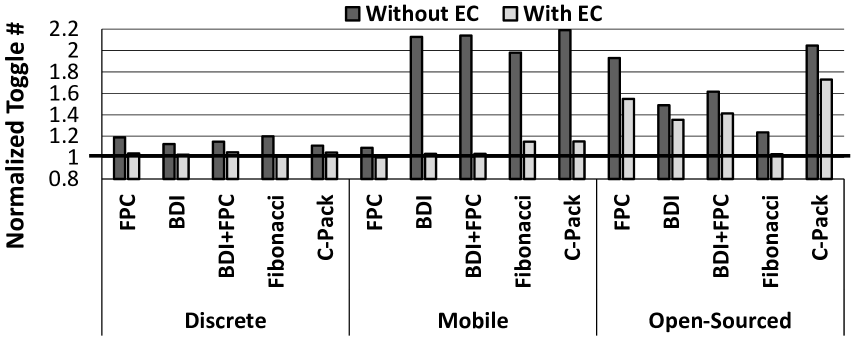
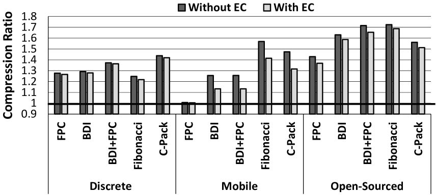
First, we observe that EC can effectively reduce the overhead in terms of toggle count for both discrete and mobile GPU applications (Figure 6.10). For discrete GPU applications, the toggle reduction varies from 6% to 16% on average, and the toggle increase due to compression is almost completely eliminated in the case of the Fibonacci compression algorithm. For mobile GPU applications, the reduction is as high as 51% on average for the BDI+FPC compression algorithm (more than 32 reduction in extra bit toggles), with only a modest reduction777Compression ratio reduces because EC decides to transfer some compressible lines in the uncompressed form. in compression ratio.
Second, the reduction in compression ratio with EC is usually minimal. For example, in discrete GPU applications, this reduction for the BDI+FPC algorithm is only 0.7% on average (Figure 6.11). For mobile and open-sourced GPU applications, the reduction in compression ratio is more noticeable (e.g., 9.8% on average for Fibonacci with mobile applications), which is still a very attractive trade-off since the 2.2 growth in the number of toggles is practically eliminated. We conclude that EC offers an effective way to control the energy efficiency of data compression for DRAM by applying it only when it provides a high compression ratio with only a small increase in the number of toggles.
While the average numbers presented express the general effect of the EC mechanism on both the number of toggles and compression ratio, it is also interesting to see how the results vary for individual applications. To perform this deeper analysis, we pick one compression algorithm (C-Pack), and a single subgroup of applications (Open-Sourced), and show the effect of compression with and without EC on the toggle count (Figure 6.12) and compression ratio (Figure 6.13). We also study two versions of the EC mechanism: (i) EC1 which uses the metric and (ii) EC2 which uses the metric. We make three major observations from these figures.
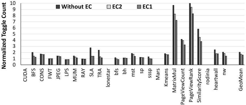
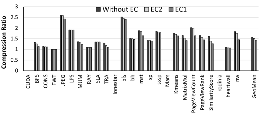
First, both the increase in bit toggle count and compression ratio vary significantly for different applications. For example, bfs from the Lonestar application suite has a very high compression ratio of more than 2.5, but its increase in toggle count is relatively small (only 17% for baseline C-Pack compression without EC mechanism). In contrast, PageViewRank application from the Mars application suite has more than 10 increase in toggles with 1.6 compression ratio. This is because different data is affected differently by data compression. There can be cases where the overall toggle count is lower than in the uncompressed baseline even without EC mechanism (e.g., LPS).
Second, for most of the applications in our workload pool, the proposed mechanisms (EC1 and EC2) can significantly reduce the bit toggle count while retaining most of the benefits of compression. For example, for heartwall we reduce the bit toggle count with our EC2 mechanism from 2.5 to 1.8 by only sacrificing 8% of the compression ratio (from 1.83 to 1.75). This could significantly reduce the bit toggling energy overhead with C-Pack algorithm while preserving most of the bandwidth (and hence potentially performance) benefits.
Third, as expected, EC1 is more aggressive in disabling compression, because it weights bit toggles and compression ratio equally in the trade-off, while in the EC2 mechanism, compression ratio has higher value (squared in the formula) than bit toggle count. Hence, for many of our applications (e.g., bfs, mst, Kmeans, nw, etc.) we see a gradual reduction in toggles, with corresponding small reduction in compression ratio, when moving from baseline to EC1 and then EC2. This means that depending on the application characteristics, we have multiple options with varying aggressiveness to trade-off bit toggle count with compression ratio. As we will show in the next section, we can achieve these trade-offs with minimal effect on performance.
Effect on Performance
While previous results show that EC1 and EC2 mechanisms are very effective in trading off bit toggle count with compression ratio, it is still important to understand how much this trade-off “costs” in actual performance. This is especially important for the DRAM, that is commonly one of the major bottlenecks in GPU applications performance, and hence even a minor degradation in compression ratio can potentially lead to a noticeable degradation in performance and overall energy consumption. Figure 6.14 shows this effect on performance for both EC1 and EC2 mechanisms in comparison to a baseline employing compression with C-Pack. We make two observations here.
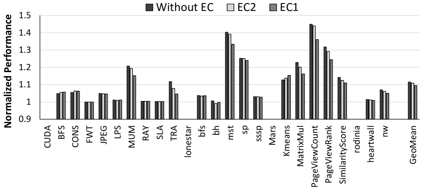
First, our proposed mechanisms (EC1 and EC2) usually have minimal negative impact on the applications’ performance. The baseline mechanism (Without EC) provides 11.5% average performance improvement, while the least aggressive EC2 mechanism reduces performance benefits by only 0.7%, and the EC1 mechanism - by 2.0%. This is significantly smaller than the corresponding loss in compression ratio (shown in Figure 6.13). The primary reason is a successful trade-off between compression ratio, toggles and performance. Both EC mechanisms consider current DRAM bandwidth utilization, and only trade-off compression when it is unlikely to hurt performance.
Second, while there are applications (e.g., MatrixMul) where we could lose up to 6% performance using the most aggressive mechanism (EC1), this is absolutely justified because we also reduce the bit toggle count from almost 10 to about 7. It is hard to avoid any degradation in performance for such applications since they are severely bandwidth-limited, and any loss in compression ratio is conspicuous in performance. If such performance degradation is unacceptable, then a less aggressive version of the EC mechanism, EC2, can be used. Overall, we conclude that our proposed mechanisms EC1 and EC2 are both very effective in preserving most of the performance benefit that comes from data compression while significantly reducing the negative effect of bit toggling increase (and hence reducing the energy overhead).
Effect on DRAM and System Energy
Figure 6.15 shows the effect of C-Pack compression algorithm on the DRAM energy consumption with and without energy control (normalized to the energy consumption of the uncompressed baseline). These results include the overhead of the compression/decompression hardware [38] and our mechanism (Section 6.5.4). and We make two observations from the figure. First, as expected, many applications significantly reduce their DRAM energy consumption (e.g., SLA, TRA, heartwall, nw). For example, for TRA, the 28.1% reduction in the DRAM energy (8.9% reduction in the total energy) is the direct cause of the significant reduction in the bit toggle count (from 2.4 to 1.1 as shown in Figure 6.12). Overall, the DRAM energy is reduced by 8.3% for both EC1 and EC2. As DRAM energy constitutes on average 28.8% out of total system energy (ranging from 7.9% to 58.3%), and the decrease in performance is less than 1%, this leads to a total system energy reduction of 2.1% on average across applications using EC1/EC2 mechanisms.
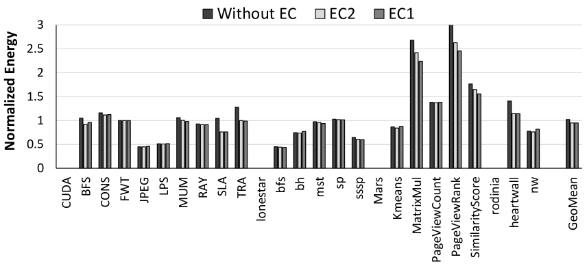
Second, many applications that have significant growth in their bit toggle count due to compression (e.g., MatrixMul and PageViewRank) are also very sensitive to the available DRAM bandwidth. Therefore to provide any energy savings for these applications, it is very important to dynamically monitor their current bandwidth utilization. We observe that without the integration of current bandwidth utilization metric into our mechanisms (described in Section 6.4.2), even a minor reduction in compression ratio for these applications could lead to a severe degradation in performance, and system energy. We conclude that our proposed mechanisms can efficiently trade off compression ratio and bit toggle count to improve both the DRAM and overall system energy.
6.7.2 On-Chip Interconnect Results
Effect on Toggles and Compression Ratio
Similar to the off-chip bus, we evaluate the effect of five compression algorithms on toggle count and compression ratio for the on-chip interconnect (Figure 6.16 and Figure 6.17 correspondingly) using GPGPU-sim and open-sourced applications as described in Section 6.6. We make three major observations from these figures.
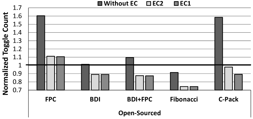
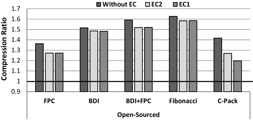
First, the most noticeable difference when compared with the DRAM bus is that the increase in bit toggle count is not as significant for all compression algorithms. It still increases for all but one algorithm (Fibonacci), but we observe steep increases in bit toggle count (e.g., around 60%) only for FPC and C-Pack algorithms. The reason for this behaviour is two fold. First, the on-chip data working set is different from that of the off-chip working set for some applications, and hence these data sets have different characteristics. Second, we define bit toggles differently for these two channels (see Section 6.2).
Second, despite the variation in how different compression algorithms affect the bit toggle count, both of our proposed mechanisms are effective in reducing the bit toggle count (e.g., from 1.6 to 0.9 with C-Pack). Moreover, both mechanisms, EC1 and EC2, preserve most of the compression ratio achieved by C-Pack algorithm. Therefore, we conclude that our proposed mechanisms are effective in reducing bit toggles for both on-chip interconnect and off-chip buses.
Third, in contrast to our evaluation of the DRAM bus, our results with interconnect show that for all but one algorithm (C-Pack), both EC1 and EC2 are almost equally effective in reducing the bit toggle count while preserving the compression ratio. This means that in the case of on-chip interconnect, there is no need to use more aggressive decision functions to trade-off bit toggles with compression ratio, because the EC2 mechanism—the less aggressive of the two—already provides most of the benefits.
Finally, while the overall achieved compression ratio is slightly lower than in case of DRAM, we still observe impressive compression ratios in on-chip interconnect, reaching up to 1.6 on average across all open-sourced applications. While DRAM bandwidth traditionally is a primary performance bottleneck for many applications, on-chip interconnect is usually designed such that its bandwidth will not be the primary performance limiter. Therefore the achieved compression ratio in case of on-chip interconnect is expected to translate directly into overall area and silicon cost reduction assuming fewer ports, wires and switches are required to provide the same effective bandwidth. Alternatively, the compression ratio can be translated into lower power and energy assuming lower clock frequency can be applied due to lower bandwidth demands from on-chip interconnect.
Effect on Performance and Interconnect Energy
While it is clear that both EC1 and EC2 are effective in reducing the bit toggle count, it is important to understand how they affect performance and interconnect energy in our simulated system. Figure 6.18 shows the effect of both proposed techniques on performance (normalized to the performance of the uncompressed baseline). The key takeaway from this figure is that for all compression algorithms, both EC1 and EC2 are within less than 1% of the performance of the designs without the energy control mechanisms. There are two reasons for this. First, both EC1 and EC2 are effective in deciding when compression is useful to improve performance and when it is not. Second, the on-chip interconnect is less of a bottleneck in our example configuration than the off-chip bus, hence disabling compression in some cases has smaller impact on the overall performance.
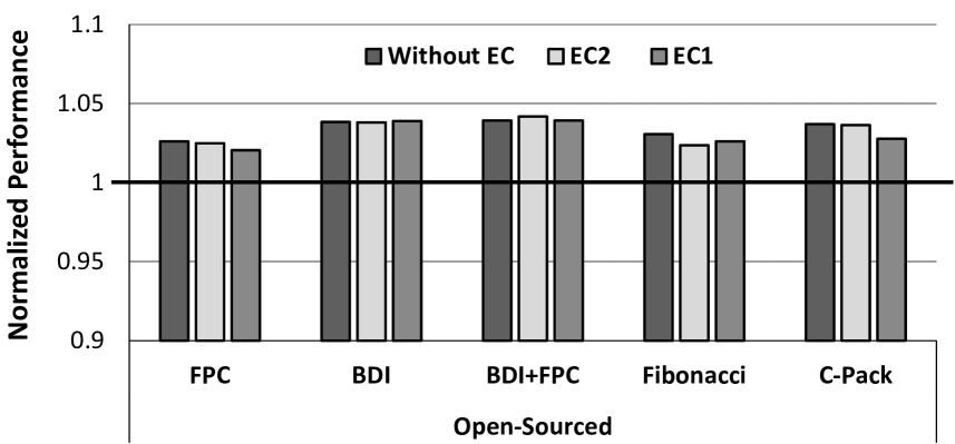
Figure 6.19 shows the effect of data compression and bit toggling on the energy consumed by the on-chip interconnect (results are normalized to the energy of the uncompressed interconnect). As expected, compression algorithms that have higher bit toggle count, have much higher energy cost to support data compression, because bit toggling is the dominant part of the on-chip interconnect energy consumption. From this figure, we observe that our proposed mechanisms, EC1 and EC2, are both effective in reducing the energy overhead. The most notable reduction is for C-Pack algorithm, where we reduce the overhead from 2.1 to just 1.1.
Overall, we conclude that our mechanisms are effective in reducing the energy overheads related to increased bit toggling due to compression, while preserving most of the bandwidth and performance benefits achieved through compression.
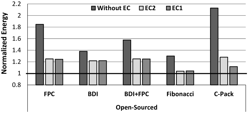
6.7.3 Effect of Metadata Consolidation
Metadata Consolidation (MC) is able to reduce the bit-level misalignment for several compression algorithms (currently implemented for FPC and C-Pack compression algorithms). We observe additional toggle reduction on the DRAM bus from applying MC (over EC2) of 3.2% and 2.9% for FPC and C-Pack respectively across applications in the discrete and mobile subgroups. Even though MC can mitigate some negative effects of bit-level misalignment after compression, it is not effective in cases where data values within the cache line are compressed to different sizes. These variable sizes frequently lead to misalignment at the byte granularity. While it is possible to insert some amount of padding into the compressed line to reduce the misalignment, this would counteract the primary goal of compression to minimize data size.
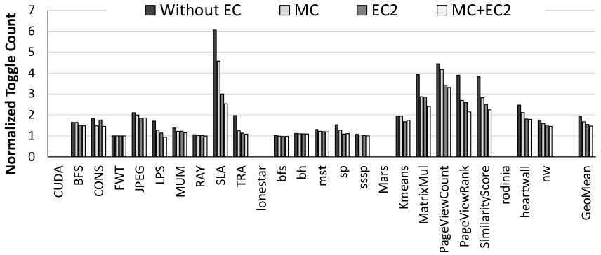
We also conducted an experiment with open-sourced applications where we compare the impact of MC and EC separately, as well as together, for the FPC compression algorithm. We observe similar results with the C-Pack compression algorithm. Figure 6.20 lead to two observations. First, when EC is not employed, MC can substantially reduce the bit toggle count, from 1.93 to 1.66 on average. Hence, in the case when the hardware changes related to EC implementation are undesirable, MC can be used to avoid some of the increase in the bit toggle count. Second, when energy control is employed (see EC2 and MC+EC2), the additional reduction in bit toggle count is relatively small. This means that EC2 mechanism can cover most of the benefits that MC can provide. In summary, we conclude that MC mechanism can be effective in reducing the bit toggle count when energy control is not used. It does not require significant hardware changes other than the minor modifications in the compression algorithm itself. At the same time, in the presence of energy control mechanism, the additional effect of MC in toggle reduction is marginal.
6.8 Related Work
To the best of our knowledge, this is the first work that (i) identifies increased bit toggle count in communication channels as a major drawback in enabling efficient data compression in modern systems, (ii) evaluates the impact and causes for this inefficiency in modern GPU architectures for different channels across multiple compression algorithms, and (iii) proposes and extensively evaluates different mechanisms to mitigate this effect to improve overall energy efficiency. We first discuss prior works that propose more energy efficient designs for DRAM, interconnects and mechanisms for energy efficient data communication in on-chip/off-chip buses and other communication channels. We then discuss prior work that aims to address different challenges in efficiently applying data compression.
Low Power DRAM and Interconnects. A wide range of previous works propose mechanisms and architectures to enable more energy-efficient operation of DRAM. Examples of these proposals include activating fewer bitlines [237], using shorter bitlines [134], more intelligent refresh policies [147, 149, 171, 6, 116, 191, 113], dynamic voltage and frequency scaling [47] and better management of data placement [267, 145, 148]. In the case of interconnects, Balasubramonian et al. [24] propose a hybrid interconnect comprising wires with different latency, bandwidth, and power characteristics for better performance and energy efficiency. Previous works also propose different schemes to enable and exploit low-swing interconnects [263, 236, 25] where reduced voltage swings during signalling enables better energy efficiency. These works do not consider energy efficiency in the context of data compression and are usually data-oblivious, hence the proposed solutions can not alleviate the negative impact of increased toggle rates with data compression.
Energy Efficient Encoding Schemes. Data Bus Inversion (DBI) is an encoding technique proposed to enable energy efficient data communication. Widely used DBI algorithms include bus invert coding [221] and limited-weight coding [219, 220] which selectively invert all the bits within a fixed granularity to either reduce the number of bit flips along the communication channel or reduce the frequency of either 0’s or 1’s when transmitting data. Recently, DESC [29] was proposed in the context of on-chip interconnects to reduce power consumption by representing information by the delay between two consecutive pulses on a set of wires, thereby reducing the number of bit toggles. Jacobvitz et al. [95] applied coset coding to reduce the number of bit flips while writing to memory by mapping each dataword into a larger space of potential encodings. These encoding techniques do not tackle the excessive bit toggle count generated by data compression and are largely orthogonal to the our proposed mechanisms for toggle-aware data compression.
Efficient Data Compression. Several prior works [230, 12, 204, 184, 213, 3] study main memory and cache compression with several different compression algorithms [10, 185, 38, 203, 16]. These works exploit the capacity and bandwidth benefits of data compression to enable higher performance and energy efficiency. These prior works primarily tackle improving compression ratios, reducing the performance/energy overheads of processing data for compression/decompression, or propose more efficient architectural designs to integrate data compression. These works address different challenges in data compression and are orthogonal to our proposed toggle-aware compression mechanisms. To the best of our knowledge, this is the first work to study the energy implications of transferring compressed data over different on-chip/off-chip channels.
6.9 Summary
We observe that data compression, while very effective in improving bandwidth efficiency in GPUs, can greatly increase the bit toggle count in the on-chip/off-chip interconnect. Based on this new observation, we develop two new toggle-aware compression techniques to reduce bit toggle count while preserving most of the bandwidth reduction benefits of compression. Our evaluations across six compression algorithms and 242 workloads show that these techniques are effective as they greatly reduce the bit toggle count while retaining most of the bandwidth reduction advantages of compression. We conclude that toggle-awareness is an important consideration in data compression mechanisms for modern GPUs (and likely CPUs as well), and encourage future work to develop new solutions for it.
Chapter 7 Putting It All Together
In the previous chapters, we analyzed hardware-based data compression on a per layer basis; i.e., as applied to only main memory, only cache, or only interconnect. In this chapter, we focus on issues that arise when combining data compression applied to multiple layers of the memory system at the same time in a single design.
In the context of modern GPUs, on-chip cache capacity is usually not the bottleneck. Instead, the bottleneck for most of our GPGPU applications is the off-chip bandwidth. In addition, all of our GPU workloads have working set sizes that are too small to benefit from main memory compression, and their compression ratios are very close to those of the corresponding off-chip compression ratios (since most of the data has little reuse/locality and most of the data in these GPGPU applications is frequently accessed only once). Hence there is little benefit in separately evaluating main memory compression and bandwidth compression for the GPGPU applications that were available to us.
Thus, the focus of this chapter is on combining cache compression and main memory compression for modern CPUs.
7.1 Main Memory + Cache Compression
We now show how main memory compression can be efficiently combined with cache compression with two compression algorithms: FPC [10] and BDI [185].
7.1.1 Effect on Performance
Main memory compression (including the LCP-based designs we introduced in Section 5) can improve performance in two major ways: 1) reducing memory footprint can reduce long-latency disk accesses, 2) reducing memory bandwidth requirements can enable less contention on the main memory bus, which is an increasingly important bottleneck in systems. In our evaluations, we do not take into account the former benefit as we do not model disk accesses (i.e., we assume that the uncompressed working set fits entirely in memory). However, we do evaluate the performance improvement due to memory bandwidth reduction (including our optimizations for compressing zero values). Evaluations using our LCP framework show that the performance gains due to the bandwidth reduction more than compensate for the slight increase in memory access latency due to memory compression. In contrast, cache compression (as we introduced it in Section 3) improves performance by reducing the number of main memory accesses, which is also an important bottleneck in many systems today.
In our experiments, we compare eight different schemes that employ compression either in the last-level cache, main memory, or both. Table 7.1 describes the eight schemes. Each scheme is named (X, Y) where X defines the cache compression mechanism (if any) and Y defines the memory compression mechanism the scheme uses.
| No. | Label | Description |
|---|---|---|
| 1 | (None, None) | Baseline with no compression |
| 2 | (FPC, None) or FPC-Cache | LLC compression using FPC [10] |
| 3 | (BDI, None) or BDI-Cache | LLC compression using BDI [185] |
| 4 | (None, FPC) or FPC-Memory | Main memory compression (Ekman and Stenstrom [57]) |
| 5 | (None, LCP-BDI) or LCP-BDI | Main memory compression using LCP framework with BDI [184] |
| 6 | (FPC, FPC) | Designs 2 and 4 combined |
| 7 | (BDI, LCP-BDI) | Designs 3 and 5 combined |
| 8 | (BDI, LCP-BDI+FPC-Fixed) | Design 3 combined with LCP-framework using BDI+FPC-Fixed |
Figure 7.1 shows the performance of single-core workloads using all our evaluated designs, normalized to the baseline (None, None). We draw two major conclusions from the figure.
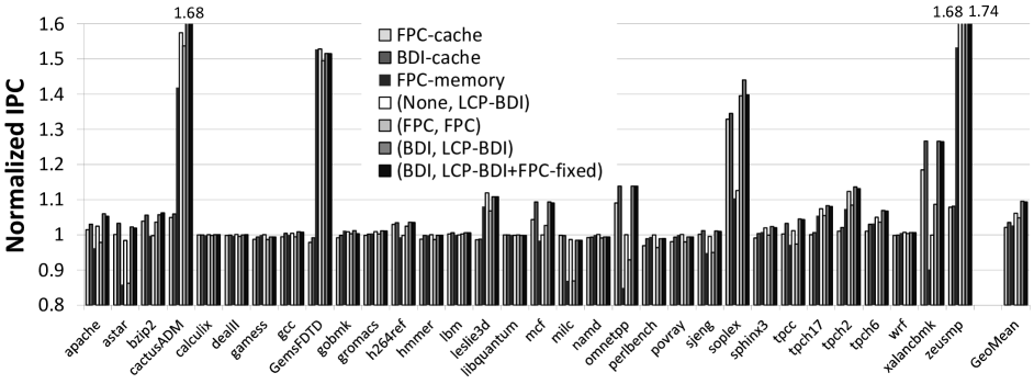
First, the performance improvement of combined LLC and DRAM compression is greater than that of LLC-only or DRAM-only compression alone. For example, LCP-BDI improves performance by 6.1%, whereas (BDI, LCP-BDI) improves performance by 9.5%. Intuitively, this is due to the orthogonality of the benefits provided by cache compression (which retains more cache lines that otherwise would have been evicted) and DRAM compression (which brings in more cache lines that would otherwise have required separate memory transfers on the main memory bus). We conclude that main memory and cache compression frameworks integrate well and complement each other.
Second, a high compression ratio does not always imply an improvement in performance. For example, while GemsFDTD is an application with a highly compressible working set in both the cache and DRAM, its performance does not improve with LLC-only compression schemes (due to the extra decompression latency), but improves significantly with DRAM-only compression schemes. In contrast, LLC-only compression is beneficial for omnetpp, whereas DRAM-only compression is not. This difference across applications can be explained by the difference in their memory access patterns. We observe that when temporal locality is critical for the performance of an application (e.g., omnetpp and xalancbmk), then cache compression schemes are typically more helpful. On the other hand, when applications have high spatial locality and less temporal locality (e.g., GemsFDTD has an overwhelmingly streaming access pattern with little reuse), they benefit significantly from the bandwidth compression provided by the LCP-based schemes. Hence, if the goal is to improve performance of a wide variety of applications, which may have a mix of temporal and spatial locality, our results suggest that employing both memory and cache compression using our LCP-based designs are the best option. We conclude that combined LLC and DRAM compression that takes advantage of our main memory compression framework improves the performance of a wide variety of applications.
7.1.2 Effect on Bus Bandwidth
When cache blocks and DRAM pages are compressed, the traffic between the LLC and DRAM can also be compressed. This can have multiple positive effects: i) reduction in the average latency of memory accesses, which can lead to improvement in the overall system performance, ii) decrease in the bus energy consumption due to the decrease in the number of transfers.
Figure 7.2 shows the reduction in main memory bandwidth between LLC and DRAM (in terms of bytes per kiloinstruction, normalized to a system with no compression) using different compression designs. Two major observations are in order.
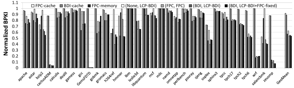
First, DRAM compression schemes are more effective in reducing bandwidth usage than cache compression schemes. This is because cache-only compression schemes reduce bandwidth consumption by reducing the number of LLC misses but they cannot reduce the bandwidth required to transfer a cache line from main memory. Overall, combined cache-DRAM compression schemes such as (FPC, FPC) and (BDI, LCP-BDI+FPC-fixed) decrease bandwidth consumption by more than 46%, by combining the reduction in both LLC misses and bandwidth required to transfer each cache line.
Second, there is a strong correlation between bandwidth compression and performance improvement (Figure 7.1). Applications that show a significant reduction in bandwidth consumption (e.g., GemsFDFD, cactusADM, soplex, zeusmp, leslie3d, tpc*) also see large performance improvements. There are some noticeable exceptions to this observation, e.g., h264ref, wrf and bzip2. Although the memory bus traffic is compressible in these applications, main memory bandwidth is not the bottleneck for their performance.
7.1.3 Effect on Energy
By reducing the number of data transfers on the memory bus, a compressed cache and main memory design also reduces the energy consumption of the memory bus. Figure 7.3 shows the reduction in consumed energy111Normalized to the energy of the baseline system with no compression. by the main memory bus with different compression designs. We observe that DRAM compression designs outperform cache compression designs, and LCP-based designs provide higher reductions than previous mechanisms for main memory compression. The largest energy reduction, 33% on average, is achieved by combined cache compression and LCP-based main memory compression mechanisms, i.e., (BDI, LCP-BDI) and (BDI, LCP-BDI+FPC-fixed). Even though we do not evaluate full system energy due to simulation infrastructure limitations, such a large reduction in main memory bus energy consumption can have a significant impact on the overall system energy, especially for memory-bandwidth-intensive applications. We conclude that our framework for main memory compression can enable significant energy savings, especially when compression is applied in both the last level cache and main memory.
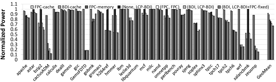
Chapter 8 Conclusions and Future Work
Memory hierarchies play a significant role in the performance and energy efficiency of many modern systems, from mobile devices to data centers and supercomputers. Unfortunately, the limited resources of these memory hierarchies are not always utilized efficiently. One of these sources of inefficiency is redundancy in the data that is stored and transferred. We observe that this redundancy can be efficiently explored using hardware-based data compression. In Chapter 2, we described what are the key challenges against making hardware-based data compression practical across major layers of the memory hierarchy: caches, main memory, and on-chip/off-chip buses.
In this dissertation, we proposed three major sets of solution to make hardware-based data compression efficient and practical in the context of all three layers of the memory hierarchy. First, we observed that a simple and fast, yet efficient compression algorithm can make data compression practical even for on-chip caches. In Chapter 3, we described such an algorithm, called Base-Delta-Immediate Compression, and a corresponding on-chip cache design to support data compression. The performance benefits observed are on-par with the performance benefits of doubling the cache size. Then, in Chapter 4, we showed that compressed block size can be sometimes indicative of data reuse and can be efficiently used as a new dimension in cache management decisions. The performance benefits of our proposed compression-aware mechanism which takes into account compressed block size in making cache replacement and insertion decisions, results in performance on-par with that provided by doubling the cache size. Overall, both cache compression and compression-aware replacement policies using compressed block size deliver performance on par with that of a conventional cache with 4 capacity.
Second, we proposed a new main memory compression framework, called Linearly Compressed Pages (LCP), that can provide low-overhead support for data compression in memory with different compression algorithms, to achieve higher effective memory capacity (69% on average) and higher off-chip bandwidth (24% on average). LCP improves performance by 6%/14%/11% for single-/two-/four-core workloads, relative to a system without main memory compression.
Third, we observed that there is a high potential for bandwidth compression for modern GPGPU applications. However, in order to realize this potential in an energy efficient manner, a new problem—the significant increase in bit flips (bit toggles) due to compressed data transfers on the interconnect—needs to be properly addressed. This increase is so high that it can lead to a 2.1 average increase in the consumed energy by the on-chip communication channel. We showed two major potential solutions to this problem, called Energy Control and Metadata Consolidation, which can preserve most of the benefits of compression without significant increase in energy consumption due to the bit toggle problem.
8.1 Future Work Directions
This dissertation on data compression significantly advances this subfield of computer architecture, but as it commonly happens, also highlights some completely new problems and opportunities. We conclude our dissertation by describing three such opportunities.
8.1.1 Compiler-Assisted Data Compression
One problem is the dependence of the existing compression algorithms on how the application data structures are mapped to main memory and on-chip caches (as we show in Chapter 3). For example, if pointer-like values are allocated side by side, they have a higher chance to be compressed well with BDI compression algorithm, but putting together (e.g., in the same cache line) a pointer and a boolean value would obviously lead to higher dynamic range, and hence lower compressibility. The latter frequently happens when arrays or lists of structs are defined in the program with different types mixed together. For applications with such data types, we want to allocate objects such that the spatial locality of similar-valued members is preserved. More precisely, we would like to split an object up into respective members and allocate space for those members based on what kinds of values they hold. These decisions of splitting and allocation may be made during compile time or runtime, depending on the implementation. Compression ratio improves from using members with similar value-types that are pooled (allocated) together and our preliminary studies already show a significant potential of such an approach. We aim to extend this idea to improve the compressibility of main memory pages that suffer from mixing data of very different types.
8.1.2 Data Compression for Non-Volatile Memories
LCP [184] main memory compression design was built on top of commodity DRAM main memory, but data compression is fundamentally independent of the technology that was used to build main memory. In our work, we aim to investigate the potential of extending LCP to other emerging non-volatile memory technologies (e.g., PCM [188, 125, 127, 126, 261, 249, 197], STT-MRAM [80, 123], RRAM [248]) and hybrid memory technologies (e.g., [157, 260, 50, 193, 196]). We expect that longer access/write latencies of these emerging memory technologies will allow the system designs to use more aggressive compression algorithms, and hence the capacity benefits of LCP-based designs can increase even further.
8.1.3 New Efficient Representations for Big Data
Many modern applications, such as machine learning applications, applications from the bioinformatics field, modern databases etc., operate on data sets that significantly exceed the available main memory. At the same time, these applications do not always require the full precision or accuracy in computation, as their input data are already significantly imprecise or noisy. In our future work, we would like to investigate the potential of partially replacing the accesses to the huge data sets in these applications with the accesses to their much smaller representations or signatures. The key idea is to build a lower-resolution representation of the data set, keep it up-to-date in main memory, and refer to it when information to this data set is missing in the main memory. We then dynamically monitor whether the application meets its desired quality of output, and update the aggressiveness of our speculation accordingly. Our related work in recovery-free value prediction using approximate loads [231, 258, 257] hints that this can be significant promise toward this direction of research.
Other Works of This Author
I have been actively involved in research projects outside the scope of my thesis.
Systems. I worked on web search systems for mobile phones where users’ interest in certain trending events can be predicted and efficiently prefetched to extend the phone’s battery life [182]. Previously, I also worked on improving the compile time of existing compilers with machine learning techniques that can predict which optimizations are actually useful for performance [178].
Main Memory. In collaboration with Vivek Seshadri, I proposed several ways of better utilizing existing DRAM-based main memories: (i) fast bulk data operations like copying and memory initialization using RowClone [207], and (ii) an enhanced virtual memory framework that enables fine-grained memory management [210]. In collaboration with Donghyuk Lee, I worked on (i) reducing the latency of existing DRAM memories [133], and (ii) increasing the bandwidth available for existing (and future) 3D stacking designs [132]. In collaboration with Hasan Hassan, I also worked on reducing DRAM latency by exploiting our new observation that many DRAM rows can be accessed significantly faster since they have sufficient amount of charge left [77]. In collaboration with Kevin Chang, I investigated the potential of reducing different DRAM timing parameters to decrease its latency and their effect on the error rate [35].
GPUs. In collaboration with Nandita Vijaykumar, I worked on new ways of utilizing existing GPU resources through flexible data compression [242, 243] and virtualization with oversubscription [241].
Bibliography
- [1] NVIDIA GeForce GTX 980 Review. http://www.anandtech.com/show/8526/nvidia-geforce-gtx-980-review/3.
- [2] T. Aarnio, C. Brunelli, and T. Viitanen. Efficient floating-point texture decompression. In System on Chip (SoC), 2010 International Symposium on, 2010.
- [3] Bulent Abali, Hubertus Franke, Dan E. Poff, Robert A. Saccone Jr., Charles O. Schulz, Lorraine M. Herger, and T. Basil Smith. Memory Expansion Technology (MXT): Software Support and Performance. IBM J.R.D., 2001.
- [4] Marc Abrams, Charles R. Standridge, Ghaleb Abdulla, Edward A. Fox, and Stephen Williams. Removal Policies in Network Caches for World-Wide Web Documents. In SIGCOMM, 1996.
- [5] Kartik K. Agaram, StephenW. Keckler, Calvin Lin, and Kathryn S. McKinley. Decomposing Memory Performance: Data Structures and Phases. In ISMM-5, 2006.
- [6] Jin-Hong Ahn, Bong-Hwa Jeong, Saeng-Hwan Kim, Shin-Ho Chu, Sung-Kwon Cho, Han-Jin Lee, Min-Ho Kim, Sang-Il Park, Sung-Won Shin, Jun-Ho Lee, Bong-Seok Han, Jae-Keun Hong, Moran P.B., and Yong-Tak Kim. Adaptive self refresh scheme for battery operated high-density mobile DRAM applications. In ASSCC, 2006.
- [7] Junwhan Ahn, Sungpack Hong, Sungjoo Yoo, Onur Mutlu, and Kiyoung Choi. A Scalable Processing-in-memory Accelerator for Parallel Graph Processing. In Proceedings of the 42Nd Annual International Symposium on Computer Architecture, ISCA ’15, 2015.
- [8] Junwhan Ahn, Sungjoo Yoo, Onur Mutlu, and Kiyoung Choi. PIM-enabled Instructions: A Low-overhead, Locality-aware Processing-in-memory Architecture. In Proceedings of the 42Nd Annual International Symposium on Computer Architecture, ISCA ’15, 2015.
- [9] B. Akin, F. Franchetti, and J. C. Hoe. Data reorganization in memory using 3D-stacked DRAM. In 2015 ACM/IEEE 42nd Annual International Symposium on Computer Architecture (ISCA), 2015.
- [10] Alaa R. Alameldeen and David A. Wood. Adaptive Cache Compression for High-Performance Processors. In ISCA, 2004.
- [11] Alaa R. Alameldeen and David A. Wood. Frequent Pattern Compression: A Significance-Based Compression Scheme for L2 Caches. Tech. Rep., 2004.
- [12] Alaa R. Alameldeen and David A. Wood. Interactions Between Compression and Prefetching in Chip Multiprocessors. In HPCA, 2007.
- [13] Guido Araujo, Paulo Centoducatte, Mario Cartes, and Ricardo Pannain. Code compression based on operand factorization. In Proceedings of the 31st Annual ACM/IEEE International Symposium on Microarchitecture, MICRO 31, 1998.
- [14] Arc Technica. OS X 10.9 Mavericks: The Ars Technica Review. http://arstechnica.com/apple/2013/10/os-x-10-9/17/, October 2013.
- [15] Angelos Arelakis, Fredrik Dahlgren, and Per Stenstrom. HyComp: A Hybrid Cache Compression Method for Selection of Data-type-specific Compression Methods. In Proceedings of the 48th International Symposium on Microarchitecture, MICRO-48, 2015.
- [16] Angelos Arelakis and Per Stenstrom. SC2: A Statistical Compression Cache Scheme. In ISCA, 2014.
- [17] Rachata Ausavarungnirun, Kevin Kai-Wei Chang, Lavanya Subramanian, Gabriel H. Loh, and Onur Mutlu. Staged Memory Scheduling: Achieving High Performance and Scalability in Heterogeneous Systems. In Proceedings of the 39th Annual International Symposium on Computer Architecture, ISCA ’12, 2012.
- [18] Manu Awasthi, David W. Nellans, Kshitij Sudan, Rajeev Balasubramonian, and Al Davis. Handling the problems and opportunities posed by multiple on-chip memory controllers. In Proceedings of the 19th International Conference on Parallel Architectures and Compilation Techniques, PACT ’10, 2010.
- [19] Oreoluwatomiwa O. Babarinsa and Stratos Idreos. Jafar: Near-data processing for databases. In Proceedings of the 2015 ACM SIGMOD International Conference on Management of Data, SIGMOD ’15, 2015.
- [20] Seungcheol Baek, Hyung G. Lee, Chrysostomos Nicopoulos, Junghee Lee, and Jongman Kim. ECM: Effective Capacity Maximizer for High-Performance Compressed Caching. In HPCA-19, 2013.
- [21] Hyokyung Bahn, Sam H. Noh, Sang Lyul Min, and Kern Koh. Using Full Reference History for Efficient Document Replacement in Web Caches. In USITS, 1999.
- [22] Ali Bakhoda, George L. Yuan, Wilson W. L. Fung, Henry Wong, and Tor M. Aamodt. Analyzing CUDA Workloads Using a Detailed GPU Simulator. In ISPASS, 2009.
- [23] Saisanthosh Balakrishnan and Gurindar S. Sohi. Exploiting Value Locality in Physical Register Files. In MICRO-36, 2003.
- [24] Rajeev Balasubramonian, Naveen Muralimanohar, Karthik Ramani, and Venkatanand Venkatachalapathy. Microarchitectural Wire Management for Performance and Power in Partitioned Architectures. In HPCA, 2005.
- [25] Bradford M. Beckmann and David A. Wood. TLC: Transmission line caches. In MICRO, 2003.
- [26] L. A. Belady. A study of replacement algorithms for a virtual-storage computer. IBM Syst. J., 5(2):78–101, June 1966.
- [27] Emery David Berger. Memory Management for High-Performance Applications. PhD thesis, 2002.
- [28] Bryan Black, Murali Annavaram, Ned Brekelbaum, John DeVale, Lei Jiang, Gabriel H. Loh, Don McCaule, Pat Morrow, Donald W. Nelson, Daniel Pantuso, Paul Reed, Jeff Rupley, Sadasivan Shankar, John Shen, and Clair Webb. Die Stacking (3D) Microarchitecture. In MICRO, 2006.
- [29] Mahdi Nazm Bojnordi and Engin Ipek. DESC: Energy-efficient Data Exchange Using Synchronized Counters. In MICRO, 2013.
- [30] Amirali Boroumand, Saugata Ghose, Minesh Patel, Hasan Hassan, Brandon Lucia, Kevin Hsieh, Krishna T Malladi, Hongzhong Zheng, and Onur Mutlu. LazyPIM: an Efficient Cache Coherence Mechanism for Processing-in-memory. In Computer Architecture Letters, 2016.
- [31] M. Burtscher et al. A quantitative study of irregular programs on gpus. In IISWC, 2012.
- [32] P Cao and S Irani. Cost-Aware WWW Proxy Caching Algorithms. In USENIX Symposium on ITS, 1997.
- [33] K. K. Chang, P. J. Nair, D. Lee, S. Ghose, M. K. Qureshi, and O. Mutlu. Low-Cost Inter-Linked Subarrays (LISA): Enabling fast inter-subarray data movement in DRAM. In 2016 IEEE International Symposium on High Performance Computer Architecture (HPCA), 2016.
- [34] K. K. W. Chang, D. Lee, Z. Chishti, A. R. Alameldeen, C. Wilkerson, Y. Kim, and O. Mutlu. Improving DRAM performance by parallelizing refreshes with accesses. In 2014 IEEE 20th International Symposium on High Performance Computer Architecture (HPCA), 2014.
- [35] Kevin K. Chang, Abhijith Kashyap, Hasan Hassan, Saugata Ghose, Kevin Hsieh, Donghyuk Lee, Tianshi Li, Gennady Pekhimenko, Samira Manabi Khan, and Onur Mutlu. Understanding Latency Variation in Modern DRAM Chips: Experimental Characterization, Analysis, and Optimization. In Proceedings of the 2016 ACM SIGMETRICS International Conference on Measurement and Modeling of Computer Science, 2016.
- [36] S. Che et al. Rodinia: A Benchmark Suite for Heterogeneous Computing. In IISWC, 2009.
- [37] Jie Chen and William Watson Iii. Multi-threading performance on commodity multi-core processors. In Proceedings of HPCAsia, 2007.
- [38] Xi Chen, Lei Yang, R.P. Dick, Li Shang, and H. Lekatsas. C-pack: A high-performance microprocessor cache compression algorithm. TVLSI, 2010.
- [39] K Cheng and Y Kambayashi. A Size-Adjusted and Popularity-Aware LRU Replacement Algorithm for Web Caching. In COMPSAC-24, 2000.
- [40] David Cheriton, Amin Firoozshahian, Alex Solomatnikov, John P. Stevenson, and Omid Azizi. HICAMP: Architectural Support for Efficient Concurrency-safe Shared Structured Data Access. In Proceedings of the Seventeenth International Conference on Architectural Support for Programming Languages and Operating Systems, ASPLOS XVII, 2012.
- [41] Lars Ræder Clausen, Ulrik Pagh Schultz, Charles Consel, and Gilles Muller. Java bytecode compression for low-end embedded systems. volume 22, May 2000.
- [42] Keith D. Cooper and Nathaniel McIntosh. Enhanced code compression for embedded risc processors. In Proceedings of the ACM SIGPLAN 1999 Conference on Programming Language Design and Implementation, PLDI ’99, 1999.
- [43] Elliott Cooper-Balis, Paul Rosenfeld, and Bruce Jacob. Buffer-On-Board Memory Systems. In ISCA, 2012.
- [44] Reetuparna Das, Rachata Ausavarungnirun, Onur Mutlu, Akhilesh Kumar, and Mani Azimi. Application-to-core Mapping Policies to Reduce Memory Interference in Multi-core Systems. In Proceedings of the 21st International Conference on Parallel Architectures and Compilation Techniques, PACT ’12, 2012.
- [45] Reetuparna Das, Asit K. Mishra, Chrysostomos Nicopoulos, Dongkook Park, Vijaykrishnan Narayanan, Ravishankar R. Iyer, Mazin S. Yousif, and Chita R. Das:. Performance and power optimization through data compression in Network-on-Chip architectures. In HPCA, 2008.
- [46] Reetuparna Das, Asit K. Mishra, Chrysostomos Nicopoulos, Dongkook Park, Vijaykrishnan Narayanan, Ravishankar R. Iyer, Mazin S. Yousif, and Chita R. Das. Performance and power optimization through data compression in Network-on-Chip architectures. In HPCA, 2008.
- [47] Howard David, Chris Fallin, Eugene Gorbatov, Ulf R. Hanebutte, and Onur Mutlu. Memory power management via dynamic voltage/frequency scaling. In ICAC, 2011.
- [48] Rodrigo S. de Castro, Alair Pereira do Lago, and Dilma Da Silva. Adaptive Compressed Caching: Design and Implementation. In SBAC-PAD, 2003.
- [49] Peter J. Denning. The Working Set Model for Program Behavior. Commun. ACM, 1968.
- [50] Gaurav Dhiman, Raid Ayoub, and Tajana Rosing. Pdram: A hybrid pram and dram main memory system. In Proceedings of the 46th Annual Design Automation Conference, DAC ’09, 2009.
- [51] Chen Ding and Yutao Zhong. Predicting Whole-program Locality Through Reuse Distance Analysis. In PLDI, 2003.
- [52] Fred Douglis. The Compression Cache: Using On-line Compression to Extend Physical Memory. In Winter USENIX Conference, 1993.
- [53] Julien Dusser, Thomas Piquet, and André Seznec. Zero-content Augmented Caches. In ICS, 2009.
- [54] Julien Dusser, Thomas Piquet, and André Seznec. Zero-Content Augmented Caches. In ICS, 2009.
- [55] Eiman Ebrahimi, Chang Joo Lee, Onur Mutlu, and Yale N. Patt. Fairness via Source Throttling: A Configurable and High-performance Fairness Substrate for Multi-core Memory Systems. In ASPLOS XV, 2010.
- [56] Eiman Ebrahimi, Rustam Miftakhutdinov, Chris Fallin, Chang Joo Lee, José A. Joao, Onur Mutlu, and Yale N. Patt. Parallel Application Memory Scheduling. In Proceedings of the 44th Annual IEEE/ACM International Symposium on Microarchitecture, MICRO-44, 2011.
- [57] Magnus Ekman and Per Stenstrom. A Robust Main-Memory Compression Scheme. In ISCA, 2005.
- [58] Hala ElAarag and Sam Romano. Comparison of function based web proxy cache replacement strategies. In SPECTS-12, 2009.
- [59] D. G. Elliott, W. M. Snelgrove, and M. Stumm. Computational RAM: A Memory-simd Hybrid And Its Application To DSP. In Custom Integrated Circuits Conference, 1992., Proceedings of the IEEE 1992, May 1992.
- [60] Jens Ernst, William Evans, Christopher W. Fraser, Todd A. Proebsting, and Steven Lucco. Code compression. In Proceedings of the ACM SIGPLAN 1997 Conference on Programming Language Design and Implementation, PLDI ’97, 1997.
- [61] S. Eyerman and L. Eeckhout. System-level performance metrics for multiprogram workloads. IEEE Micro, 28(3):42–53, May 2008.
- [62] A. Farmahini-Farahani, J. H. Ahn, K. Morrow, and N. S. Kim. Nda: Near-dram acceleration architecture leveraging commodity dram devices and standard memory modules. In 2015 IEEE 21st International Symposium on High Performance Computer Architecture (HPCA), 2015.
- [63] A. Farmahini-Farahani, J. H. Ahn, K. Morrow, and N. S. Kim. Nda: Near-dram acceleration architecture leveraging commodity dram devices and standard memory modules. In 2015 IEEE 21st International Symposium on High Performance Computer Architecture (HPCA), 2015.
- [64] Matthew Farrens and Arvin Park. Dynamic Base Register Caching: A Technique for Reducing Address Bus Width. In ISCA, 1991.
- [65] Basilio B. Fraguela, Jose Renau, Paul Feautrier, David Padua, and Josep Torrellas. Programming the FlexRAM Parallel Intelligent Memory System. In Proceedings of the Ninth ACM SIGPLAN Symposium on Principles and Practice of Parallel Programming, PPoPP ’03, 2003.
- [66] Gabe Aul. Announcing Windows 10 Insider Preview Build 10525. https://blogs.windows.com/windowsexperience/2015/08/18/announcing-windows-10-insider-preview-build-10525/, August 2015.
- [67] M. Gao, G. Ayers, and C. Kozyrakis. Practical Near-Data Processing for In-Memory Analytics Frameworks. In 2015 International Conference on Parallel Architecture and Compilation (PACT), 2015.
- [68] Mingyu Gao and Christos Kozyrakis. HRL: efficient and flexible reconfigurable logic for near-data processing. In 2016 IEEE International Symposium on High Performance Computer Architecture, HPCA 2016, Barcelona, Spain, March 12-16, 2016, 2016.
- [69] Maya Gokhale, Bill Holmes, and Ken Iobst. Processing in Memory: The Terasys Massively Parallel PIM Array. Computer, 28(4):23–31, 1995.
- [70] R. Gonzalez and M. Horowitz. Energy Dissipation in General Purpose Microprocessors. JSCC, 1996.
- [71] Google. CompCache. https://code.google.com/archive/p/compcache/, January 2015.
- [72] Erik G. Hallnor and Steven K. Reinhardt. A Fully Associative Software-Managed Cache Design. In ISCA-27, 2000.
- [73] Erik G. Hallnor and Steven K. Reinhardt. A Unified Compressed Memory Hierarchy. In HPCA, 2005.
- [74] D. W. Hammerstrom and E. S. Davidson. Information content of CPU memory referencing behavior. ISCA-4, 1977.
- [75] Milad Hashemi, Khubaib, Eiman Ebrahimi, Onur Mutlu, and Yale N. Patt. Accelerating Dependent Cache Misses with an Enhanced Memory Controller. In ISCA-43, 2016.
- [76] Milad Hashemi, Onur Mutlu, and Yale Patt. Continuous Runahead: Transparent Hardware Acceleration for Memory Intensive Workloads. In MICRO, 2016.
- [77] Hasan Hassan, Gennady Pekhimenko, Nandita Vijaykumar, Vivek Seshadri, Donghyuk Lee, Oguz Ergin, and Onur Mutlu. ChargeCache: Reducing DRAM Latency by Exploiting Row Access Locality. In HPCA, 2016.
- [78] Mitchell Hayenga, Andrew Nere, and Mikko Lipasti. MadCache: A PC-aware Cache Insertion Policy. In JWAC, 2010.
- [79] B. He et al. Mars: A MapReduce Framework on Graphics Processors. In PACT, 2008.
- [80] M. Hosomi, H. Yamagishi, T. Yamamoto, K. Bessho, Y. Higo, K. Yamane, H. Yamada, M. Shoji, H. Hachino, C. Fukumoto, H. Nagao, and H. Kano. A novel nonvolatile memory with spin torque transfer magnetization switching: spin-ram. In Electron Devices Meeting, 2005. IEDM Technical Digest. IEEE International, pages 459–462, 2005.
- [81] Kevin Hsieh, Eiman Ebrahimi, Gwangsun Kim, Niladrish Chatterjee, Mike O’Connor, Nandita Vijaykumar, Onur Mutlu, and Stephen W. Keckler. Transparent Oloading and Mapping (TOM): Enabling Programmer-Transparent Near-Data Processing in GPU Systems. In Proceedings of the 43th Annual International Symposium on Computer Architecture, ISCA ’16, 2016.
- [82] Kevin Hsieh, Samira Khan, Nandita Vijaykumar, Kevin K. Chang, Amirali Boroumand, Saugata Ghose, and Onur Mutlu. Accelerating Pointer Chasing in 3D-Stacked Memory: Challenges, Mechanisms, Evaluation. In ICCD, 2016.
- [83] D.A. Huffman. A Method for the Construction of Minimum-Redundancy Codes. IRE, 1952.
- [84] Hybrid Memory Cube Consortium. HMC Specification 1.1, 2013.
- [85] Hybrid Memory Cube Consortium. HMC Specification 1.1, February 2014.
- [86] Hybrid Memory Cube Consortium. HMC Specification 2.0, 2014.
- [87] Hynix. 512M (16mx32) GDDR3 SDRAM hy5rs123235fp.
- [88] Hynix. Hynix GDDR5 SGRAM Part H5GQ1H24AFR Revision 1.0.
- [89] Sorin Iacobovici, Lawrence Spracklen, Sudarshan Kadambi, Yuan Chou, and Santosh G. Abraham. Effective stream-based and execution-based data prefetching. ICS ’04, 2004.
- [90] IBM. AIX 6.1 Active Memory Expansion, January 2015.
- [91] Intel Corporation. Intel 64 and IA-32 Architectures Software Developer’s Manual, 2013.
- [92] Ciji Isen and Lizy Kurian John. ESKIMO: Energy savings using Semantic Knowledge of Inconsequential Memory Occupancy for DRAM subsystem. In MICRO, 2009.
- [93] Mafijul Md. Islam and Per Stenstrom. Zero-Value Caches: Cancelling Loads that Return Zero. In PACT, 2009.
- [94] Mafijul Md Islam and Per Stenstrom. Characterization and exploitation of narrow-width loads: the narrow-width cache approach. CASES ’10, 2010.
- [95] A.N. Jacobvitz, R. Calderbank, and D.J. Sorin. Coset coding to extend the lifetime of memory. In HPCA, 2013.
- [96] Aamer Jaleel, Kevin B. Theobald, Simon C. Steely, Jr., and Joel Emer. High Performance Cache Replacement Using Re-reference Interval Prediction (RRIP). In ISCA-37, 2010.
- [97] JEDEC. DDR4 SDRAM Standard, 2012.
- [98] JEDEC. Graphics Double Data Rate (GDDR5) SGRAM Standard. Standard No. JESD212B.01, 2013.
- [99] JEDEC. High Bandwidth Memory (HBM) DRAM. Standard No. JESD235, 2013.
- [100] JEDEC. JESD235 High Bandwidth Memory (HBM) DRAM, October 2013.
- [101] JEDEC. Wide I/O 2 (WideIO2). Standard No. JESD229-2, 2014.
- [102] JEDEC. Standard No. 79-3F. DDR3 SDRAM Specification, July 2012. July 2009.
- [103] Yuho Jin, Ki Hwan Yum, and Eun Jung Kim. Adaptive Data Compression for High-Performance Low-Power On-Chip Networks. In MICRO-41, 2008.
- [104] A. Jog et al. Orchestrated Scheduling and Prefetching for GPGPUs. In ISCA, 2013.
- [105] Adwait Jog, Onur Kayiran, Nachiappan Chidambaram Nachiappan, Asit K. Mishra, Mahmut T. Kandemir, Onur Mutlu, Ravishankar Iyer, and Chita R. Das. OWL: cooperative thread array aware scheduling techniques for improving GPGPU performance. In ASPLOS, 2013.
- [106] Adwait Jog, Onur Kayiran, Ashutosh Pattnaik, Mahmut T. Kandemir, Onur Mutlu, Ravishankar Iyer, and Chita R. Das. Exploiting Core Criticality for Enhanced GPU Performance. In Proceedings of the 2016 ACM SIGMETRICS International Conference on Measurement and Modeling of Computer Science, SIGMETRICS ’16, 2016.
- [107] Teresa L. Johnson and Wen-mei W. Hwu. Run-time adaptive cache hierarchy management via reference analysis. In Proceedings of the 24th Annual International Symposium on Computer Architecture, ISCA ’97, 1997.
- [108] Teresa L. Johnson, Matthew C. Merten, and Wen-Mei W. Hwu. Run-time spatial locality detection and optimization. In Proceedings of the 30th Annual ACM/IEEE International Symposium on Microarchitecture, MICRO 30, 1997.
- [109] Uksong Kang et al. 8Gb 3D DDR3 DRAM Using Through-Silicon-Via Technology. In ISSCC, 2009.
- [110] Yi Kang, Wei Huang, Seung-Moon Yoo, D. Keen, Zhenzhou Ge, V. Lam, P. Pattnaik, and J. Torrellas. Flexram: toward an advanced intelligent memory system. In Computer Design, 1999. (ICCD ’99) International Conference on, 1999.
- [111] Scott Frederick Kaplan. Compressed caching and modern virtual memory simulation. PhD thesis, 1999.
- [112] Georgios Keramidas, Pavlos Petoumenos, and Stefanos Kaxiras. Cache Replacement Based on Reuse-Distance Prediction. In ICCD, 2007.
- [113] Samira Khan et al. The efficacy of error mitigation techniques for DRAM retention failures: a comparative experimental study. In SIGMETRICS, 2014.
- [114] Samira Manabi Khan, Alaa R. Alameldeen, Chris Wilkerson, Onur Mutlu, and Daniel A. Jiménez. Improving cache performance using read-write partitioning. In HPCA, 2014.
- [115] Mazen Kharbutli and Rami Sheikh. LACS: A Locality-Aware Cost-Sensitive Cache Replacement Algorithm. In Transactions on Computers, 2013.
- [116] Joohee Kim and Marios C. Papaefthymiou. Dynamic memory design for low data-retention power. In PATMOS, 2000.
- [117] Jungrae Kim, Michael Sullivan, Esha Choukse, and Mattan Erez. Bit-Plane Compression: Transforming Data for Better Compression in Many-core Architectures. In ISCA, 2016.
- [118] Yoongu Kim et al. ATLAS: A scalable and high-performance scheduling algorithm for multiple memory controllers. In HPCA-16, 2010.
- [119] Yoongu Kim, M. Papamichael, O. Mutlu, and M. Harchol-Balter. Thread Cluster Memory Scheduling: Exploiting Differences in Memory Access Behavior. In MICRO-43, 2010.
- [120] Yoongu Kim, Vivek Seshadri, Donghyuk Lee, Jamie Liu, and Onur Mutlu. A Case for Exploiting Subarray-Level Parallelism (SALP) in DRAM. In ISCA, 2012.
- [121] Peter M. Kogge. Execube-a new architecture for scaleable mpps. In Proceedings of the 1994 International Conference on Parallel Processing - Volume 01, ICPP ’94, 1994.
- [122] Michael Kozuch and Andrew Wolfe. Compression of embedded system programs. In International Conference on Computer Design, ICCD ’94, 1994.
- [123] Emre Kultursay, Mahmut Kandemir, Anand Sivasubramaniam, and Onur Mutlu. Evaluating STT-RAM as an energy-efficient main memory alternative. In ISPASS, 2013.
- [124] Chris Lattner and Vikram Adve. Transparent Pointer Compression for Linked Data Structures. In Proceedings of the ACM Workshop on Memory System Performance (MSP’05), 2005.
- [125] Benjamin C. Lee, Engin Ipek, Onur Mutlu, and Doug Burger. Architecting Phase Change Memory As a Scalable Dram Alternative. In Proceedings of the 36th Annual International Symposium on Computer Architecture, ISCA ’09, 2009.
- [126] Benjamin C. Lee, Engin Ipek, Onur Mutlu, and Doug Burger. Phase Change Memory Architecture and the Quest for Scalability. Commun. ACM, 53(7), 2010.
- [127] Benjamin C. Lee, Ping Zhou, Jun Yang, Youtao Zhang, Bo Zhao, Engin Ipek, Onur Mutlu, and Doug Burger. Phase-Change Technology and the Future of Main Memory. IEEE Micro, 30(1), January 2010.
- [128] Chang Joo Lee, Onur Mutlu, Veynu Narasiman, and Yale N. Patt. Prefetch-Aware DRAM Controllers. In Proceedings of the 41st Annual IEEE/ACM International Symposium on Microarchitecture, MICRO 41, 2008.
- [129] Chang Joo Lee, Veynu Narasiman, Eiman Ebrahimi, Onur Mutlu, and Yale N. Patt. DRAM-Aware Last-Level Cache Writeback: Reducing Write-Caused Interference in Memory Systems. In HPS Technical Report, TR-HPS-2010-002, 2010.
- [130] Chang Joo Lee, Veynu Narasiman, Onur Mutlu, and Yale N. Patt. Improving memory bank-level parallelism in the presence of prefetching. In Proceedings of the 42Nd Annual IEEE/ACM International Symposium on Microarchitecture, MICRO 42, 2009.
- [131] Dong Uk Lee, Kyung Whan Kim, Kwan Weon Kim, Hongjung Kim, Ju Young Kim, Young Jun Park, Jae Hwan Kim, Dae Suk Kim, Heat Bit Park, Jin Wook Shin, Jang Hwan Cho, Ki Hun Kwon, Min Jeong Kim, Jaejin Lee, Kun Woo Park, Byongtae Chung, and Sungjoo Hong. 25.2 A 1.2V 8Gb 8-Channel 128GB/s High-Bandwidth Memory (HBM) Stacked DRAM with Effective Microbump I/O Test Methods Using 29nm Process and TSV. In ISSCC, 2014.
- [132] Donghyuk Lee, Saugata Ghose, Gennady Pekhimenko, Samira Khan, and Onur Mutlu. Simultaneous Multi-Layer Access: Improving 3D-Stacked Memory Bandwidth at Low Cost. In TACO, 2016.
- [133] Donghyuk Lee, Yoongu Kim, Gennady Pekhimenko, Samira Manabi Khan, Vivek Seshadri, Kevin Kai-Wei Chang, and Onur Mutlu. Adaptive-latency DRAM: Optimizing DRAM timing for the common-case. In HPCA, 2015.
- [134] Donghyuk Lee, Yoongu Kim, Vivek Seshadri, Jamie Liu, Lavanya Subramanian, and Onur Mutlu. Tiered-latency DRAM: A low latency and low cost DRAM architecture. In HPCA, 2013.
- [135] Joo Hwan Lee, Jaewoong Sim, and Hyesoon Kim. Bssync: Processing near memory for machine learning workloads with bounded staleness consistency models. In Proceedings of the 2015 International Conference on Parallel Architecture and Compilation (PACT), PACT ’15, 2015.
- [136] C. Lefurgy, E. Piccininni, and T. Mudge. Reducing code size with run-time decompression. In High Performance Computer Architecture, 2000.
- [137] Charles Lefurgy, Peter Bird, I-Cheng Chen, and Trevor Mudge. Improving code density using compression techniques. In Proceedings of the 30th Annual ACM/IEEE International Symposium on Microarchitecture, MICRO 30, 1997.
- [138] Charles Lefurgy et al. Energy Management for Commercial Servers. In IEEE Computer, 2003.
- [139] Charles Lefurgy, Eva Piccininni, and Trevor Mudge. Evaluation of a high performance code compression method. In Proceedings of the 32Nd Annual ACM/IEEE International Symposium on Microarchitecture, MICRO 32, 1999.
- [140] Haris Lekatsas, Jörg Henkel, and Wayne Wolf. Code compression for low power embedded system design. In Proceedings of the 37th Annual Design Automation Conference, DAC ’00, 2000.
- [141] J. Leng et al. GPUWattch: Enabling Energy Optimizations in GPGPUs. In ISCA, 2013.
- [142] Chuanpeng Li, Chen Ding, and Kai Shen. Quantifying the Cost of Context Switch. In ExpCS, 2007.
- [143] S Li, Jung Ho Ahn, R.D. Strong, J.B. Brockman, D.M. Tullsen, and N.P Jouppi. McPAT: An Integrated Power, Area, and Timing Modeling Framework for Multicore and Manycore Architectures. MICRO-42, 2009.
- [144] Shuangchen Li, Cong Xu, Qiaosha Zou, Jishen Zhao, Yu Lu, and Yuan Xie. Pinatubo: A processing-in-memory architecture for bulk bitwise operations in emerging non-volatile memories. In Proceedings of the 53rd Annual Design Automation Conference, DAC ’16, 2016.
- [145] Chung-Hsiang Lin, Chia-Lin Yang, and Ku-Jei King. PPT: Joint Performance/Power/Thermal Management of DRAM Memory for Multi-core Systems. In ISLPED, 2009.
- [146] Jamie Liu, Ben Jaiyen, Yoongu Kim, Chris Wilkerson, and Onur Mutlu. An experimental study of data retention behavior in modern DRAM devices: implications for retention time profiling mechanisms. In The 40th Annual International Symposium on Computer Architecture, ISCA’13, 2013.
- [147] Jamie Liu, Ben Jaiyen, Richard Veras, and Onur Mutlu. RAIDR: Retention-Aware Intelligent DRAM Refresh. In Proceedings of the 39th Annual International Symposium on Computer Architecture, ISCA ’12, 2012.
- [148] Song Liu, B. Leung, A. Neckar, S.O. Memik, G. Memik, and N. Hardavellas. Hardware/software techniques for DRAM thermal management. In HPCA, 2011.
- [149] Song Liu, Karthik Pattabiraman, Thomas Moscibroda, and Benjamin G. Zorn. Flikker: saving DRAM refresh-power through critical data partitioning. In ASPLOS, 2011.
- [150] Gabriel H. Loh. 3D-Stacked Memory Architectures for Multi-core Processors. In ISCA, 2008.
- [151] Gabriel H. Loh. Extending the Effectiveness of 3D-Stacked DRAM Caches with an Adaptive Multi-Queue Policy. In MICRO, 2009.
- [152] Shih-Lien Lu, Ying-Chen Lin, and Chia-Lin Yang. Improving DRAM Latency with Dynamic Asymmetric Subarray. In Proceedings of the 48th International Symposium on Microarchitecture, MICRO-48, 2015.
- [153] Yixin Luo, Sriram Govindan, Bikash Sharma, Mark Santaniello, Justin Meza, Aman Kansal, Jie Liu, Badriddine Khessib, Kushagra Vaid, and Onur Mutlu. Characterizing application memory error vulnerability to optimize datacenter cost via heterogeneous-reliability memory. In Proceedings of the 2014 44th Annual IEEE/IFIP International Conference on Dependable Systems and Networks, DSN ’14, 2014.
- [154] Peter S. Magnusson, Magnus Christensson, Jesper Eskilson, Daniel Forsgren, Gustav Hållberg, Johan Högberg, Fredrik Larsson, Andreas Moestedt, and Bengt Werner. Simics: A Full System Simulation Platform. Computer, 35:50–58, February 2002.
- [155] Krishna T. Malladi, Frank A. Nothaft, Karthika Periyathambi, Benjamin C. Lee, Christos Kozyrakis, and Mark Horowitz. Towards Energy-Proportional Datacenter Memory with Mobile DRAM. In ISCA, 2012.
- [156] Mem-Sim. http://www.ece.cmu.edu/safari/tools.html.
- [157] Justin Meza, Jichuan Chang, HanBin Yoon, Onur Mutlu, and Parthasarathy Ranganathan. Enabling efficient and scalable hybrid memories using fine-granularity dram cache management. Computer Architecture Letters, 11(2):61–64, 2012.
- [158] Micron. DDR3 SDRAM System-Power Calculator, 2010.
- [159] Micron. 2Gb: x4, x8, x16, DDR3 SDRAM, 2012.
- [160] D. Molka, D. Hackenberg, R. Schone, and M.S. Muller. Memory performance and cache coherency effects on an Intel Nehalem multiprocessor system. In PACT, 2009.
- [161] P. Mosalikanti, C. Mozak, and N. Kurd. High performance DDR architecture in Intel Core processors using 32nm CMOS high-K metal-gate process. In VLSI-DAT, 2011.
- [162] Sai Prashanth Muralidhara, Lavanya Subramanian, Onur Mutlu, Mahmut Kandemir, and Thomas Moscibroda. Reducing Memory Interference in Multicore Systems via Application-aware Memory Channel Partitioning. In Proceedings of the 44th Annual IEEE/ACM International Symposium on Microarchitecture, MICRO-44, 2011.
- [163] Onur Mutlu. Memory scaling: A systems architecture perspective. 2013.
- [164] Onur Mutlu and Thomas Moscibroda. Stall-Time Fair Memory Access Scheduling for Chip Multiprocessors. In Proceedings of the 40th Annual IEEE/ACM International Symposium on Microarchitecture, MICRO 40, 2007.
- [165] Onur Mutlu and Thomas Moscibroda. Parallelism-Aware Batch Scheduling: Enhancing Both Performance and Fairness of Shared DRAM Systems. In Proceedings of the 35th Annual International Symposium on Computer Architecture, ISCA ’08, 2008.
- [166] Veynu Narasiman, Michael Shebanow, Chang Joo Lee, Rustam Miftakhutdinov, Onur Mutlu, and Yale N. Patt. Improving GPU Performance via Large Warps and Two-level Warp Scheduling. In MICRO, 2011.
- [167] Kyle J. Nesbit, Nidhi Aggarwal, James Laudon, and James E. Smith. Fair queuing memory systems. In Proceedings of the 39th Annual IEEE/ACM International Symposium on Microarchitecture, MICRO 39, 2006.
- [168] Tri M. Nguyen and David Wentzlaff. Morc: A manycore-oriented compressed cache. In Proceedings of the 48th International Symposium on Microarchitecture, MICRO-48, 2015.
- [169] NSF Press Release 12-060. NSF Leads Federal Efforts In Big Data. http://www.nsf.gov/news/news_summ.jsp?cntn_id=123607, March 2012.
- [170] NVIDIA. CUDA C/C++ SDK Code Samples, 2011.
- [171] Taku Ohsawa, Koji Kai, and Kazuaki Murakami. Optimizing the DRAM refresh count for merged DRAM/logic LSIs. In ISLPED, 1998.
- [172] Mark Oskin, Frederic T. Chong, and Timothy Sherwood. Active pages: A computation model for intelligent memory. In Proceedings of the 25th Annual International Symposium on Computer Architecture, ISCA ’98, 1998.
- [173] Harish Patil, Robert Cohn, Mark Charney, Rajiv Kapoor, Andrew Sun, and Anand Karunanidhi. Pinpointing Representative Portions of Large Intel Itanium Programs with Dynamic Instrumentation. MICRO-37, 2004.
- [174] David Patterson, Thomas Anderson, Neal Cardwell, Richard Fromm, Kimberly Keeton, Christoforos Kozyrakis, Randi Thomas, and Katherine Yelick. A case for intelligent ram. IEEE Micro, 17(2):34–44, 1997.
- [175] Ashutosh Pattnaik, Xulong Tang, Adwait Jog, Onur Kayiran, Asit K. Mishra, Mahmut T. Kandemir, Onur Mutlu, and Chita R. Das. Scheduling Techniques for GPU Architectures with Processing-In-Memory Capabilities. In PACT, 2016.
- [176] Gennady Pekhimenko, Evgeny Bolotin, Mike. O’Connor, Onur Mutlu, Todd. Mowry, and Stephen Keckler. Toggle-Aware Compression for GPUs. Computer Architecture Letters, 2015.
- [177] Gennady Pekhimenko, Evgeny Bolotin, Nandita. Vijaykumar, Onur Mutlu, Todd. Mowry, and Stephen Keckler. A Case for Toggle-Aware Compression for GPU Systems. In HPCA, 2016.
- [178] Gennady Pekhimenko and Angela Demke Brown. Efficient Program Compilation through Machine Learning Techniques. In iWAPT, 2009.
- [179] Gennady Pekhimenko and et al. Linearly Compressed Pages: A Main Memory Compression Framework with Low Complexity and Low Latency. In SAFARI Technical Report No. 2012-002, 2012.
- [180] Gennady Pekhimenko et al. Exploiting Compressed Block Size as an Indicator of Future Reuse. In SAFARI Technical Report No. 2013-003, 2013.
- [181] Gennady Pekhimenko, Tyler Huberty, Rui Cai, Onur Mutlu, Phillip B. Gibbons, Michael A. Kozuch, and Todd C. Mowry. Exploiting Compressed Block Size as an Indicator of Future Reuse. In HPCA, 2015.
- [182] Gennady Pekhimenko, Dimitrios Lymberopoulos, Oriana Riva, Karin Strauss, and Doug Burger. PocketTrend: Timely Identification and Delivery of Trending Search Content to Mobile Users. In WWW, 2015.
- [183] Gennady Pekhimenko, Vivek Seshadri, Yoongu Kim, Hongyi Xin, Onur Mutlu, Phillip B. Gibbons, Michael A. Kozuch, and Todd C. Mowry. Linearly Compressed Pages: A Main Memory Compression Framework with Low Complexity and Low Latency. In PACT, 2012.
- [184] Gennady Pekhimenko, Vivek Seshadri, Yoongu Kim, Hongyi Xin, Onur Mutlu, Phillip B. Gibbons, Michael A. Kozuch, and Todd C. Mowry. Linearly Compressed Pages: A Low Complexity, Low Latency Main Memory Compression Framework. In MICRO, 2013.
- [185] Gennady Pekhimenko, Vivek Seshadri, Onur Mutlu, Phillip B. Gibbons, Michael A. Kozuch, and Todd C. Mowry. Base-Delta-Immediate Compression: Practical Data Compression for On-Chip Caches. In PACT, 2012.
- [186] Thomas Piquet, Olivier Rochecouste, and André Seznec. Exploiting Single-Usage for Effective Memory Management. In ACSAC-07, 2007.
- [187] Jeff Pool, Anselmo Lastra, and Montek Singh. Lossless Compression of Variable-precision Floating-point Buffers on GPUs. In Interactive 3D Graphics and Games, 2012.
- [188] M.K. Qureshi, M.M. Franceschini, and L.A. Lastras-Montano. Improving read performance of Phase Change Memories via Write Cancellation and Write Pausing. In High Performance Computer Architecture (HPCA), 2010.
- [189] Moinuddin K. Qureshi. Adaptive spill-receive for robust high-performance caching in cmps. In HPCA, 2009.
- [190] Moinuddin K. Qureshi, Aamer Jaleel, Yale N. Patt, Simon C. Steely, and Joel Emer. Adaptive Insertion Policies for High Performance Caching. In ISCA-34, 2007.
- [191] Moinuddin K. Qureshi, Dae-Hyun Kim, Samira Manabi Khan, Prashant J. Nair, and Onur Mutlu. AVATAR: A variable-retention-time (VRT) aware refresh for DRAM systems. In DSN, 2015.
- [192] Moinuddin K. Qureshi, Daniel N. Lynch, Onur Mutlu, and Yale N. Patt. A Case for MLP-Aware Cache Replacement. In ISCA-33, 2006.
- [193] Moinuddin K. Qureshi, Vijayalakshmi Srinivasan, and Jude A. Rivers. Scalable high performance main memory system using phase-change memory technology. In Proceedings of the 36th Annual International Symposium on Computer Architecture, ISCA ’09, 2009.
- [194] Moinuddin K. Qureshi, M. Aater Suleman, and Yale N. Patt. Line Distillation: Increasing Cache Capacity by Filtering Unused Words in Cache Lines. In HPCA-13, 2007.
- [195] Moinuddin K. Qureshi, David Thompson, and Yale N. Patt. The V-Way cache: Demand based associativity via global replacement. ISCA-32, 2005.
- [196] Luiz E. Ramos, Eugene Gorbatov, and Ricardo Bianchini. Page placement in hybrid memory systems. In Proceedings of the International Conference on Supercomputing, ICS ’11, 2011.
- [197] S. Raoux, G. W. Burr, M. J. Breitwisch, C. T. Rettner, Y. C. Chen, R. M. Shelby, M. Salinga, D. Krebs, S. H. Chen, H. L. Lung, and C. H. Lam. Phase-change random access memory: A scalable technology. IBM Journal of Research and Development, 52(4.5):465–479, July 2008.
- [198] T. G. Rogers et al. Cache-Conscious Wavefront Scheduling. In MICRO, 2012.
- [199] Sam Romano and Hala ElAarag. A Quantitative Study of Recency and Frequency Based Web Cache Replacement Strategies. In CNS, 2008.
- [200] S. Sardashti, A. Seznec, and D. A. Wood. Skewed Compressed Caches. In 2014 47th Annual IEEE/ACM International Symposium on Microarchitecture, 2014.
- [201] Somayeh Sardashti, André Seznec, and David A. Wood. Skewed Compressed Caches. In MICRO, 2014.
- [202] Somayeh Sardashti, André Seznec, and David A. Wood. Yet Another Compressed Cache: a Low Cost Yet Effective Compressed Cache. Research Report RR-8853, Inria, 2016.
- [203] Somayeh Sardashti and David A. Wood. Decoupled Compressed Cache: Exploiting Spatial Locality for Energy-optimized Compressed Caching. In MICRO, 2013.
- [204] Vijay Sathish, Michael J. Schulte, and Nam Sung Kim. Lossless and Lossy Memory I/O Link Compression for Improving Performance of GPGPU Workloads. In PACT, 2012.
- [205] Yiannakis Sazeides and James E. Smith. The Predictability of Data Values. In MICRO-30, pages 248–258, 1997.
- [206] Vivek Seshadri, Kevin Hsieh, Amirali Boroumand, Donghyuk Lee, Michael A. Kozuch, Onur Mutlu, Phillip B. Gibbons, and Todd C. Mowry. Fast Bulk Bitwise AND and OR in DRAM. IEEE Comput. Archit. Lett., 14(2):127–131, 2015.
- [207] Vivek Seshadri, Yoongu Kim, Chris Fallin, Donghyuk Lee, Rachata Ausavarungnirun, Gennady Pekhimenko, Yixin Luo, Onur Mutlu, Phillip B. Gibbons, Michael A. Kozuch, and Todd C. Mowry. RowClone: Fast and Energy-efficient in-DRAM Bulk Data Copy and Initialization. In MICRO, 2013.
- [208] Vivek Seshadri, Thomas Mullins, Amirali Boroumand, Onur Mutlu, Phillip B. Gibbons, Michael A. Kozuch, and Todd C. Mowry. Gather-scatter DRAM: In-DRAM Address Translation to Improve the Spatial Locality of Non-unit Strided Accesses. In Proceedings of the 48th International Symposium on Microarchitecture, MICRO-48, 2015.
- [209] Vivek Seshadri, Onur Mutlu, Michael A. Kozuch, and Todd C. Mowry. The Evicted-Address Filter: A Unified Mechanism to Address Both Cache Pollution and Thrashing. In PACT-21, 2012.
- [210] Vivek Seshadri, Gennady Pekhimenko, Olatunji Ruwase, Onur Mutlu, Phillip B. Gibbons, Michael A. Kozuch, Todd C. Mowry, and Trishul Chilimbi. Page Overlays: An Enhanced Virtual Memory Framework to Enable Fine-grained Memory Management. In ISCA, 2015.
- [211] Vivek Seshadri, Samihan Yedkar, Hongyi Xin, Onur Mutlu, Phillip B. Gibbons, Michael A. Kozuch, and Todd C. Mowry. Mitigating prefetcher-caused pollution using informed caching policies for prefetched blocks. ACM Trans. Archit. Code Optim., 11(4):51:1–51:22, 2015.
- [212] André Seznec. A case for two-way skewed-associative caches. In Proceedings of the 20th Annual International Symposium on Computer Architecture, ISCA ’93, 1993.
- [213] Ali Shafiee, Meysam Taassori, Rajeev Balasubramonian, and Al Davis. MemZip: Exploring Unconventional Benefits from Memory Compression. In HPCA, 2014.
- [214] Abhishek B. Sharma, Leana Golubchik, Ramesh Govindan, and Michael J. Neely. Dynamic data compression in multi-hop wireless networks. In SIGMETRICS ’09.
- [215] David Elliot Shaw, Salvatore J. Stolfo, Hussein Ibrahim, Bruce Hillyer, Gio Wiederhold, and J. A. Andrews. The NON-VON Database Machine: A Brief Overview. IEEE Database Eng. Bull., 4(2):41–52, 1981.
- [216] Allan Snavely and Dean M. Tullsen. Symbiotic Jobscheduling for a Simultaneous Multithreaded Processor. ASPLOS-9, 2000.
- [217] SPEC CPU2006 Benchmarks. http://www.spec.org/.
- [218] Santhosh Srinath, Onur Mutlu, Hyesoon Kim, and Yale N. Patt. Feedback Directed Prefetching: Improving the Performance and Bandwidth-Efficiency of Hardware Prefetchers. In HPCA-13, pages 63–74, 2007.
- [219] M. R. Stan and W. P. Burleson. Limited-weight codes for low-power I/O. In International Workshop on Low Power Design, 1994.
- [220] M. R. Stan and W. P. Burleson. Coding a terminated bus for low power. In Proceedings of Fifth Great Lakes Symposium on VLSI, 1995.
- [221] M.R. Stan and W.P. Burleson. Bus-invert Coding for Low-power I/O. IEEE Transactions on VLSI Systems, 3(1):49–58, March 1995.
- [222] Harold S. Stone. A Logic-in-Memory Computer. IEEE Trans. Comput., 19(1):73–78, 1970.
- [223] Jacob Ström, Per Wennersten, Jim Rasmusson, Jon Hasselgren, Jacob Munkberg, Petrik Clarberg, and Tomas Akenine-Möller. Floating-point Buffer Compression in a Unified Codec Architecture. In Proceedings of the 23rd ACM SIGGRAPH/EUROGRAPHICS Symposium on Graphics Hardware, GH ’08, 2008.
- [224] Lavanya Subramanian, Donghyuk Lee, Vivek Seshadri, Harsha Rastogi, and Onur Mutlu. The blacklisting memory scheduler: Achieving high performance and fairness at low cost. In ICCD, 2014.
- [225] Lavanya Subramanian, Vivek Seshadri, Arnab Ghosh, Samira Khan, and Onur Mutlu. The Application Slowdown Model: Quantifying and Controlling the Impact of Inter-application Interference at Shared Caches and Main Memory. In Proceedings of the 48th International Symposium on Microarchitecture, MICRO-48, 2015.
- [226] Lavanya Subramanian, Vivek Seshadri, Yoongu Kim, Ben Jaiyen, and Onur Mutlu. Mise: Providing performance predictability and improving fairness in shared main memory systems. In Proceedings of the 2013 IEEE 19th International Symposium on High Performance Computer Architecture (HPCA), HPCA ’13, 2013.
- [227] Wen Sun, Yan Lu, Feng Wu, and Shipeng Li. DHTC: an effective DXTC-based HDR texture compression scheme. In Symp. on Graphics Hardware, GH ’08.
- [228] Zehra Sura, Arpith Jacob, Tong Chen, Bryan Rosenburg, Olivier Sallenave, Carlo Bertolli, Samuel Antao, Jose Brunheroto, Yoonho Park, Kevin O’Brien, and Ravi Nair. Data access optimization in a processing-in-memory system. In Proceedings of the 12th ACM International Conference on Computing Frontiers, CF ’15, 2015.
- [229] Shyamkumar Thoziyoor, Naveen Muralimanohar, Jung Ho Ahn, and Norman P. Jouppi. CACTI 5.1. Technical Report HPL-2008-20, HP Laboratories, 2008.
- [230] Martin Thuresson, Lawrence Spracklen, and Per Stenstrom. Memory-Link Compression Schemes: A Value Locality Perspective. In TOC, 2008.
- [231] Bradley Thwaites, Gennady Pekhimenko, Amir Yazdanbakhsh, Girish Mururu, Jongse Park, Hadi Esmaeilzadeh, Onur Mutlu, and Todd C. Mowry. Rollback-Free Value Prediction with Approximate Memory Loads. In PACT, 2014.
- [232] Transaction Processing Performance Council. http://www.tpc.org/.
- [233] R. Brett Tremaine, T. Basil Smith, Mike Wazlowski, David Har, Kwok-Ken Mak, and Sujith Arramreddy. Pinnacle: IBM MXT in a Memory Controller Chip. IEEE Micro, 2001.
- [234] G. Tyson, M. Farrens, J. Matthews, and A.R. Pleszkun. A Modified Approach to Data Cache Management. In MICRO-28, 1995.
- [235] Gary Tyson, Matthew Farrens, John Matthews, and Andrew R. Pleszkun. A modified approach to data cache management. In Proceedings of the 28th Annual International Symposium on Microarchitecture, MICRO 28, 1995.
- [236] Aniruddha Udipi, Naveen Muralimanohar, and Rajeev Balasubramonian. Non-uniform power access in large caches with low-swing wires. In HiPC, 2009.
- [237] Aniruddha N. Udipi, Naveen Muralimanohar, Niladrish Chatterjee, Rajeev Balasubramonian, Al Davis, and Norman P. Jouppi. Rethinking DRAM design and organization for energy-constrained multi-cores. In ISCA, 2010.
- [238] Hiroyuki Usui, Lavanya Subramanian, Kevin Kai-Wei Chang, and Onur Mutlu. DASH: Deadline-Aware High-Performance Memory Scheduler for Heterogeneous Systems with Hardware Accelerators. ACM Trans. Archit. Code Optim., 12(4), January 2016.
- [239] H. Vandierendonck and A. Seznec. Fairness Metrics for Multi-Threaded Processors. Computer Architecture Letters, 10(1):4–7, Jan 2011.
- [240] R.K Venkatesan et al. Retention-aware placement in DRAM (RAPID): software methods for quasi-non-volatile DRAM. In HPCA, 2006.
- [241] Nandita Vijaykumar, Kevin Hsieh, Gennady Pekhimenko, Samira Khan, Saugata Ghose, Ashish Shrestha, Adwait Jog, Phillip B. Gibbons, and Onur Mutlu. Proteus: Enhancing Programming Ease, Portability, and Performance with Fluid GPU Resources. In MICRO, 2016.
- [242] Nandita Vijaykumar, Gennady Pekhimenko, Adwait Jog, Abhishek Bhowmick, Rachata Ausavarungnirun, Chita Das, Mahmut Kandemir, Todd C. Mowry, and Onur Mutlu. A Case for Core-Assisted Bottleneck Acceleration in GPUs: Enabling Flexible Data Compression with Assist Warps. In ISCA, 2015.
- [243] Nandita Vijaykumar, Gennady Pekhimenko, Adwait Jog, Saugata Ghose, Abhishek Bhowmick, Rachata Ausavarungnirun, Chita Das, Mahmut Kandemir, Todd C. Mowry, and Onur Mutlu. A Framework for Accelerating Bottlenecks in GPU Execution with Assist Warps. In Advances in GPU Research and Practice, Elsevier, 2016.
- [244] L. Villa, M. Zhang, and K. Asanovic. Dynamic zero compression for cache energy reduction. In MICRO-33, 2000.
- [245] Albert X. Widmer and Peter A. Franaszek. A DC-balanced, partitioned-block, 8B/10B transmission code. IBM Journal of Research and Development, 1983.
- [246] Paul R. Wilson, Scott F. Kaplan, and Yannis Smaragdakis. The Case for Compressed Caching in Virtual Memory Systems. In USENIX Annual Technical Conference, 1999.
- [247] Andrew Wolfe and Alex Chanin. Executing Compressed Programs on an Embedded RISC Architecture. In Proceedings of the 25th Annual International Symposium on Microarchitecture, MICRO 25, 1992.
- [248] H. S. P. Wong, H. Y. Lee, S. Yu, Y. S. Chen, Y. Wu, P. S. Chen, B. Lee, F. T. Chen, and M. J. Tsai. Metal-oxide rram. Proceedings of the IEEE, 100(6):1951–1970, June 2012.
- [249] H. S. P. Wong, S. Raoux, S. Kim, J. Liang, J. P. Reifenberg, B. Rajendran, M. Asheghi, and K. E. Goodson. Phase change memory. Proceedings of the IEEE, 98(12):2201–2227, Dec 2010.
- [250] Dong Hyuk Woo, Nak Hee Seong, D.L. Lewis, and H.-H.S. Lee. An Optimized 3D-Stacked Memory Architecture by Exploiting Excessive, High-Density TSV Bandwidth. In HPCA, 2010.
- [251] Carole-Jean Wu, Aamer Jaleel, Will Hasenplaugh, Margaret Martonosi, Simon Steely Jr., and Joel Emer. SHiP: Signature-based Hit Predictor for High Performance Caching. In MICRO-44, 2011.
- [252] Yuan Xie, W. Wolf, and H. Lekatsas. A code decompression architecture for vliw processors. In Microarchitecture, 2001. MICRO-34, 2001.
- [253] Hongyi Xin, John Greth, John Emmons, Gennady Pekhimenko, Carl Kingsford, Can Alkan, and Onur Mutlu. Shifted Hamming Distance: A Fast and Accurate SIMD-Friendly Filter to Accelerate Alignment Verification in Read Mapping. Bioinformatics, 2015.
- [254] Hongyi Xin, Richard Zhu, Sunny Nahar, John Emmons, Gennady Pekhimenko, Carl Kingsford, Can Alkan, and Onur Mutlu. Optimal Seed Solver: Optimizing Seed Selection in Read Mapping. Bioinformatics, 2015.
- [255] Jun Yang, Rajiv Gupta, and Chuanjun Zhang. Frequent value encoding for low power data buses. ACM Trans. Des. Autom. Electron. Syst., 9(3), 2004.
- [256] Jun Yang, Youtao Zhang, and Rajiv Gupta. Frequent Value Compression in Data Caches. In MICRO, 2000.
- [257] Amir Yazdanbakhsh, Gennady Pekhimenko, Bradley Thwaites, Hadi Esmaeilzadeh, Onur Mutlu, and Todd C. Mowry. Mitigating the Memory Bottleneck with Approximate Load Value Prediction. In IEEE Design and Test, 2016.
- [258] Amir Yazdanbakhsh, Gennady Pekhimenko, Bradley Thwaites, Hadi Esmaeilzadeh, Onur Mutlu, and Todd C. Mowry. RFVP: Rollback-Free Value Prediction with Safe-to-Approximate Loads. In ACM TACO, 2016.
- [259] Doe Hyun Yoon, Min Kyu Jeong, Michael Sullivan, and Mattan Erez. The Dynamic Granularity Memory System. In ISCA, 2012.
- [260] HanBin Yoon. Row buffer locality aware caching policies for hybrid memories. In Proceedings of the 2012 IEEE 30th International Conference on Computer Design (ICCD 2012), ICCD ’12, pages 337–344, 2012.
- [261] Hanbin Yoon, Justin Meza, Naveen Muralimanohar, Norman P. Jouppi, and Onur Mutlu. Efficient data mapping and buffering techniques for multilevel cell phase-change memories. ACM Trans. Archit. Code Optim., 11(4):40:1–40:25, December 2014.
- [262] George L. Yuan, Ali Bakhoda, and Tor M. Aamodt. Complexity effective memory access scheduling for many-core accelerator architectures. In MICRO, 2009.
- [263] Hui Zhang and J. Rabaey. Low-swing interconnect interface circuits. In ISPLED, 1998.
- [264] Youtao Zhang, Jun Yang, and Rajiv Gupta. Frequent Value Locality and Value-Centric Data Cache Design. ASPLOS-9, 2000.
- [265] Jishen Zhao, Sheng Li, Jichuan Chang, John L Byrne, Laura L Ramirez, Kevin Lim, Yuan Xie, and Paolo Faraboschi. Buri: Scaling Big-memory Computing with Hardware-based Memory Expansion. TACO, 2015.
- [266] Jishen Zhao, Onur Mutlu, and Yuan Xie. Firm: Fair and high-performance memory control for persistent memory systems. In Proceedings of the 47th Annual IEEE/ACM International Symposium on Microarchitecture, MICRO-47, 2014.
- [267] Qi Zhu, Xiang Li, and Yinan Wu. Thermal management of high power memory module for server platforms. In ITHERM, 2008.
- [268] J. Ziv and A. Lempel. A Universal Algorithm for Sequential Data Compression. IEEE TOIT, 1977.