Quantum Circuit Design of Integer Division Optimizing Ancillary Qubits and T-Count
Abstract
In this paper, we present Clifford+T gates based quantum circuit design of integer division having ancillary qubits. The proposed quantum circuit is based on restoring division algorithm. The proposed quantum circuit of integer division consists of (i) quantum circuitry of conditional addition operation, (ii) quantum circuitry of integer subtraction. To design ancillary and T-count optimized design of quantum integer division, the optimized quantum circuit design of integer conditional addition operation and integer subtraction are presented. The proposed quantum integer division circuitry has 50% improvement in terms of ancillary qubits, and 90% improvement in terms of T-count compared to the existing design of integer quantum division based on quantum fourier transform.
1 Introduction and Background
Quantum circuits of arithmetic operations are vital in designing quantum hardware for Shor’s factoring algorithm, solving discrete log problem and quantum cryptanalysis, securing cryptosystems, and circuit design of quantum algorithms such as class number and triangle finding algorithms. Dividers are one of the major computational units in quantum arithmetic. Integer division has applications in circuit designs of quantum algorithms, computation of power series, trignometric functions [5, 9, 7].
Quantum computers of many qubits are extremely difficult to realize; thus, the number of qubits in the quantum circuits need to be minimized. The fabrication constraint of realizing quantum circuits with a large number of qubits has the objective of optimizing the number of ancilla qubits in a quantum circuits. Designing a scalable and reliable quantum computer is needed now as well as in the future; hence, fault-tolerant quantum circuits are being explored based on Clifford and T gates. ”Clifford+T” gate family is illustrated in [4, 6].
In the existing literature, there are a handful of integer divider designs based on reversible gates targeting mostly reversible computing. Among these designs we found only [2] is the only one that is suitable for quantum computing, the usefulness of which in quantum computing is also mentioned in [8]. The quantum integer division in [2] uses restoring division algorithm and quantum fourier transform to perform the division operation. However, the design in [2] is not optimized for ancillary qubits and T-count. For integer division of size , where is the number of qubits in the operands, the quantum integer division in [2] requires number of ancillary qubits, and significant overhead in terms of T-count.
This paper presents Clifford+T gates based quantum circuit design of integer division having ancillary qubits, where is the number of qubits in the operands. Further, the proposed design has no garbage outputs. The proposed quantum circuit is based on the restoring division algorithm. It employs optimized quantum designs of conditional integer ADD operation, and integer subtraction. Significant improvement in terms of ancillary qubits and T-count compared to the existing design in [2] is obtained. Analysis of integer quantum division in terms of T-count is also presented.
2 Proposed Restoring Division Algorithm for Quantum Circuits
The proposed restoring division algorithm for quantum circuits is shown in Table LABEL:algorithm1. In Table LABEL:algorithm1, the inputs to be given are: (a) , qubit register in which the dividend is loaded ; (b) , qubit register in which the divisor is loaded; (c) , qubit remainder register which is initiated to 0 at the start. Therefore, for initiating , we require number of ancillary qubits. The algorithm has to go through iteration processes. So, from the algorithm, we can see that at the end of iterations, we get the quotient at and remainder at . The divisor is retained at the output. The quantum circuits that are required for developing the hardware implementation of the proposed restoring division algorithm are (i) Leftshift operation circuitry, (ii) qubit quantum subtractor and (iii)Conditional ADD operation circuitry. We observed that we can eliminate the LeftShift operation circuitry by combining and to form an qubit register which is actually equal to performing an left shift operation. By combining the qubits in this way, we do not have to use a separate left shift operation circuitry. The block diagrams with a brief explanation of Subtractor and conditional ADD operation quantum circuits will be discussed in the Sections 2.1 and 2.2, respectively.
2.1 Design of N Qubits Quantum Subtractor Module
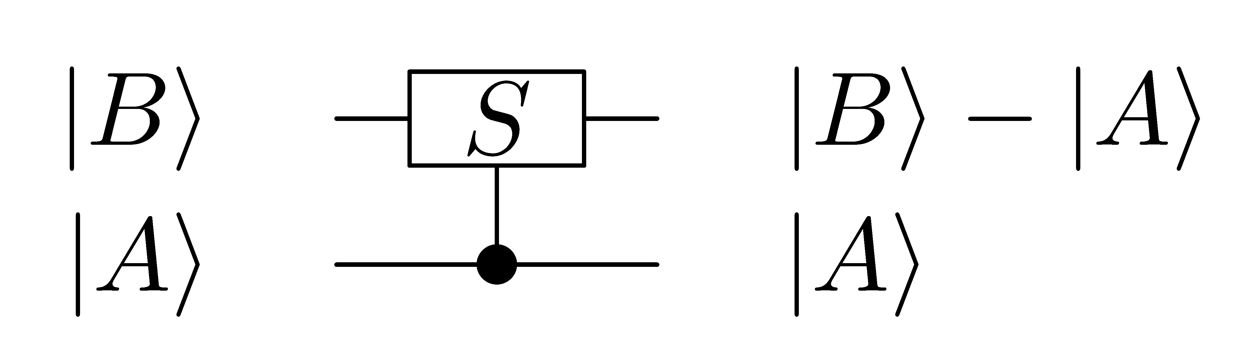
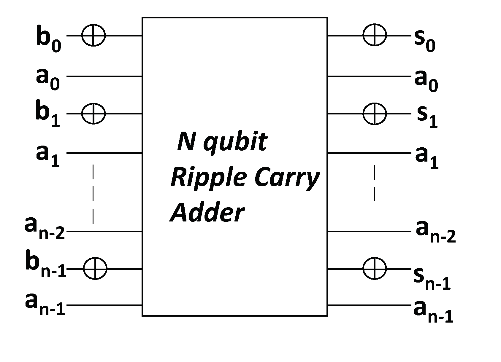
Fig.LABEL:Block_dia_of_subtractor shows the symbol and brief working of the quantum subtractor circuitry. The subtractor circuitry takes two n qubit inputs and . The input is regenerated at the output. The n-qubit output has the result of the subtraction of and , i.e., . Fig.2 shows the circuit design of N qubit subtractor based on N qubit quantum ripple carry adder. As shown in Fig.2, a quantum ripple carry adder is required to develop a quantum subtractor circuitry. Several examples of quantum ripple carry adder are proposed in the existing literature.[10] [11] [3] [12]. We compared these quantum ripple carry adder circuitries in terms of T-count and ancillary qubits. The comparison results have shown that the quantum ripple carry adder architecture proposed in [3] is superior to the other quantum ripple carry adder circuitries. Hence we used this quantum ripple carry adder for developing the quantum subtractor circuitry. The approach that is followed for developing the quantum subtractor circuitry is = . Both the inputs are passed through the quantum ripple carry adder. The input qubits are complemented at the start and at the end. The qubits are just passed through the quantum ripple carry adder.
2.2 Design of N qubit Quantum Conditional Addition operation Module
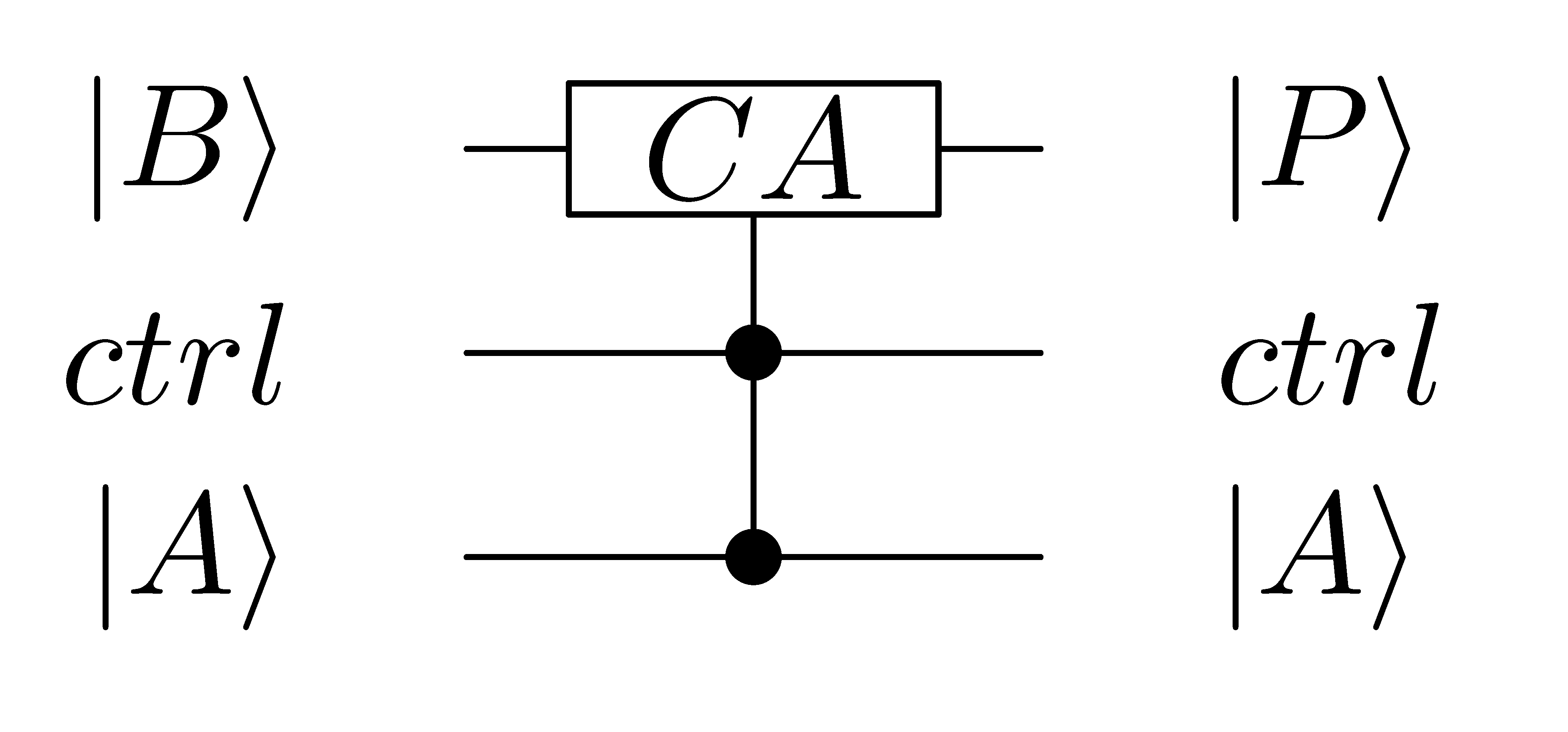
Fig.3 shows the graphic symbol of the quantum conditional ADD operation circuit. The quantum controlled ADD operation circuitry operates as: (i) when the input labeled is high (refer Fig.3), the circuit output is , (ii) when the input is low, the circuit output is .
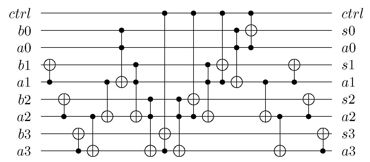
The complete working circuit of quantum conditional ADD operation circuitry is shown in Fig.4 for 4 qubit operands. The quantum conditional ADD circuit uses a modified version of the ripple carry adder proposed in [3]. We were able to remove the qubit that performs the carry out for the adder in [3] as we do not need carry out in the computation circuit of quantum conditional ADD. The addition architecture in [3] uses Peres gates to perform the addition. The Peres gate can be decomposed into a Feynman and a Toffoli gate. By replacing the Feynman gates with 3 input Toffoli gates, we are able to use the control line () to perform addition or no operation. Although, Fig.4 is just shown for 4 qubit operands, it can easily be extended to any operands sizes.
3 Proposed Design for Quantum Restoring Integer Division circuitry
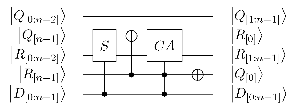
Fig.5 shows the proposed quantum circuit of restoring division for 1 iteration. We now elaborate on how information moves through the circuit.
Step 1. The holds the divisor, initialised to zero, and holds the dividend.
Step 2. We consider, and , as one combined register. This allows us to not use a left shifting circuit thereby saving quantum resources.
Step 3. The combined register mentioned above in Step 2, and are given as inputs to the quantum subtractor circuitry. Register emerges unchanged. The combined register now holds the result of subtraction of and registers. Let us call this result as .
Step 4. Qubits and are supplied to a CNOT gate. is the control qubit and the is the target qubit. The target now holds the value of because is always zero throughout the computation.
Step 5. The computed in Step 4 now becomes the control qubit to the conditional ADD circuit. and are the two qubit inputs to the conditional ADD operation circuit. The outputs of conditional ADD operation are collected. is complemented.
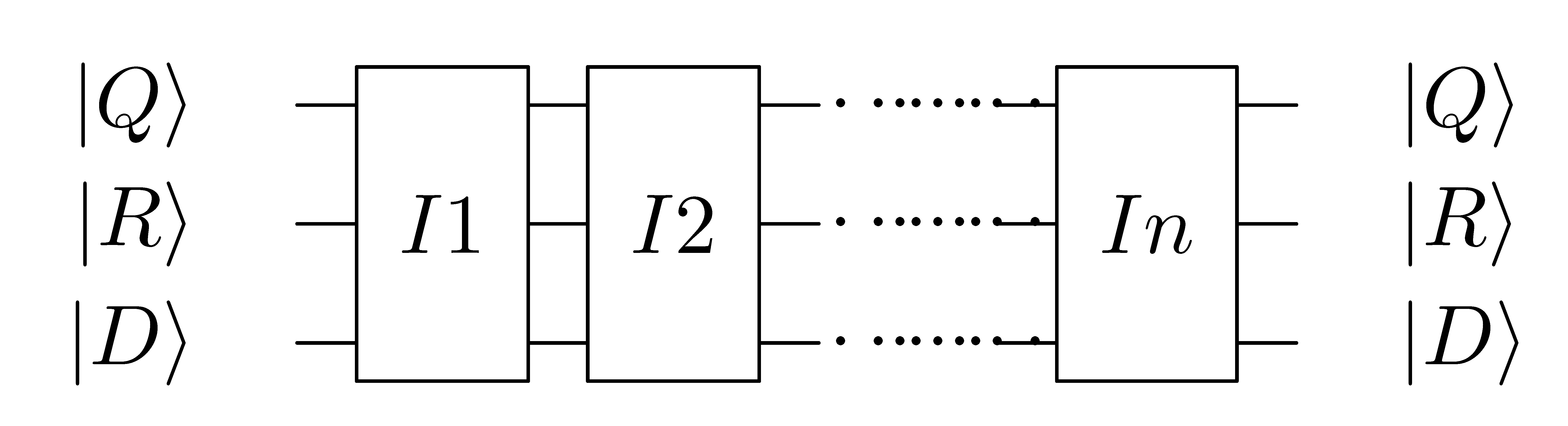
Step 6. All the above operations constitute the first iteration. From the Algorithm in Table 1, we can see that the whole circuit is iterated times. Hence, the circuit in Fig. 5 is also iterated times. This is done by using the outputs of first iteration will be used as inputs for the next iteration.
Step 7. This process continues for iterations. In Fig. 6, represents the first iteration. represents second iteration and represents iteration. The steps 1 through 6 have to go through each iteration till it reaches iterations. This process continues for iterations.
Step 8. At the end of iterations, we have Quotient in , remainder in and the divisor is retained. The dividend is not stored in our implementation.
The resources used in the design of the proposed quantum restoring integer division circuitry is presented in Table 2. As shown in Table 2, the proposed design will require ancillary qubits during initialization of remainder register. The T-count required by the design is given by summing the cost of subtractor and conditional ADD operation quantum circuitry at each stage. T-count of the proposed quantum restoring integer division circuitry is .
4 Comparison and Conclusion
We compared our proposed quantum restoring divider circuitry with the existing design in [2]. We compare the ancillaries and T-count. The quantum division circuit in [2] uses controlled phase shift gates. It is known that realising controlled phase gates other than the controlled T and phase gates with Clifford+T gates cannot be done exactly [1]. To calculate the T-counts for [2] we use T-counts from approximate phase gate implementations reported in [1]. The implementations with the poorest accuracy were used. This is because the T-count increases significantly as a function of accuracy. Comparison of resource estimation between proposed quantum circuitry of integer division and the existing quantum circuitry of integer division in [2] is shown in Table 3. T-count of the existing quantum circuitry of integer division in [2] is calculated for 3, 4 and 5 qubits and extrapolated for qubits. The proposed quantum circuitry of integer division has an improvement ratio of 50% in terms of ancillary qubits, and 91% in terms of T-count.
We presented the general behavioral model of restoring division algorithm for quantum circuits. A resource efficient design of the quantum circuitry of integer division is presented by optimizing the quantum circuits modules required by the design, and knitting them together efficiently. It is observed that non-restoring division algorithm can be an attractive choice to design quantum integer division circuit when minimizing the number of qubits is of primary concern. The proposed designs can be integrated in a larger data path subsystem designs to provide resource efficient implementation of quantum algorithms.
| Designs | Ancillaries | T-count |
|---|---|---|
| Subtractor | 0 | |
| conditional ADDER | 0 | |
| Initial Ancilla qubits | 0 | |
| Total cost |
| Designs | Ancillaries | T-count |
|---|---|---|
| existing design [2] | ||
| proposed design | ||
| Improvement ratio |
References
- [1] Kliuchnikov, V., Maslov, D. and Mosca, M., 2012. Fast and efficient exact synthesis of single qubit unitaries generated by Clifford and T gates. arXiv preprint arXiv:1206.5236.
- [2] Khosropour, A., Aghababa, H. and Forouzandeh, B., 2011, April. Quantum Division Circuit Based on Restoring Division Algorithm. In 2011 Eighth International Conference on Information Technology: New Generations.
- [3] Thapliyal, H. and Ranganathan, N., 2013. Design of efficient reversible logic-based binary and BCD adder circuits. ACM Journal on Emerging Technologies in Computing Systems (JETC), 9(3), p.17.
- [4] Amy, M., Maslov, D., Mosca, M. and Roetteler, M., 2013. A meet-in-the-middle algorithm for fast synthesis of depth-optimal quantum circuits. IEEE Transactions on Computer-Aided Design of Integrated Circuits and Systems, 32(6), pp.818-830.
- [5] Li, J., Peng, X., Du, J. and Suter, D., 2012. An efficient exact quantum algorithm for the integer square-free decomposition problem. Scientific reports, 2, p.260.
- [6] Miller, D.M., Soeken, M. and Drechsler, R., 2014, July. Mapping NCV circuits to optimized Clifford+ T circuits. In International Conference on Reversible Computation (pp. 163-175). Springer International Publishing.
- [7] Nielsen, M.A. and Chuang, I.L., 2010. Quantum computation and quantum information. Cambridge university press.
- [8] Pavlidis, A. and Gizopoulos, D., 2014. Fast quantum modular exponentiation architecture for Shor’s factoring algorithm. Quantum Information & Computation, 14(7 & 8), pp.649-682.
- [9] Yan, S.Y., 2013. Quantum attacks on public-key cryptosystems. Springer US.
- [10] Thapliyal, H., 2016. Mapping of Subtractor and Adder-Subtractor Circuits on Reversible Quantum Gates. In Transactions on Computational Science XXVII (pp. 10-34). Springer Berlin Heidelberg.
- [11] Cuccaro, S.A., Draper, T.G., Kutin, S.A. and Moulton, D.P., 2004. A new quantum ripple-carry addition circuit. arXiv preprint quant-ph/0410184.
- [12] Takahashi, Y. and Kunihiro, N., 2005. A linear-size quantum circuit for addition with no ancillary qubits. Quantum Information & Computation, 5(6), pp.440-448.
- [13] Thapliyal, H., Jayashree, H.V., Nagamani, A.N. and Arabnia, H.R., 2013. Progress in reversible processor design: a novel methodology for reversible carry look-ahead adder. In Transactions on Computational Science XVII (pp. 73-97). Springer Berlin Heidelberg.