Time-multiplexed amplification in a hybrid-less and coil-less Josephson parametric converter
Abstract
Josephson parametric converters (JPCs) are superconducting devices capable of performing nondegenerate, three-wave mixing in the microwave domain without losses. One drawback limiting their use in scalable quantum architectures is the large footprint of the auxiliary circuit needed for their operation, in particular, the use of off-chip, bulky, broadband hybrids and magnetic coils. Here, we realize a JPC which eliminates the need for these bulky components. The pump drive and flux bias are applied in the new device through an on-chip, lossless, three-port power divider and on-chip flux line, respectively. We show that the new design considerably simplifies the circuit and reduces the footprint of the device while maintaining a comparable performance to state-of-the-art JPCs. Furthermore, we exploit the tunable bandwidth property of the JPC and the added capability of applying alternating currents to the flux line in order to switch the resonance frequencies of the device, hence demonstrating time-multiplexed amplification of microwave tones that are separated by more than the dynamical bandwidth of the amplifier. Such a measurement technique can potentially serve to perform time-multiplexed, high-fidelity readout of superconducting qubits.
The Josephson parametric converter (JPC) is a valuable resource in the measurement and processing of quantum information carried by microwave signals JPCnaturePhys ; JPCnature ; JPCreview . It is used to perform high-fidelity, quantum nondemolition measurement of superconducting qubits JPCparity , track their quantum trajectories in realtime QubitJPC ; FluxoniumJumps , enable feedback FeedbackJPC , transduce quantum information via noiseless frequency conversion Conv ; QuantumNode , and generate two-mode squeezed states of the microwave field TwoModeSqueezing . JPCs also have the potential of serving as remote entanglers RemoteEntangler in distributed quantum networks.
However, despite the many useful applications of the JPC, state-of-the-art JPCs Jamp ; JPCreview ; CompactMixer suffer from three main limitations that hinder their use in scalable quantum architectures, i.e., narrow dynamical bandwidth on the order of at dB of gain, low saturation input power on the order of a few microwave photons per inverse dynamical bandwidth, both of which do not enable the readout of more than one qubit per JPC, and lastly the large footprint of the auxiliary drive and bias circuit needed for the operation of the device.
Here, we report on a new design and device which significantly simplifies the circuit and reduces the footprint of the JPC without degrading its performance. The new design is expected to not only promote scalability, but also to make it possible to realize quantum-limited directional amplifiers and noiseless circulators (as have been featured in recent works NoiselessCirc ; DircJPC ; JDA ; ReconfJJCircAmpl ). Furthermore, we demonstrate using the new device, a time-multiplexed amplification technique, which can ,in certain scenarios, extend the utility of the amplifier bandwidth.
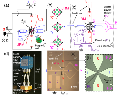
To recognize the important aspects of the new JPC and its additional functionality, it is crucial to first briefly review the standard JPC physics and circuit. The JPC is a quantum-limited, nondegenerate, three-wave mixing device with both its signal and idler modes spatially and spectrally separated JPCreview . In Fig. 1 (a) we show a circuit diagram of a state-of-the-art JPC. The main component of the JPC is the Josephson ring modulator (JRM) which functions as a nonlinear, dispersive mixing element. The JRM consists of four Josephson junctions (JJs) arranged in a Wheatstone bridge configuration (the outer loop). The JRM supports three microwave eigenmodes JPCnaturePhys whose excitation patterns are illustrated in Fig. 1 (b), namely, two differential modes denoted ‘X’ and ‘Y’ and one common denoted ‘Z’. The dc circulating current in the outer loop induced by an external magnetic flux threading the JRM facilitates the mixing operation between the three modes JPCnaturePhys . The other four large JJs inside the JRM serve as a linear shunt inductance for the outer JJs. The role of this inductive shunting is to lift the hysteretic response of the JRM versus flux and make the resonance frequencies of the JPC tunable Roch . In order to couple the JRM to microwave signals and enhance the mixing interaction, the JRM is embedded at the center of two orthogonal, half-wavelength microstrip transmission line resonators denoted signal (S) and idler (I) which are capacitively coupled to external feedlines that carry microwave signals into and out of the JPC and whose fundamental resonance modes couple strongly to the JRM modes ‘X’ and ‘Y’ respectively.
When operating the JPC as a quantum-limited parametric amplifier for S and I tones at frequencies and which lie within the dynamical bandwidth of the device, a non-resonant common drive denoted pump (P) (which couples to excitation ‘Z’) is applied to the device at frequency JPCnature ; Jamp . In order to address the S and I modes and apply the pump drive, both S and I tones are fed through the delta ports of two off-chip, broadband 180 degree hybrids, while the P is fed through the sigma port of one of the hybrids (the other sigma port is terminated by a Ohm cold load). As seen in the device photo shown in Fig. 1 (d), these hybrids (shown are Krytar Model 4060200) can be large in size. It is worth noting that at least one of the hybrids needs to be broadband in order to support either and or and which are in general separated by several gigahertz. Another disadvantage of this drive scheme is the insertion loss of the hybrids and the short matched coax cables connecting them to the JPC, which can be in the range 0.5-1.5 dB.
Our new JPC design aims to reduce the overall footprint and minimize the loss of off-chip components as schematically shown in Fig. 1 (c). In this scheme, we eliminate the broadband hybrids and short coaxes by implementing the S and I resonators in the form of open-ended half-wavelength transmission lines which are each capacitively coupled to a single feedline Roch . As for feeding the pump drive, we realize an on-chip, lossless, three-port power divider (PD) which is a variation on the T-junction power divider Pozar , that couples capacitively and symmetrically to two opposite nodes of the JRM (see supplementary material for another method of injecting the pump drive which yields similar results). In our case, the two arms of the PD couple to the top and bottom nodes as seen in Fig. 1 (e), (f). In designing the PD, three main considerations are taken into account, 1) keeping the two arms of the PD symmetrical, so that the injected pump is split evenly and in-phase between the two arms and, consequently inducing the desired ‘Z’ excitation of the JRM, 2) capacitively coupling the two arms of the PD as close as possible to the JRM, located at an rf-voltage node of the S and I modes, in order to reduce power leakage through the PD, and to the same end 3) keeping the two arms of the PD as far as possible from either resonator.
In addition, we implement an on-chip flux line (FL) [see Fig. 1(c), (e), (f)], with a mutual inductance to the JRM of about p. The FL allows us to flux bias the JRM without using external magnetic coils attached to the JPC package (see Fig. 1(d)). In addition to reducing the footprint of the JPC bias circuit, the FL has the advantage of supporting ac-currents/voltages and not only dc. Such capability can enable fast control of the amplifier gain and frequency as we show below. We have also incorporated into each side of the FL a basic low-pass, filtering element Pozar with a designed cutoff frequency around aimed at reducing power leakage from the S and I resonators through the FL (see Fig. 1 (e)).
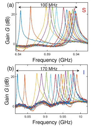
In Fig. 2 (a) and (b), we exhibit a tunable bandwidth measurement of the new device in which we measure the power gain on the S and I ports respectively, for various flux bias points. In this measurement, the pump is fed through the PD while the flux bias points are set via a dc current applied to the FL. Additional figures of merit of the device such as, gain, bandwidth, added noise, and maximum input power are included in the supplementary material and exhibit comparable performance to state-of-the-art JPCs.
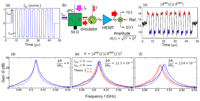
In the measurements of Fig. 3, we take advantage of the tunable bandwidth property of the JPC and the added capability of applying time varying currents to the FL in order to demonstrate time-multiplexed amplification between two adjacent signal frequencies which are separated by more than the dynamical bandwidth of the JPC. Such fast frequency switching can be used for example to time-multiplex the readout of two qubit-cavity systems, whose readout frequencies are adjacent but do not lie within the dynamical bandwidth of the amplifier.
To demonstrate time-multiplexed amplification, we set the JPC working point to dB of gain at and measure the JPC response in the time domain while applying current square pulses of duration to the FL with alternating sign (Fig. 3 (a)). In this measurement, the relation n ensures that the JPC reaches steady state during each pulse. In Fig. 3 (b), we show the main components of the setup used in measuring the device response for varying input probe frequency . By separately averaging the steady-state, time-domain output signal illustrated in Fig. 3 (c) for the positive and negative current pulses over runs, we obtain two amplitudes for each drawn using red and blue lines respectively. In Fig. 3 (d)-(f), we show the constructed two gain curves of the JPC corresponding to the positive (red) and negative (blue) current pulses measured for different current amplitudes (which induce different flux variation in the JRM). As expected, the two solid red and blue gain curves vary with the applied current amplitude. In the case of zero-amplitude current pulses, the gain curves overlap (Fig. 3 (d)). As the current amplitude is increased, the center frequencies of the gain curves deviate from each other (Fig. 3 (e)) and, consequently, the curves become distinguishable. By further increasing the applied current pulse amplitude, the two gain curves of dynamical bandwidth of become separated by while attaining power gain of dB (Fig. 3 (f)).
It is worth noting that for a fixed pump frequency , such as in our case, the maximum frequency separation between the gain curves that can be achieved using this technique without significantly degrading the gain (e.g., below dB), is in essence bounded by the smaller bandwidth of the two resonators JPCreview ; Jamp . This is because both resonance frequencies of the S and I shift in the same direction in response to the applied current pulse, while the amplification condition requires that the sum of the amplified S and I frequencies (residing within the respective bandwidths) stay equal to . Consequently, when the shifts in the resonance frequencies become comparable to the bandwidths of the resonators, the amplification condition, set for the fixed-flux case, becomes difficult to satisfy, which in turn leads to a decrease in the gain.
Another important figure related to time-multiplexed readout of quantum systems is the lower bound on , which is mainly limited by the measurement time needed to obtain a desired readout fidelity. This figure sets an upper bound on the rate at which a time-multiplexed readout can be performed. In the case of qubit-cavity systems, it is quite feasible to jointly optimize their parameters and the JPC’s to yield high readout fidelity with fast pulses ns QubitJPC ; FeedbackJPC .
In conclusion, we have realized and measured a JPC device which does not require the use of off-chip, bulky, broadband hybrids and external magnetic coils for its operation. In the new JPC circuit, the pump drive is fed through an on-chip, three-port power divider capacitively coupled to the JRM, and the flux bias is applied through an on-chip flux line. By eliminating the need for microwave hybrids and magnetic coils, we significantly reduce the device footprint without degrading its performance or adding complexity to the fabrication process. In addition, we have utilized the on-chip flux line to demonstrate time-multiplexed amplification of microwave tones that are separated by more than the dynamical bandwidth of the JPC by varying the magnetic flux threading the JRM using fast current pulses. Such a measurement technique can be potentially employed in the readout of pairs of qubit-resonator systems coupled to the same JPC. Furthermore, the new simplified JPC circuit, in which the pump, signal, and idler have separate physical ports, opens the door for the realization of broadband JPCs using impedance engineering techniques StrongEnvCoupling ; JPAimpedanceEng , and also useful quantum devices such as on-chip circulators and Josephson directional amplifiers DircJPC ; JDA .
Acknowledgements.
We thank Firat Solgun for fruitful discussions, James Rozen and John Rohrs for helpful technical support, Brian Vlastakis, Srikanth Srinivasan, and William Shanks for valuable programing and software assistance, and Christian Baks for the design and supply of PCBs used in mounting the JPC chips.References
- (1) N. Bergeal, R. Vijay, V.E. Manucharyan, I. Siddiqi, R. Schoelkopf, S. Girvin, and M. Devoret, Nat. Phys. 6, 296 (2010).
- (2) N. Bergeal, F. Schackert, M. Metcalfe, R. Vijay, V. Manucharyan, L. Frunzio, D. Prober, R. Schoelkopf, S. Girvin, and M. Devoret, Nature 465, 64 (2010).
- (3) B. Abdo, A. Kamal, M. H. Devoret, Phys. Rev. B 87, 014508 (2013).
- (4) L. Sun, A. Petrenko, Z. Leghtas, B. Vlastakis, G. Kirchmair, K. M. Sliwa, A. Narla, M. Hatridge, S. Shankar, J. Blumoff, L. Frunzio, M. Mirrahimi, M. Devoret, and R. Schoelkopf, Nature 511, 444 (2014).
- (5) M. Hatridge, S. Shankar, M. Mirrahimi, F. Schackert, K. Geerlings, T. Brecht, K. M. Sliwa, B. Abdo, L. Frunzio, S. Girvin, R. Schoelkopf, and M. Devoret, Science 339, 178 (2013).
- (6) U. Vool, I. Pop, K. Sliwa, B. Abdo, C. Wang, T. Brecht, Y. Y. Gao, S. Shankar, M. Hatridge, G. Catelani, M. Mirrahimi, L. Frunzio, R. Schoelkopf, L. Glazman, and M. Devoret, Phys. Rev. Lett. 113, 247001 (2014).
- (7) N. Ofek, A. Petrenko, R. Heeres, P. Reinhold, Z. Leghtas, B. Vlastakis, Y. Liu, L. Frunzio, S. Girvin, L. Jiang, M. Mirrahimi, M. Devoret, R. Schoelkopf, doi:10.1038/nature18949.
- (8) B. Abdo, K. Sliwa, F. Schackert, N. Bergeal, M. Hatridge, L. Frunzio, A. D. Stone, and M. Devoret, Phys. Rev. Lett. 110, 173902 (2013).
- (9) E. Flurin, N. Roch, J. D. Pillet, F. Mallet, and B. Huard, Phys. Rev. Lett. 114, 090503 (2015).
- (10) E. Flurin, N. Roch, F. Mallet, M. Devoret, and B. Huard, Phys. Rev. Lett. 109, 183901 (2012).
- (11) M. Silveri, E. Zalys-Geller, M. Hatridge, Z. Leghtas, M. Devoret, S. Girvin, arXiv:1507.00732v1 (2015).
- (12) B. Abdo, F. Schackert, M. Hatridge, C. Rigetti, and M. Devoret, Appl. Phys. Lett. 99, 162506 (2011).
- (13) J.-D. Pillet, E. Flurin, F. Mallet, and B. Huard, Appl. Phys. Lett. 106, 222603 (2015).
- (14) A. Kamal, J. Clarke, and M. Devoret, Nat. Phys. 7, 311 (2011).
- (15) B. Abdo, K. Sliwa, L. Frunzio, and M. H. Devoret, Phys. Rev. X 3, 031001 (2013).
- (16) B. Abdo, K. Sliwa, S. Shankar, M. Hatridge, L. Frunzio, R. Schoelkopf, and M. Devoret, Phys. Rev. Lett. 112, 167701 (2014).
- (17) K. Sliwa, M. Hatridge, A. Narla, S. Shankar, L. Frunzio, R. Schoelkopf, and M. Devoret, Phys. Rev. X 5, 041020 (2015).
- (18) D. M. Pozar, Microwave Engineering, 3rd edition, (Wiley, Hoboken, NJ, 2005).
- (19) N. Roch, E. Flurin, F. Nguyen, P. Morfin, P. Campagne-Ibarcq, M. Devoret and B. Huard, Phys. Rev. Lett. 108, 147701 (2012).
- (20) J. Mutus, T. White, R. Barends, Y. Chen, Z. Chen, B. Chiaro, A. Dunsworth, E. Jeffrey, J. Kelly, A. Megrant, C. Neill, P. O’Malley, P. Roushan, D. Sank, A. Vainsencher, J. Wenner, K. Sundqvist, A. Cleland, J. Martinis, Appl. Phys. Lett. 104, 263513 (2014).
- (21) T. Roy, S. Kundu, M. Chand, A. Vadiraj, A. Ranadive, N. Nehra, M. Patankar, J. Aumentado, A. Clerk, and R. Vijay, Appl. Phys. Lett. 107, 262601 (2015).