Continuous generation of delayed light
Abstract
We use a Raman four-wave mixing process to read-out light from atomic coherence which is continuously written. The light is continuously generated after an effective delay, allowing the atomic coherence to evolve during the process. Contrary to slow-light delay, which depends on the medium optical depth, here the generation delay is determined solely by the intensive properties of the system, approaching the atomic coherence lifetime at the weak driving limit. The generated light is background free. We experimentally probe these properties utilizing spatial diffusion as an ’internal clock’ for the atomic evolution time. Continuous generation of light with a long intrinsic delay can replace discrete write-read procedures when the atomic evolution is the subject of interest.
pacs:
42.50.Gy-
June 2017
Keywords: EIT, slow light, Raman four-wave mixing, coherent diffusion
1 Introduction
The interplay between optical fields and long-lived coherences in multi-level atoms provides a rich playground for fundamental and practical research. The basic process involves two fields and three levels in a or ladder configuration, giving rise to Raman transitions, electromagnetically-induced transparency (EIT) [1], and coherent population trapping (CPT) [2], and leading to implementations of frequency standards [3], magnetometers [4], quantum memories and sources [5, 6, 7], and quantum nonlinear optics [8, 9, 10, 11]. In applications relying on EIT and CPT, the contrast of the transmitted signal and the group delay in the medium play a crucial role, determining the metrological accuracy or the process fidelity.
From the basic tools of EIT and CPT, one can construct composite schemes, involving 3 or 4 fields and 4 levels [12]. Various 4-wave mixing processes have been investigated, particularly for quantum optics, such as generation of entangled and squeezed light [13, 14] and single-photon sources [15]. Here, we study a distinct 4-wave mixing regime, where a signal field is generated with near unity contrast after a finite delay time. As opposed to standard slow light via EIT, here the signal delay is determined only by the linewidth of the Raman transition and is insensitive to extensive variables (e.g., number of atoms, population distribution, optical depth). The light is continuously generated from a Raman coherence that has evolved for a finite duration.
Let us briefly review the various existing schemes involving two strong control fields and two weak probe fields. Parametric gain, via the conversion of two control photons to two probe photons, occurs in a so-called closed double- (D) configuration and leads to entangled (twin) photon generation [14, 16]. Parametric conversion, where the two probe fields are effectively coupled, and the total number of probe photons is conserved, occurs in an open D [17] and a double-V (DV) [18] configurations. Our configuration is a DV, which is the least studied [18, 19, 20].
In an open D, the control fields form a system with two ground-states and one excited state. This leads to CPT with a Raman coherence that is generally a spatial grating, thus the name ‘electromagnetically induced grating’ [21]. Due to motion of the atoms through the grating, the process is sensitive to the wave-vector mismatch between the two control fields. The probe fields form a second -system with a different excited state and experience the induced grating [22, 23]. For a single incoming probe, its diffraction by the grating generates the second probe [24], providing a Raman-spectroscopy signal with near-unity contrast [25]. However the probe fields are not substantially slowed, as the control fields alone dictate the Raman detuning.
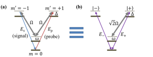
In a DV configuration, depicted in Fig. 1(a), the control fields couple one ground state to two excited states. No ground-state coherence is formed without the probe fields, and thus no grating is created. Similarly to the open D, one incoming probe field generates the other; However, in the DV, the process is sensitive to the Raman detuning between the probe and the control and insensitive to that between the controls. The scheme we study utilizes both these properties.
Note that the DV configuration is equivalent to the double ladder configuration [26] — where control (probe) fields drive the upper (lower) transitions — but the Raman coherence is usually longer lived in the DV. The efficiency of 4-wave mixing in both configurations has received considerable attention [26, 27, 19]. Here we focus on the temporal properties of the process. Contrary to a recent work [28], we study the regime of very long intrinsic delay times, manifesting the continuous read-out of light.
2 Experiment
We use 87Rb vapor and 10 Torr of N2 buffer gas in a cell of length 7.5 cm at C. The DV system [Fig. 1(a)] comprises the states of the ground 5S1/2 level and the states of the excited 5P1/2 level of the D1 transition. We define the one-photon detuning from and experimentally vary over a 1 GHz range, such that generally both and participate in the process. A 50-mG longitudinal magnetic field guarantees that the spectator ground states are far from the Raman resonance conditions. The light from an amplified 795-nm diode laser is split into one probe and two control beams. We shift the probe frequency by the hyperfine splitting 6.8 GHz using optical modulators, followed by an etalon filter. These are also used to scan the two-photon detuning and temporally shape the probe pulses. The probe is aligned with one control beam, while the second control beam is sent at a mechanically-controlled angular deviation mrad. All beams are collimated to a diameter 8 mm and spatially overlap when crossing the vapor cell. After the cell, the probe and signal angularly separate, and we filter them from the control light using etalons. The resonant optical depth for the probe and signal increases from at a control power mW to at mW.
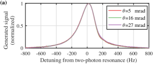
The robustness of the scheme is demonstrated by the generation spectra in Fig. 2(a). The lineshape does not depend on the relative polarizations of the control beams or on the deviation angle between them (for ). This confirms that no spatial grating of the ground-state coherence is formed by the controls. In particular, the phase-matching conditions are equally fulfilled regardless of , since does not impact each of the two systems separately. Note that this property is exploited in counter-propagating DV configurations () [29, 30].
The measurements in Fig. 2(a) are done at MHz, where the transmission spectrum has a characteristic Fano-like lineshape. However, the generation lineshape remains a Lorentzian regardless of , further manifesting the robustness of the lineshape.
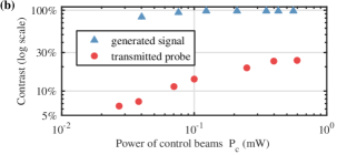
Figure 2(b) presents a comparison between the contrasts of the generation and transmission spectra. While the contrast of the transmitted probe vanishes for low control power, the signal is generated with no background and thus with near unity contrast regardless of the control parameters.
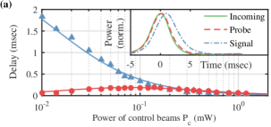
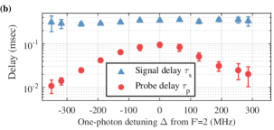
We send probe pulses, shown in Fig. 3 (inset), to measure the delay of the transmitted probe and the delay of the generated signal . As summarized in Fig. 3(a), vanishes when the control power is lowered, whereas monotonically increases. This striking feature of the generation process stems from its near-perfect contrast [Fig. 2(b)], as the group delay is proportional to the ratio between the contrast and width of the spectral line [31]. While this ratio renders a well-known tradeoff in the probe channel (both contrast and width increase with control power), it is clearly maximized for weak control in the signal channel. Fig. 3(b) shows that for low control power, is insensitive to the one-photon detuning . In contrast, decreases at large detuning .
As we will show, approaches the lifetime of the Raman coherence (measured 3 ms in our system) for low control power. Indeed this intuitively should be the upper limit: The probe and the co-propagating control act to ‘write’ the ground-state coherence, having a lifetime , and the second control ‘reads’ it. This implies that the signal is continuously generated from atomic Raman coherence that has evolved for a duration .
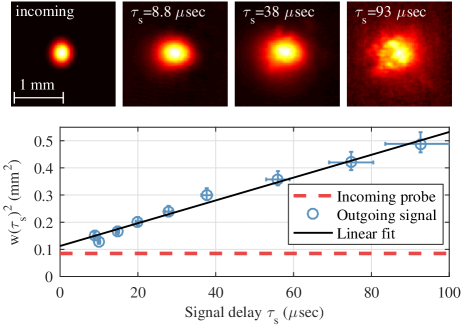
To validate this picture, we measure the spatial evolution in the planes transverse to the propagation direction. The transverse evolution in the paraxial regime are largely separable from the longitudinal evolution [32], providing an effective internal clock for the continuous generation process. In standard ’light storage’ procedures, the ground-state coherence of the diffusing atoms undergoes spatial diffusion [33, 34]. Consequently for our process, the transverse distance traveled by the diffusing atoms from which the signal light is read quantifies the effective atomic evolution time.
We perform experiments with a narrow Gaussian probe beam and image the generated signal onto a camera (Fig. 4). We vary the signal delay by altering the control power . The one-photon detuning is MHz; the small shift of the state due to the varying power of the off-resonant control is compensated for by fine tuning the probe frequency, thus maintaining the two-photon resonance. The Gaussian shape is imprinted on the atoms and expands due to atomic diffusion. Using the measured Gaussian width , we fit [34] to extract the diffusion coefficient mm2/s. This matches the calculated value [35, 36], which we also measure in independent storage experiments. We conclude that the atomic coherence evolves for the duration before generating the signal.
3 Theoretical model
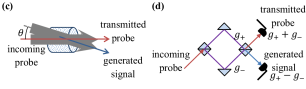
Full Maxwell-Bloch models of DV systems are known and have been solved for various scenarios [18, 20, 26, 27, 28]. Here to construct a simple model, we notice that the control beams couple the ground state to a specific superposition of the two excited states, denoted as in Fig. 1(c). Thus instead of the bare probe and signal fields, it is convenient to use the normal modes and , which respectively couple to and its orthogonal superposition . Here, the ’s denote the slowly varying field envelopes in space and time. Only experiences EIT (note the difference with the open D scheme, where neither of the normal modes experiences EIT [12]). The medium then acts as the effective Mach-Zehnder interferometer in Fig. 1(d), where the incoming probe decomposes into and upon entering the medium.
Instead of solving coupled propagation equations for the bare modes, we immediately express the normal modes at the medium exit as using the known linear susceptibility with and without EIT. The transmission amplitudes with and without EIT are, respectively, and [1], where
| (1) |
are complex Lorentzians associated with the one-photon and two-photon resonances, with and the corresponding decoherence rates. Both the power broadening term and the ratio of ‘active’ atoms (in the -system) to ‘spectator’ atoms depend on the Rabi frequency of the control beams (assumed equal). The real and imaginary parts of correspond respectively to line broadening and to light shift at . Note that the model, here presented for atoms at rest, can be generalized for a thermal medium predominantly by correcting and to account for the broadening of the one-photon spectrum [32].
For an incoming probe field , the transmitted probe is given by and the generated signal by . A signal is generated when , i.e. when due to EIT. We identify the limit of weak EIT with , which is oftentimes the case even in optically thick media: Limited control power and a desire to minimize power broadening restrict the induced transparency. Additionally, ‘spectator’ atoms residing in states outside the -system (here ) contribute to the absorption but are unaffected by EIT ().
The generation efficiency at the weak EIT limit is low, as can be calculated from
| (2) |
For the experimental conditions of Figs. 2 and 3(a), the measured efficiency at low control power is , agreeing with that estimated from the above expression ( and ). We shall assume that and vary only slightly with near the EIT resonance. This assumption holds for an EIT resonance much narrower than the optical resonance, as occurring in a hot vapor. The generation spectrum near resonance thus has the shape . Notably, it is Lorentzian regardless of as evident by Fig. 2(b), as opposed to the asymmetric (Fano-like) lineshape of the transmitted probe at large .
We now turn to explain the striking features of the generated signal observed in the temporal and spatial domains. The delay of the transmitted probe stems from a well-studied mechanism of slow light due to the large group index on EIT resonance. When , the group delay of the probe and signal can be calculated for the whole medium using (This expression is easily understood for a purely dispersive medium by replacing with to find ). From and Eq. (1), and assuming and negligible and , we find the group delay of the probe
| (3) |
at . For , all these parameters are real, and . The dependence of on the optical depth (and thus on the atomic density and the length of medium), as well as on the population ratio and on the control power (via ), is well-known for EIT slow-light [31].
With Eqs. (1) and (2), we find the group delay of the signal at
| (4) |
As opposed to standard ‘delay lines’, and in contrast to the probe delay, the signal delay is independent of any extensive parameter, such as the medium length, optical depth, or level population. It is also independent of the EIT contrast, remaining finite for weak control fields. For vanishing control , the probe delay vanishes , while the signal exhibits maximal delay as observed in Fig. 3(a).
For fitting in Fig. 3(a), we use , were the power broadening versus is calibrated from independent spectra measurements for a range of . The value (3 msec)-1 is found by linear extrapolation of to . is described by Eq. (3), depending additionally on . The optical depth and population distribution vary due to optical pumping, and thus depends on . We calibrate this dependence from measured spectra. The need to calibrate the optical pumping processes in standard slow-light applications exemplifies the intricate dependence of on various system parameters versus the ’naturalness’ of .
To describe spatially-structured fields, we work in Fourier space of the transverse planes, where the field envelopes of the probe and signal are functions of the transverse wave-vector . The Raman process depends on , since nonzero represents a wave-vector mismatch between the probe or signal and their corresponding control field. The -dependence of the process is a consequence of motional line broadening. The diffusion of Rb in the buffer gas across the Raman wavelengths () results in a broadening quadratic in due to the Dicke effect. To account for this, one only needs to generalize in Eq. (1) to a -dependent by replacing [32, 37]. In this description, we ignore paraxial diffraction, the mismatch due to the hyperfine splitting, and a small offset to (on order ) due to the angular deviation of the controls; all of these can easily be added to the model and are unimportant at our conditions.
It has been shown previously for slow light [38] that the quadratic broadening results in diffusion of the probe envelope for the duration of the group delay , under the conditions of resonant excitation () and confined spatial spectrum . Under these conditions,
| (5) |
Now for the signal field, we substitute into Eq. (2) and find . The ‘filter’ in -space leads to diffusion in real space for the duration . This solution agrees with the physical picture of light generation after an atomic evolution time . Figure 4 demonstrates the validity of this picture, even beyond the weak EIT condition (with ).
4 Conclusions
In conclusion, the continuous generation process facilitates studies of atomic evolution (internal or external) and interatomic interactions. The absence of background incident light in the outgoing signal offers reduced noise for metrology applications and higher purity for quantum-optics applications. One exciting prospect is to utilize the atomic evolution for generation of non-classical signal fields, particularly anti-bunched light. Generation of anti-bunched light due to interactions between Rydberg atoms was recently demonstrated in a discrete write-read procedure [39]. The same mechanisms, applied for the effective duration of the atomic evolution in our scheme, could provide a continuous source of single photons. Here the low generation efficiency does not limit the anti-bunching fidelity. Furthermore in contrast to continuous collinear configurations, such as Rydberg-EIT [40], the anti-bunching statistics in our scheme will not be limited by the optical depth. Our scheme is thus particularly suitable for media with low optical depth, e.g. in miniature hot-vapor cells.
Acknowledgments
We acknowledge financial support by the Israel Science Foundation and ICORE, the Laboratory in Memory of Leon and Blacky Broder, and the Sir Charles Clore research prize.
References
References
- [1] Fleischhauer M, Imamoglu A and Marangos J P 2005 Rev. Mod. Phys. 77 633
- [2] Arimondo E 1996 Progress in optics 35 257–354
- [3] Knappe S, Shah V, Schwindt P D D, Hollberg L, Kitching J, Liew L A and Moreland J 2004 Appl. Phys. Lett. 85 1460–1462
- [4] Budker D and Romalis M 2007 Nature Physics 3 227–234
- [5] Eisaman M D, Andre A, Massou F, ans A S Zibrov M F and Lukin M D 2005 Nature (London) 438 837–841
- [6] Zhao R, Dudin Y O, Jenkins S D, Campbell C J, Matsukevich D N, Kennedy T A B and Kuzmich A 2008 Nature Physics 5 100–104
- [7] Michelberger P S, Champion T F M, Sprague M R, Kaczmarek K T, Barbieri M, Jin X M, England D G, Kolthammer W S, Saunders D J, Nunn J and Walmsley I A 2015 New Journal of Physics 17 043006 URL http://stacks.iop.org/1367-2630/17/i=4/a=043006
- [8] Firstenberg O, Adams C S and Hofferberth S 2016 Journal of Physics B: Atomic, Molecular and Optical Physics 49 152003 URL http://stacks.iop.org/0953-4075/49/i=15/a=152003
- [9] Firstenberg O, Peyronel T, Liang Q Y, Gorshkov A V, Lukin M D and Vuletic V 2013 Nature (London) 502 71–75
- [10] Gorniaczyk H, Tresp C, Schmidt J, Fedder H and Hofferberth S 2014 Phys. Rev. Lett. 113(5) 053601
- [11] Tiarks D, Schmidt S, Rempe G and Dürr S 2016 Science Advances 2 e1600036
- [12] Lukin M, Hemmer P and Scully M 2000 Advances In Atomic, Molecular, and Optical Physics 42 347 – 386 ISSN 1049-250X URL http://www.sciencedirect.com/science/article/pii/S1049250X08601901
- [13] Marino A M, Pooser R C, Boyer V and Lett P D 2009 Nature (London) 457 859–862
- [14] Hammerer K, Sørensen A S and Polzik E S 2010 Rev. Mod. Phys. 82 1041–1093
- [15] Matsukevich D N, Chanelière T, Jenkins S D, Lan S Y, Kennedy T A B and Kuzmich A 2006 Phys. Rev. Lett. 97(1) 013601
- [16] Glorieux Q, Dubessy R, Guibal S, Guidoni L, Likforman J P, Coudreau T and Arimondo E 2010 Phys. Rev. A 82 033819
- [17] Kocharovskaya O and Mandel P 1990 Phys. Rev. A 42(1) 523–535 URL http://link.aps.org/doi/10.1103/PhysRevA.42.523
- [18] Cerboneschi E and Arimondo E 1996 Optics Communications 127 55 – 61 ISSN 0030-4018 URL http://www.sciencedirect.com/science/article/pii/0030401896000582
- [19] Wang G, Cen L, Qu Y, Xue Y, Wu J H and Gao J Y 2011 Opt. Express 19 21614–21619 URL http://www.opticsexpress.org/abstract.cfm?URI=oe-19-22-21614
- [20] Kani A and Wanare H 2014 Opt. Express 22 15305–15314 URL http://www.opticsexpress.org/abstract.cfm?URI=oe-22-12-15305
- [21] Ling H Y, Li Y Q and Xiao M 1998 Physical Review A 57 1338
- [22] Cerboneschi E and Arimondo E 1995 Phys. Rev. A 52(3) R1823–R1826 URL http://link.aps.org/doi/10.1103/PhysRevA.52.R1823
- [23] Korsunsky E A and Kosachiov D V 1999 Phys. Rev. A 60(6) 4996–5009 URL http://link.aps.org/doi/10.1103/PhysRevA.60.4996
- [24] Hemmer P R, Katz D P, Donoghue J, Shahriar M S, Kumar P and Cronin-Golomb M 1995 Opt. Lett. 20 982–984 URL http://ol.osa.org/abstract.cfm?URI=ol-20-9-982
- [25] Shah V, Knappe S, Hollberg L and Kitching J 2007 Opt. Lett. 32 1244–1246 URL http://ol.osa.org/abstract.cfm?URI=ol-32-10-1244
- [26] Hsu P S, Patnaik A K and Welch G R 2008 Opt. Lett. 33 381–383 URL http://ol.osa.org/abstract.cfm?URI=ol-33-4-381
- [27] Becerra F E, Willis R T, Rolston S L and Orozco L A 2008 Phys. Rev. A 78(1) 013834 URL http://link.aps.org/doi/10.1103/PhysRevA.78.013834
- [28] Dong-Sheng D, Zhi-Yuan Z and Bao-Sen S 2013 Chinese Physics B 22 114203 URL http://stacks.iop.org/1674-1056/22/i=11/a=114203
- [29] Bajcsy M, Zibrov A S and Lukin M D 2003 Nature 426 638–641
- [30] Lin Y W, Liao W T, Peters T, Chou H C, Wang J S, Cho H W, Kuan P C and Ite A Y 2009 Physical review letters 102 213601
- [31] Klein M, Hohensee M, Xiao Y, Kalra R, Phillips D F and Walsworth R L 2009 Phys. Rev. A 79(5) 053833 URL http://link.aps.org/doi/10.1103/PhysRevA.79.053833
- [32] Firstenberg O, Shuker M, Pugatch R, Fredkin D R, Davidson N and Ron A 2008 Phys. Rev. A 77 043830
- [33] Shuker M, Firstenberg O, Pugatch R, Ron A and Davidson N 2008 Phys. Rev. Lett. 100 223601
- [34] Firstenberg O, London P, Yankelev D, Pugatch R, Shuker M and Davidson N 2010 Phys. Rev. Lett. 105 183602
- [35] Ishikawa K and Yabuzaki T 2000 Phys. Rev. A 62(6) 065401 URL http://link.aps.org/doi/10.1103/PhysRevA.62.065401
- [36] Ma J, Kishinevski A, Jau Y Y, Reuter C and Happer W 2009 Phys. Rev. A 79(4) 042905 URL http://link.aps.org/doi/10.1103/PhysRevA.79.042905
- [37] Firstenberg O, Shuker M, Ron A and Davidson N 2013 Rev. Mod. Phys. 85 941–960
- [38] Firstenberg O, London P, Shuker M, Ron A and Davidson N 2009 Nature Physics 5 665–668
- [39] Dudin Y O and Kuzmich A 2012 Science 336 887–889
- [40] Peyronel T, Firstenberg O, Liang Q Y, Hofferberth S, Gorshkov A V, Pohl T, Lukin M D and Vuletic V 2012 Nature (London) 488 57–60