Topological Drawings of Complete Bipartite Graphs
Abstract
Topological drawings are natural representations of graphs in the plane, where vertices are represented by points, and edges by curves connecting the points. Topological drawings of complete graphs and of complete bipartite graphs have been studied extensively in the context of crossing number problems. We consider a natural class of simple topological drawings of complete bipartite graphs, in which we require that one side of the vertex set bipartition lies on the outer boundary of the drawing.
We investigate the combinatorics of such drawings. For this purpose, we define combinatorial encodings of the drawings by enumerating the distinct drawings of subgraphs isomorphic to and , and investigate the constraints they must satisfy. We prove that a drawing of exists if and only if some simple local conditions are satisfied by the encodings. This directly yields a polynomial-time algorithm for deciding the existence of such a drawing given the encoding. We show the encoding is equivalent to specifying which pairs of edges cross, yielding a similar polynomial-time algorithm for the realizability of abstract topological graphs.
We also completely characterize and enumerate such drawings of in which the order of the edges around each vertex is the same for vertices on the same side of the bipartition. Finally, we investigate drawings of using straight lines and pseudolines, and consider the complexity of the corresponding realizability problems.
1 Introduction
We consider topological graph drawings, which are drawings of simple undirected graphs where vertices are represented by points in the plane, and edges are represented by simple curves that connect the corresponding points. We typically restrict those drawings to satisfy some natural nondegeneracy conditions. In particular, we consider simple drawings, in which every pair of edges intersect at most once. A common vertex counts as an intersection.
While being perhaps the most natural and the most used representations of graphs, simple drawings are far from being understood from the combinatorial point of view. A prominent illustration is the problem of identifying the minimum number of edge crossings in a simple topological drawing of [9, 3, 1] or of [22, 4], for which there are long standing conjectures.
In order to cope with the inherent complexity of the drawings, it is useful to consider combinatorial abstractions. Those abstractions are discrete structures encoding some features of a drawing. One such abstraction, introduced by Kratochvíl, Lubiw, and Nešetřil, is called abstract topological graphs (AT-graph) [11]. An AT-graph consists of a graph together with a set . A topological drawing is said to realize an AT-graph if the pairs of edges that cross are exactly those in . Another abstraction of a topological drawing is called the rotation system. The rotation system associates a circular permutation with every vertex , which in a realization must correspond to the order in which the neighbors of are connected to . Natural realizability problems are: given an AT-graph or a rotation system, is it realizable as a topological drawing? The realizability problem for AT-graphs is known to be NP-complete [12].
For simple topological drawings of complete graphs, the two abstractions are actually equivalent [18]. It is possible to reconstruct the set of crossing pairs of edges by looking at the rotation system, and vice-versa (up to reversal of all permutations). Kynčl recently proved the remarkable result that a complete AT-graph (an AT-graph for which the underlying graph is complete) can be realized as a simple topological drawing of if and only if all the AT-subgraphs on at most 6 vertices are realizable [13, 15]. This directly yields a polynomial-time algorithm for the realizability problem. While this provides a key insight on topological drawings of complete graphs, similar realizability problems already appear much more difficult when they involve complete bipartite graphs. In that case, knowing the rotation system is not sufficient for recontructing the intersecting pairs of edges.
We propose a fine-grained analysis of simple topological drawings of complete bipartite graphs. In order to make the analysis more tractable, we introduce a natural restriction on the drawings, by requiring that one side of the vertex set bipartition lies on a circle at infinity. This gives rise to meaningful, yet complex enough, combinatorial structures.
Definitions.
We wish to draw the complete bipartite graph in the plane in such a way that:
-
1.
vertices are represented by points,
-
2.
edges are continuous curves that connect those points, and do not contain any other vertices than their two endpoints
-
3.
no more than two edges intersect in one point,
-
4.
edges pairwise intersect at most once; in particular, edges incident to the same vertex intersect only at this vertex,
-
5.
the vertices of one side of the bipartition lie on the outer boundary of the drawing.
Properties 1–4 are the usual requirements for simple topological drawings also known as good drawings. As we will see, property 5 leads to drawings with interesting combinatorial structures. We will refer to drawings satisfying properties 1–5 as outer drawings. Since this is the only type of drawings we consider, we will use the single term drawing instead when the context is clear.
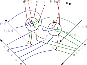
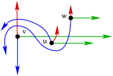
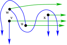
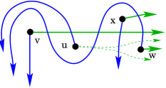
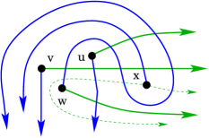
The set of vertices of a bipartite graph will be denoted by , where and are the two sides of the bipartition, with and . When we consider a given drawing, we will use the word “vertex” and “edge” to denote both the vertex or edge of the graph, and their representation as points and curves. Without loss of generality, we can assume that the outer vertices lie in clockwise order on the boundary of a disk that contains all the edges, or on the line at infinity. The vertices of are labeled . An example of such a drawing is given in Figure LABEL:fig:example-1.
14example-1Two outer drawings of . In both drawings the rotation system is .
The rotation system of the drawing is a sequence of permutations on elements associated with the vertices of in clockwise order. For each vertex of , its permutation encodes the (say) counterclockwise order in which the vertices of are connected to it. Due to our last constraint on the drawings, the rotations of the vertices of around each vertex of are fixed and identical, they reflect the clockwise order of on the boundary.
Unlike for complete graphs, the rotation system of an outer drawing of a complete bipartite graph does not completely determine which pairs of edges are intersecting. This is exemplified with the two drawings in Figure LABEL:fig:example-1.
Results.
The paper is organized as follows. In Section 2, we consider outer drawings with a uniform rotation system, in which the permutations of the vertices of are all equal to the identity. In this case, we can state a general structure theorem that allows us to completely characterize and count outer drawings of arbitrary bipartite graphs .
In Section 3, we consider outer drawings of with arbitrary rotation systems. We consider a natural combinatorial encoding of such drawings, and state two necessary consistency conditions involving triples and quadruples of points in . We show that these conditions are also sufficient, yielding a polynomial-time algorithm for checking consistency of a drawing.
We also observe that our encoding is equivalent to specifying which pairs of edges must intersect in the drawing, hence exactly encodes the corresponding AT-graph. Therefore we show as a corollary that we can decide the realizability of a given AT-graph with underlying graph isomorphic to in polynomial time.
In Section 4 and 5, we extend these results, first to outer drawings of , then to outer drawings of . We prove that simple consistency conditions on triples and quadruples are sufficient for drawings of , yielding again a polynomial-time algorithm for consistency checking.
In Section 6, we consider outer drawings with the additional property that the edges can be extended into a pseudoline arrangement, which we refer to as extendable drawings. We give a necessary and sufficient condition for the existence of an extendable outer drawing of a complete bipartite graph given the rotation system. We also touch upon the even more restricted problem of finding straight-line outer drawings with prescribed rotation systems.
2 Outer Drawings with uniform rotation system
We first consider the case where is arbitrary but the rotation system is uniform, that is, the permutation around each of the vertices is the same. Without loss of generality we assume that this permutation is the identity permutation on .
In a given outer drawing, each of the vertices of splits the plane into regions , where each is bounded by the edges from to and , with the understanding that . We denote by the th region defined by vertex and further on call these regions quadrants. We let , for and , whenever . This implies that , see Figure LABEL:fig:quadrants. Indeed if and , then edge has to intersect all the edges , while edge has to avoid until they meet in . It follows that none of the edges can intersect . This shows that .
30quadrantsHaving placed in the crossing pairs of edges and the order of crossings on each edge is prescribed. In particular . On the right a symmetric outer drawing of the pair.
Observation 1 (Symmetry).
For all , in uniform rotation systems:
For the case , we have exactly two types of pairs, that we will denote by and . The two types are illustrated on Figure LABEL:fig:pseudolines-1. Note that the two types can be distinguished by specifying which are the pairs of intersecting edges. The outer drawings of with uniform rotations can be viewed as colored pseudoline arrangements, where:
-
•
each pseudoline is split into two segments of distinct colors,
-
•
no crossing is monochromatic.
30pseudolines-1The two types of pairs for outer drawings of with uniform rotation systems.
This is illustrated on Figure LABEL:fig:pseudolines-2. The pseudoline of a vertex is denoted by . The left (red) and right (blue) parts of this pseudoline are denote by and . Now having means that lies above and lies above . While having means that lies below and lies below .
30pseudolines-2Drawing as a colored pseudoline arrangement. The type of each pair is given in the table on the right.
2.1 The triple rule
Lemma 2 (Triple rule).
For uniform rotation systems and three vertices with
Proof.
Case . If there is nothing to show since there are only two types. Without loss of generality, suppose that . This situation is illustrated in the left part of Figure LABEL:fig:triple-both. The pseudoline must cross on , otherwise we would have . Hence the point is on the right of this intersection. Pseudoline must cross on , and is left of this intersection. It follows that and cross on and , i.e., . \PsFigCap30triple-bothIllustrations for the case of Lemma 2 (left), and the case of Lemma 2 (right).
Case . For the general case assume that and . If there is nothing to show. Now suppose . From it follows that and are disjoint. Edges and only share the endpoint , hence has to be in the region delimited by and , see the right part of Figure LABEL:fig:triple-both. This region is contained in , whence . ∎
2.2 The quadruple rule
Lemma 3 (Quadruple rule).
For four vertices with :
if then .
Proof.
Case . Suppose, without loss of generality, that . Consider the pseudolines representing and with their crossing at . Coming from the left the edge has to avoid and therefore intersects . On the crossing with is left of the crossing with , see Figure LABEL:fig:quadruple. Symmetrically from the right the edge has to intersect and this intersection is left of . To reach the crossings with and edges and have to intersect, hence, .
30quadrupleIllustration for the case of Lemma 2.
Case . In the general case, we let , and consider the pseudoline arrangement defined by the two successive vertices and of defining the quadrants . Proving that , that is, that , can be done as above for on the drawing of induced by and . ∎
2.3 Decomposability and Counting
We can now state a general structure theorem for all outer drawings of with uniform rotation systems.
Theorem 4.
Consider the complete bipartite graph with vertex bipartition such that and . Given a type in for each pair of vertices in , there exists an outer drawing of realizing those types with a uniform rotation system if and only if:
-
1.
there exists and such that for all pairs with and , (in the table this corresponds to maximal rectangle whose cells have all the same entry)
-
2.
the same holds recursively when the interval is replaced by any of the two intervals and .
Proof.
Let us first show that if there exists a drawing, then the types must satisfy the above structure. We proceed by induction on . Pick the smallest such that for all . Set . We claim that for all such that . For this is just the condition on . Now let .
First suppose that . We can apply the triple rule on the indices . Since , we must have that .
Now suppose that . We have by definition. As in the previous case we obtain from the triple rule for . Applying the triple rule on yields that .
Now apply the quadruple rule on . We know that , and by definition . Hence we must have that .
Finally, apply the triple rule on . We know that , . Since , we must have . This yields the claim.
Now given the recursive structure, it is not difficult to construct a drawing. Consider the two subintervals as a single vertex, then recursively blow up these two vertices. (See Figure 1 for an illustration). ∎
The recursive structure yields a corollary on the number of distinct drawings.
Corollary 5 (Counting outer drawings with uniform rotation systems).
For every pair of integers denote by the number of outer drawings of the complete bipartite graph isomorphic to with uniform rotation systems. Then
where is the th Catalan number.
Proof.
The recursive structure can be modeled in a labeled binary tree. The root corresponds to , the subtrees correspond to the intervals and , and the label of the root is for . The definition implies that the label of the left child of a node is different from the label of the node. Leaves have no label.
For the number of labeled binary trees we therefore get a Catalan-like recursion The factor preceeding the sum accounts for the choice of the label for the root. Using symmetry on the labels we find that a fraction of the candidates for the left subtree comply with the condition on the labels. The case where the left subtree only consists of a single leaf node is exceptional, in this case there is no label and we have one choice for this subtree, not just . This explains the additional summand. The recursion
together with the initial condition yields an array of numbers which is is listed as entry A103209 in the encyclopedia of integer sequences111www.oeis.org (OEIS). The stated explicite expression for can be found there. It can be verified by induction. ∎
Note that in the case , Corollary 5 provides a bijection between outer drawings with uniform rotation systems and combinatorial structures counted by Schröder numbers, such as separable permutations and guillotine partitions.
3 Outer Drawings with
In this section we deal with outer drawings with and arbitrary rotation system. We now have three types of pairs, that we call , , and , as illustrated on Figure LABEL:fig:threetypes-2. The type (for noncrossing) is new, and is forced whenever the pair corresponds to an inversion in the two permutations. Note again that the three types exactly encode which are the pairs of crossing edges.
30threetypes-2The three types of pairs for outer drawings of with arbitrary rotation systems.
Recall that an outer drawing of , in which no pair is of type , can be seen as a colored pseudoline arrangement as defined previously. Similarly, an outer drawing of in which some pairs are of type can be seen as an arrangement of colored monotone curves crossing pairwise at most once. We will refer to arrangement of monotone curves that cross at most once as quasi-pseudoline arrangements. The pairs of type correspond to parallel pseudolines. Without loss of generality, we can suppose that the first permutation in the rotation system, that is, the order of the pseudolines on the left side, is the identity. We denote by the permutation on the right side.
The first question is whether every permutation is feasible in the sense that there is a drawing of such that the rotations are . The answer is yes, two easy constructions are exemplified in Figure LABEL:fig:feasible
20feasibleTwo outer drawings with rotations . On the left all non--types are on the right they are .
3.1 Triples
For , with , we are interested in the triples of types , , that are possible in an outer drawing of , such triples are called legal. We like to display triples in little tables, e.g., the triple , , and is represented as
Lemma 6 (decomposable triples).
A triple with is always legal. There are 15 triples of this kind.
Proof.
If take a drawing of of type with vertices and . In this drawing double the pseudoline corresponding to and cover vertex by a small circle. Then plug a drawing of of type with vertices in this circle. This results in a drawing of with the prescribed types. The construction is very much as in Figure 1.
There are 3 triples
{ytableau}
\none[a] & X X
\none \none[b] X
\none \none \none[c]
and in addition
for each of the 6 pairs with a triple of each the 2
types
{ytableau}
\none[a] & X X
\none \none[b] Z
\none \none \none[c]
and
{ytableau}
\none[a] & X Z
\none \none[b] Z
\none \none \none[c]
.
∎
Note that the triples of the latter lemma are decomposable in the sense of Theorem 4.
Lemma 7.
There are exactly two non-decomposable legal triples:
{ytableau}
\none[a] & N A
\none \none[b] B
\none \none \none[c]
and
{ytableau}
\none[a] & A B
\none \none[b] N
\none \none \none[c]
.
Proof.
From Lemma 2 we know that triples where all entries
are or are decomposable. If , then
is a non-inversion of while pairs with are inversions of . Both, the set of inversion pairs
and the set of non-inversion pairs are transitive. Hence, triples of
type
{ytableau}
& N
\none
and
{ytableau}
N &
\none N
where empty
cells represent inversion pairs are impossible. It remains to
consider the cases where exactly one of and is and the
other two symbols in the triple are and . Only the two
triples shown in the statement of the lemma remain.
∎
With the two lemmas we have classified all 17 legal triples, i.e., all outer drawings of .
Observation 8 (Triple rule).
Any three vertices of in an outer drawing of must induce one of the 17 legal triples of types.
3.2 Quadruples
We aim at a characterization of collections of types that correspond to outer drawings. Already in the case of uniform rotations we had to add Lemma 3, a condition for quadruples. In the general case the situation is more complex than in the uniform case, see Figure LABEL:fig:qruleFail.
26qruleFailThe quadruple rule from Lemma 3 does not hold in the presence of types.
Reviewing the proof of Lemma 3 we see that in the case discussed there, where given types are intended to enforce , we need that in element is before . This is equivalent to . Symmetrically, three types enforce when is the last in , i.e., if .
Lemma 9.
Consider four vertices such that .
If and then .
If and then .
3.3 Consistency
With the next theorem we show that consistency on triples and quadruples is sufficient to grant the existence of an outer drawing.
Theorem 10 (Consistency of outer drawings for ).
Consider the complete bipartite graph with vertex bipartition such that and . Given a type in for each pair of vertices in , there exists an outer drawing of realizing those types if and only if all triples are legal and the quadruple rule (Lemma 9) is satisfied.
The proof of this result uses the following known result on local sequences in pseudoline arrangements. Given an arrangement of pseudolines, the local sequences are the permutations of , , representing the order in which the th pseudoline intersects the others.
Lemma 11 (Thm. 6.17 in [5]).
The set is the set of local sequences of an arrangement of pseudolines if and only if
for all triples , where is the set of inversions of the permutation .
Proof of Theorem 10.
The necessity of the condition was already stated in Observation 8
We proceed by giving an algorithm for constructing an appropriate drawing. First recall from the proof of Lemma 7 that having legal triples implies that the sets of inversion pairs and its complement, the set of non-inversion pairs, are both transitive. Hence, there is a well defined permutation representing the rotation at .
We aim at defining the local sequences that allow an application of Lemma 11. This will yield a pseudoline arrangement. A drawing of , however, will only correspond to a quasi-pseudoline arrangement. Therefore, we first construct a quasi-pseudoline arrangement for the pair , i.e., only the quasi-pseudolines corresponding to and with cross in . The idea is that appending on the right side of the quasi-pseudoline arrangement of the drawing yields a full pseudoline arrangement.
Now fix . Depending on we partition the set into five parts. For a type let and , the five relevant parts are , , , , and . The pseudoline has three parts. The edge incident to (the red edge) is crossed by pseudolines with . The edge incident to (the blue edge) is crossed by pseudolines with . The part of belonging to is crossed by pseudolines with . The order of the crossings in the third part, i.e., the order of crossings with pseudolines with , is prescribed by .
Regarding the order of the crossings on the second part we know that the lines for have to cross from left to right in order of decreasing indices and the lines for have to cross from left to right in order of increasing indices, see Figure LABEL:fig:local. If and , then consistency of triples implies that . If , then on the crossing of has to be left of the crossing of . If , then on the crossing of has to be left of the crossing of .
38localCrossings on the edge .
The described conditions yield a “left–to–right” relation such that for all one of and holds. We have to show that is acyclic. Since is a tournament it is enough to show that is transitive.
Suppose there is a cycle . If and , then , moreover, from we get and from we get , and . Since this is a violation of the second quadruple rule of Lemma 9.
If and , then we have . From this together with we obtain , and yields , and . This is a violation of the first quadruple rule of Lemma 9.
Adding the corresponding arguments for the order of crossings on the first part of line we conclude that the permutation is uniquely determined by the given types and the choice of .
The consistency condition on triples of local sequences needed for the application of Lemma 11 is trivially satisfied because legal triples of types correspond to drawings of and each such drawing together with consists of three pairwise crossing pseudolines. ∎
Since the condition only involves triples and quadruples of vertices in , this directly yields a polynomial-time algorithm for consistency checking. By observing that the information given by the types is equivalent to specifying which pairs of edges cross, we directly get the analogue statement for AT-graphs.
Corollary 12 (AT-graph realizability).
There exists an algorithm for deciding the existence of an outer drawing of an AT-graph whose underlying graph is of the form .
Proof.
We can check that the three types of pairs in Figure LABEL:fig:threetypes-2 exactly prescribe which pairs of edges cross. Furthermore, given the set of crossing pairs, we can reconstruct the type assignment. We can then check that every triple is legal and that the quadruple rule is satisfied in time proportional to the number of triples and quadruples, hence . ∎
4 Outer Drawings with
At the beginning of the previous section we have seen that any pair of rotations is feasible for outer drawings of . This is not true in the case of . For the system of rotations is easily seen to be infeasible. In the case it is less obvious that infeasible systems of rotations exist. We also had an efficient characterization of consistent assignments of types for . We generalize this to .
We again start by looking at the types for pairs, i.e., at all possible outer drawings of . We already know that if the rotation system is uniform , then there are three types of drawings. The other three options , , and , each have a unique drawing. Figure LABEL:fig:sixtypes shows the six possible types and associates them to the symbols , and , for .
33sixtypesThe six types of outer drawings of .
This classification allows us to reason about the following simple example.
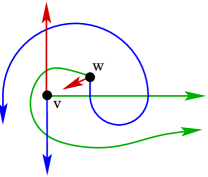
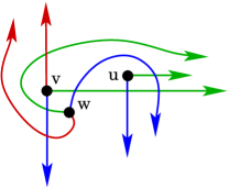
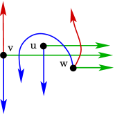
Proposition 13.
The system is an infeasible set of rotations.
Proof.
The table of types for the given permutations must be of the following form:
Looking at the subtable
{ytableau}
W_1 & W_3
\none B_α
corresponding to
one can realize that there is only one choice for ,
namely . The same figure shows that the
subtable
{ytableau}
B_α & W_2
\none W_1
of again only
allows a unique choice of , namely . This proves
that there is no drawing for this set of rotations.
∎
Let be the assignment of types in corresponding to the outer drawing of with outer vertices . Similarly, let be the table corresponding to and the table corresponding to . Note that these assignments determine the rotation system . An assignment of types in to every pair of vertices in translates to the following assignments :
This table reveals a dependency between the types in of every pair of vertices in for different pairs of vertices in . This dependency is instrumental in the upcoming consistency theorems. For an assignment of types in to pairs of vertices in , we will refer to the induced assignments as the projections of .
We are now ready to state our consistency theorem on outer drawings for .
4.1 The consistency theorem for
Theorem 14 (Consistency of outer drawings for ).
Consider the complete bipartite graph with vertex bipartition such that and . Given the assignments of types in for the pairs , , and of vertices in , respectively, there exists an outer drawing of realizing those types if and only if
This directly yields the following corollary.
Corollary 15 (AT-graph realizability).
There exists an algorithm for deciding the existence of an outer drawing of an AT-graph whose underlying graph is of the form .
Proof.
Again, one can check that the three types of pairs in Figure LABEL:fig:sixtypes exactly prescribe which pairs of edges cross, and given the set of crossing pairs, we can reconstruct the type assignment. We can then check that every triple is legal and that the quadruple rule is satisfied in time proportional to the number of triples and quadruples, hence . ∎
Proof of Theorem 14.
Let us first note that one direction of the Theorem is easy: if there exists an outer drawing, then the assignments must be consistent.
We now show that consistency of the type assignments is sufficient for the existence of an outer drawing. Let be the assignment of types in to the pairs of given by Table 1, and let be the corresponding rotations. The consistency of the tables and in the sense of Theorem 10 implies that there are drawings and of realizing the type assignments and . The vertex (the outer vertex with rotation ) and its edges form a non-crossing star in both drawings.
Let the drawing live on plane and live on plane and consider a fixed homeomorphism between the planes. There is a homeomorphism such that mapping via to yields a superposition of the two drawings with the following properties.
Corresponding vertices are mapped onto each other.
The stars of are mapped onto each other, i.e., the edges at of the two drawings are represented by the same curves.
At each vertex the rotation is correct, i.e., we see the edges to in clockwise order.
The drawing has no touching edges, i.e., when two edges meet they properly cross in a single point.
The drawing obtained by superposing and is an outer drawing of . We color the edges of as in our figures, for example the edges incident to are the green edges. In each color class of edges is a non-crossing star. For the blue and the green this is true because the edges come from only one of and . For the red star it is true due to construction. Moreover, all the red-blue and red-green crossings are as prescribed by the original table . The problem we face is that there is little control on blue-green crossings. Let be the red, green, and blue edge of .
Claim: For all , the parity of the number of crossings between and in is prescribed by , i.e., if requires a crossing between two edges, then they have an odd number of crossings and an even number of crossings otherwise.
Consider the curves and . The rotations prescribe whether the number of intersections of the two curves is odd or even. Hence, the parity is respected by . The crossings of the pairs , in are as prescribed by . Hence, the parity of the number of crossings of and in is also prescribed.
Because the rotation at in is correct we also note: If and cross, then the number of crossings is even. Hence, if has no pair of a green and a blue edge crossing more than once, then is an outer drawing realizing the types given by .
Now consider a pair of edges and crossing more than once, is allowed. Use a homeomorphism of the plane to make a horizontal straight line segment, see Figure LABEL:fig:meander. (In the literature intersection patterns of two simple curves in the plane are often called meanders. They are of interest in enumerative and algebraic combinatorics.)
The intersections with subdivide into a family of arcs and two extremal pieces. A blue arc defines an interval on the green edge, this is the interval of the arc. An arc together with its interval enclose a bounded region, this is the region of the arc.
Fact. Apart from intersecting intervals any two regions of arcs over a fixed green edge are either disjoint or nested. Because blue edges are pairwise disjoint this also holds if the arcs are defined by different blue edges.
26meanderA meander with 7 empty lenses.
An inclusionwise minimal region of an arc is a lens. Since has a finite number of crossings and hence a finite number of regions we have:
Fact. Every region of an arc contains a lens.
Consider a lens formed by pair of a green and a blue edge in . Suppose that is an empty lens, i.e., there is no vertex inside of . It follows that the boundary of is only intersected by red edges, moreover, if a red edge intersects the boundary of on the green side, then also intersects on the blue side. Therefore, we can make and switch sides at and with small deformations at the two crossings get rid of them. It is important to note that the switch at a lens does not change the types. In particular after the switch the drawing still represents assignment .
Apply switching operations until the drawing obtained by switching has the property that every lens in contains a vertex.
In the following we show that has no lens. For the proof we use that the table corresponding to also has to be consistent. Since has no lens we conclude that it is an outer drawing that realizes the types given by . The existence of such a drawing was the statement of the theorem. ∎
Let be a drawing with the property that every lens contains a vertex. Before going into the proof that there is no lens in we fix some additional notation. For a given green edge the regions defined by blue arcs over can be classified as above, below, and wrapping. A wrapping region is a region with one contact between and from above and one contact from below.
Lemma 16.
There is no wrapping region.
Proof.
Let be the wrapping region formed by a blue edge wrapping around and note that . If the wrapping blue edge is , then has to intersect one of and to leave the region. This is not allowed. If the wrapping blue edge is with , then has to intersect one of and to leave the region. Again, this is not allowed. ∎
With a similar proof we get:
Lemma 17.
Vertex is not contained in the region defined by an arc of over .
Proof.
The green edge of would be trapped in such a region. ∎
For a region defined by an arc on we speak of a forward or backward region depending on the direction of the arc above . Formally: label the crossings of and as according to the order on . Arcs correspond to consecutive crossings. An arc is forward if crossing is to the left of crossing on , otherwise it is backward. The permutation of obtained by reading the crossings from to along is called the meander permutation and denoted .
A region is a relative lens for and if it is above or below and minimal in the nesting order of regions defined by and . In the sequel we sometimes abuse notation by talking of lenses when we mean relative lenses.
Proposition 18.
For all , the green and blue edges of do not cross in .
Proof.
If and cross, then there is at least one blue arcs on over and, hence, there are regions.
From the order of the three outer vertices and the fact that has no crossing with the two other edges of we conclude that at the last crossing of and the blue edge is crossing downwards.
Since at the first crossing the blue edge is crossing upwards there is an arc and consequently also a lens above .
Suppose there is a forward lens above . Let be a vertex in the lens. Vertex is below the line of in the green-red arrangement. Hence, either or and . Vertex is below the forward arc of forming the lens. Hence, it is below the line of in the red-blue arrangement, and either or and . From Table 1 we infer that the only legal assignment is and the projections are and . However, there is no consistent choice for the order of and in . This shows that there is no forward lens above .
Now let be a backward lens above . Let be a vertex in the lens. We distinguish whether the last crossing on the blue edge is to the right/left of the lens on , see Figure LABEL:fig:Fall2+3.
22Fall2+3The two cases for a backward lens above . Dashed curves indicate the order of some crossings along the corresponding edges.
Suppose the last crossing on the blue edge is to the right of the lens, Figure LABEL:fig:Fall2+3 (left). To get from the arc to the edge has to cross upwards at some crossing left of . The edge has to stay disjoint from , therefore, after crossing to leave the lens it has a second crossing left of . The edge has a crossing with in the arc and another one between and . Now consider the edge . If it leaves the lens through , then it has entered a region whose boundary consists of a piece of and a piece of . Edge is disjoint from and it has already used its unique crossing with . Hence, has to leave the lens through the blue arc on . In this case, however, enters a region whose boundary consists of a piece of and a piece of . Again is trapped. Hence, this configuration is impossible.
Suppose the last crossing on the blue edge is to the left of the lens, Figure LABEL:fig:Fall2+3 (right). To get from to the backward arc edge has to cross downwards at some crossing right of . Let be a vertex in the region of some blue arc below with the property that . The edges and both need at least two crossings with the union of and . Hence, they both cross and . The order of the red edges at implies . Matching these data with the drawings of Figure LABEL:fig:sixtypes we find that and . These types together with the already known permutation imply that and also equal . Hence, the triple is a uniform system, and we must have . Since edge has to follow the ‘tunnel’ prescribed by there is a crossing of edges and . There is also a crossing of and . However, neither in nor in we see crossings of with and . Hence, again the configuration is impossible. ∎
We now come to the discussion of the general case.
Proposition 19.
For all , there is no lens formed by and in .
Our proof of this proposition unfortunately depends on a lengthy case analysis, an outline of which is given in the following subsection.
4.2 Outline of the Proof of Proposition 19
Suppose that there is a lens formed by and in . From Proposition 18 we know that . In fact the proposition implies that the star of every vertex is non-intersecting. For emphasis we collect this and the other restrictions on crossings in in a list.
(1) Edges of the same color do not cross.
(2) Edges of different color that belong to the same vertex do not cross.
(3) Red edges have at most one intersection with any other edge.
These properties will be crucial throughout the argument. We also know that there are no wrapping regions (Lemma 16) and the vertex in a region or lens is always different from the vertices of the edges defining the region (Lemma 17).
In section 4.3.1, we discuss eight configurations that may appear in a meander of over . The eight configurations shown in Figure LABEL:fig:eight-configs correspond to the simplest meanders for the following three binary decisions:
Vertex is above/below edge .
The last crossing is to the left/right of the first crossing.
At the last crossing is cutting upward/downward.
For example the meander labeled VII corresponds to below/left/up. In the case discussion we impose additional conditions on vertices that are contained in the regions defined by arcs of over . These conditions either ask for or for . The conditions are so that they are satisfied for free if the respective regions are relative lenses of over . In each of the cases we show that the projections yield an illegal table. Hence the configurations do not appear in the drawing .
14eight-configsThe eight configurations for the first phase of the case analysis.
In the second part we use the results from the first part to show that meanders of the drawing have no inflections, i.e., in the meander permutation we never see and on the same side of . This is split in the following two lemmas. The first, easy one, is the following.
Lemma 20.
If a meander permutation has an inflection, then it has one of the four turn-back patterns shown in Figure LABEL:fig:back-configs.
Proof.
Suppose that a meander permutation has an inflection at . We discuss the case where and the blue arc of is above . All the other cases can be treated with symmetrical arguments. First note that , otherwise, is in the region defined by the arc . This is impossible (Lemma 17).
Now suppose that . Let be a vertex in the region defined by the arc . Confined by the edge has to cross at least three times and it contains an arc whose region contains . This is impossible (Lemma 17). Hence, and the meander contains the second of the turn-back patterns shown in Figure LABEL:fig:back-configs. Other cases of inflections are related to the other cases of turn-back patterns. ∎
The proof of the second lemma involves a delicate case analysis and is deferred to Subsection 4.3.2.
Lemma 21.
A meander permutation has no turn-back.
14back-configsThe four turn-back pattern.
The consequence of Lemma 21 is that the meanders in are very simple, their meander permutations are either the identity permutation or the reverse of the identity. In particular every arc defines a relative lens. It then follows that each meander in can be classified according to the three binary decisions mentioned above. Hence, it falls into one of the configurations that have been discussed in Subsection 4.3.1. The additional conditions are satisfied because the arcs all define relative lenses. Hence, there are no nontrivial meanders, i.e., every pair of a green and a blue edge crosses at most once in . This concludes the proof of Proposition 19.
4.3 Case analysis for the proof of Proposition 19
4.3.1 The eight basic configurations
We now deal with special instances of the configurations from Figure LABEL:fig:eight-configs.
Case I. The first intersection along is downwards and the last intersection is upwards and to the right of the first intersection along .
Its last intersection with being upward forces to intersect on its final piece. Therefore, edge has to turn around as shown in Figure 2. Now consider , its first crossing (among those relevant to the argument) has to be with . With this crossing, however, gets separated from its destination by the union of and . Therefore, this case is impossible.
{ytableau} \none[w] & A B
\none \none[u] A
\none \none \none[v] .
Case II. The first intersection along is upwards and the last intersection is downwards and to the right of the first along and there is a forward arc of above whose region contains a vertex .
Edge has to turn around and also has to cross , see Figure 4. Now consider a vertex in a forward region of above . Vertex is not under an arc of (Lemma 17) and there is at most one crossing of and . Therefore, behaves as shown in the sketch, i.e., . Also . From the intersections of green and blue edges we conclude that the projections are as given by the table on the right. This table is not legal. Hence, this case is impossible.
{ytableau} \none[u] & B A
\none \none[w] N
\none \none \none[v] .
Case III. The first intersection along is upwards and the last intersection is downwards and to the left of the first along and there is a backward arc of above whose region contains a vertex .
Edge has to stay below . Now consider a vertex in a backward region of above . Vertex is not under an arc of and we exclude the configuration of Case I. Therefore, behaves as shown in Figure 3, i.e., . It follows that has to stay above and . From the intersections of green and blue edges we conclude that the projections are as given by the table on the right. This tables is not legal. Hence, this case is impossible.
{ytableau} \none[v] & N B
\none \none[w] A
\none \none \none[u] .
Case IV. The first intersection along is downwards and the last intersection is upwards and to the left of the first along and there is a backward arc of below whose region contains a vertex .
Edge has to cross and the other edges of have no intersections with edges of . Edge either turn around or it crosses . In the first case has turn around . Now, has to cross and gets separated from its destination by the union of and . Hence, there is no possible routing for edge respecting the restrictions on crossings in . In the second case crosses and . From the green edges we obtain . The intersections of green and blue edges, see Figure 5 imply that the projections are as given by the table below the figure. This table is not legal. Hence, this case is impossible.
{ytableau} \none[w] & A B
\none \none[x] A
\none \none \none[u] .
Case V. The first intersection along is downwards and the last intersection is downward and to the right of the first. Moreover, along there is a forward arc of below whose region contains a vertex and further to the right a forward arc of above containing a vertex .
If , then edge makes sure that . Therefore, we have Case II with , , and .
If , then . Therefore, we have a Case III.
Now let . Since is crossing downwards we have above and a crossing of with . Therefore .
If , then the intersections of green and blue edges areas shown in Figure 6. The projections are given by the table below the figure. This table is not legal. Hence, this case is impossible. If , then we have Case IV with and . Finally, if , then the green and blue edges behave as shown in Figure 7. Now, would have to cross one of and twice to get to its destination .
{ytableau} \none[u] & A B
\none[w] A A
\none \none[v] B
\none\none \none[x] .
Case VI. The first intersection along is downwards and the last intersection is downward and to the left of the first. Moreover, along there is a backward arc of above whose region contains a vertex and further to the right a backward arc of below containing a vertex .
If , then edge either yields a Case II with or a Case III with . Therefore, .
If , then edge has an arc above or it forms a Case I. Therefore, and the complete order is .
From green edges we get and , see Figure 8. Independent of the entry the resulting table as shown below Figure 8 violates the quadruple rule, Lemma 9. Hence, this case is impossible.
{ytableau} \none[x] & A B A
\none \none[v] B B
\none \none \none[w] \none[u] .
Case VII. The first intersection along is upwards and the last intersection is upward and to the left of the first. Along there is a backward arc of below whose region contains a vertex and further to the right a backward arc of above containing a vertex .
If , then edge either yields a Case I or a Case IV with . Therefore, .
If , then vertices , and are in the configuration of Case II. If , then since otherwise would be in a region of , a violation of Lemma 17. Now and , and is an illegal table.
If , then and the situation is as sketched in Figure 9. Irrespective of or the projections of the remaining 5 pairs yield the partial table shown below the figure. This violates the quadruple rule, Lemma 9. Hence, this case is impossible.
{ytableau} \none[u] & A N—B A
\none \none[v] B B
\none \none \none[x] \none[w] .
Case VIII. The first intersection along is upwards and the last intersection is upward and to the right of the first. Along there is a forward arc of above whose region contains a vertex and further to the right a forward arc of below containing a vertex .
If , then edge either yields a Case I or a Case IV with . Therefore, .
If , then edge yields a Case III with . If , then and , and is an illegal table.
Therefore, and in total , see Figure 10. Also and only the order of and in is not determined. If then otherwise . The resulting table is shown below Figure 10. In the first case the triple yields an illegal subtable. In the second case there is a violation of the quadruple rule, Lemma 9. Hence, this case is impossible.
4.3.2 Proof of Lemma 21
Given suppose that some has a meander over with a turn-back. Among all the turn-backs over choose the one with the turn-back point as far as possible, where is the crossing of the turn-back whose two adjacent crossings are on the same side.
It will be seen in the proof that this specific choice of turn-back substantially simplifies the analysis of two of the cases.
Case TB 1. The turn back corresponds to a substring or to a substring in and the turn-back arc is above .
Let us assume that the substring is so that the turn-back arc is . Let be a vertex in the region of the turn-back arc and let be a vertex in the region of the arc .
The edge is confined by and has a forward arc below . If has a crossing with then we have a Case I. From Lemma 17 it follows that the last crossing of and is downwards and to the right of .
If , then has a backward arc in the interval such that is in the region of arc . The left part of Figure LABEL:fig:caseTB1 shows a schematic view of the situation. Let be a vertex in the region of an arc of above and preceeding along such that . Edges and Lemma 17 force to have its last intersection with downwards and to the right of . Hence and are in the configuration of Case II.
We know that . Let be a vertex below the last forward arc of above . If , then with and are in the configuration of Case V. Otherwise, if , then there is a backward arc of above . Choose a vertex from a backward arc below and to the right of . The right part of Figure LABEL:fig:caseTB1 shows a schematic view of the situation. Edge is forcing to have an arc over .
26caseTB1Illustrations for case TB 1.
If the last intersection of with is downwards and left of the last intersection of and , then with and are in the configuration of Case III.
If the last intersection of with is downwards and right of the last intersection of with , then has to cross twice to reach its destination without intersecting and . The left part of Figure LABEL:fig:caseTB1second shows a schematic view of the situation, the light-blue arc is spanned by two arcs of .
If the last intersection of with is upwards and crosses , then there are two options. The first is that and there is a configuration of Case VII with , , and . The second is , this requires that has a turn-back interior of the original turn-back of before crossing , in this situation shows a Case I or together with a Case III. The right part of Figure LABEL:fig:caseTB1second illustrates this case.
26caseTB1secondMore illustrations for case TB 1.
Case TB 2. The turn back corresponds to a substring or to a substring and the turn-back arc is below .
Let us assume that the substring is so that the turn-back is the arc . Let be a vertex in the region of the turn-back arc and let be a vertex in the region of the arc .
The first intersection of with is left of the turn back point of the meander . The choice of the turn-back as the leftmost implies that has no turn-back. Hence, is the reverse of the identity.
If the last intersection of with is downwards, then this is a Case III with . Otherwise the last intersection is upwards and intersects . Then there is a backward arc of below and a vertex from such an arc together with shows that the situation of Case VII. See Figure LABEL:fig:caseTB2.
26caseTB2Illustrations for case TB 2.
Case TB 3. The turn back corresponds to a substring or to a substring and the turn-back arc is above .
Let us assume that the substring is so that the turn-back is the arc . Let be a vertex in the region of the turn-back arc and let be a vertex in the region of the arc .
The first intersection of with is left of the turn back point of the meander . The choice of the turn-back as the leftmost implies that has no turn-back. Hence, is the reverse of the identity.
If intersects , then with this yields a Case IV. Otherwise there is a backward arc of above . Let be a vertex from such an arc. Now together with and are a Case VI.
Case TB 4. The turn back corresponds to a substring or to a substring and the turn-back arc is below .
Let us assume that the substring is so that the turn-back is the arc . Let be a vertex in the region of the turn-back arc and let be a vertex in the region of the arc .
If intersects this is a Case I. It follows that that . If then and are in the configuration of Case II.
If , then there is a forward arc of below and to the right of . Let be a vertex from the region of such an arc.
We first consider the case . If intersects then with yields a Case VIII. If , then it follows with Lemma 17 that so that they form a Case III. For edge has to turn back as shown in the left part of Figure LABEL:fig:caseTB4. In this configuration has to cross one of and twice to get to its destination .
Now we are in the case and . This requires a backward arc of whose region contains . To the right of this arc there has to be a backward arc above . Let be a vertex from the region of this arc. The situation is shown in the right part of Figure LABEL:fig:caseTB4. If , then so that and form a Case II. If , then either is a Case I or it forms a Case III with .
26caseTB4Illustrations for case TB 4.
5 Outer Drawings with arbitrary
We now generalize our result on consistency of outer drawings for to any .
In the previous section, we defined types for each pair of vertices in in an outer drawing of . Fortunately, we do not need to go beyond the enumeration of the outer drawings of to be able to generalize our result to arbitrary values of .
Theorem 22 (Consistency of outer drawings for ).
Consider the complete bipartite graph with vertex bipartition such that and . Given assignments of types in for each pair of vertices in and each pair of vertices in , there exists an outer drawing of realizing those types if and only if
Proof.
We proceed by induction, suppose that the result holds for some and prove that the result holds for . The base cases for were proved in the previous sections.
From the induction hypothesis, there exists a drawing of realizing the types involving vertices in . Similarly, there exists a drawing of realizing the types involving the two vertices and .
Similarly to what we did in the proof of Theorem 14, we can superpose the two drawings in such a way that the drawings of the two stars corresponding to match. More precisely, let the drawing live on plane and live on plane . Consider a fixed homeomorphism between the planes. There is a homeomorphism such that mapping via to yields a superposition of the two drawings with the following properties:
Corresponding vertices are mapped onto each other.
The stars of are mapped onto each other, i.e., the edges at of the two drawings are represented by the same curves.
At each vertex the rotation is correct, i.e., we see the edges to in clockwise order.
The drawing has no touching edges, i.e., when two edges meet they properly cross in a single point.
The drawing obtained by superposing and is a drawing of , possibly with some multiple crossings. We color the edges of according to the vertex it is incident to, using colors . Each color class of edges is a non-crossing star, and the parity of the number of crossings between two edges of distinct colors is prescribed by the type assignments. Furthermore, since and are proper outer drawings, all pairs of edges crossing more than once have respective colors and for some .
Consider all lenses formed by an edge of color and another edge of color . Such a lens is said to be empty whenever it does not contain any vertex from . It is inclusionwise minimal whenever it does not fully contain any other lens. Consider an empty inclusionwise minimal lens formed by an edge of color and another edge of color .
If an edge of color intersects the lens, it can only cross once. Similarly, it cannot cross the boundary of the lens on more than once, either because , or because otherwise the lens would not be minimal. Another edge of color cannot intersect the lens, because it could only do so by intersecting at least twice, contradicting the minimality of the lens.
Hence all edges intersecting the lens intersect its boundary exactly once on each edge. Therefore we can safely get rid of the two crossings by making and switch sides. The switch at a lens does not change the type assignment. We can perform this iteratively until no empty lens is remaining. We call the final drawing . This drawing has the property that every lens contains a vertex.
We now wish to show that has no lens. For the sake of contradiction, suppose that there is a lens formed by and in . We can apply our previous analysis for the case on the restriction of formed by the edges of color , and , letting red, green, and blue. In particular Proposition 19 holds, and has no lens. Therefore, neither does , which is a suitable outer drawing of . ∎
This yields the following corollary for AT-graphs.
Corollary 23 (AT-graph realizability).
There exists an algorithm for deciding the existence of an outer drawing of an AT-graph whose underlying graph is of the form .
Proof.
We know that the three types of pairs (see Figure LABEL:fig:sixtypes) exactly prescribe which pairs of edges cross, hence given the set of crossing pairs, we can reconstruct the type assignments . From these data, we can consider every 5-tuple , with and , and check that the corresponding drawing of the induced graph is one of the drawings given in Table 1. This can be done in time . If this is correct, we can then check that every triple is legal and that the quadruple rule is satisfied for each . This can be done in time , hence the result. ∎
In fact, this implies that checking consistency on all 6-tuples of vertices is sufficient. This matches the result of Kynčl for complete graphs [14].
6 Extendable and Straight-line Outer Drawings
A simple topological drawing of a graph is called extendable if its edges can be extended into a pseudoline arrangement. We consider the problem of the existence of an extendable outer drawing for a given rotation system. We also further restrict to straight-line drawings. We exploit a connection between topological drawings and generalized configuration of points which was also used by Kynčl [14]. The main result uses the notion of suballowable sequence, as defined by Asinowski [2].
6.1 Extendable Outer Drawings
We will use the notion of allowable sequence. These sequences were introduced by Goodman and Pollack in a series of papers [6, 7, 8] as an abstraction of the sequences of successive permutations obtained by projecting a set of points in on a rotating line. A good summary of this and related notions can be found in Goodman’s article in the Handbook of Discrete and Computational Geometry [21]. We restrict to simple allowable sequences, corresponding to point sets with no three points on a line and such that no two pair of points determine the same slope.
A sequence of permutations of an -element set, with , is an allowable sequence if for all , and are reverse of each other, each consecutive pair of permutations differ only by a single adjacent transposition, and every pair of element is reversed exactly twice in the sequence.
We will also need the following additional definition: A Generalized configuration is a pair such that is a collection of points in the projective plane and is an arrangement of pseudolines, one of which is the pseudoline at infinity , satisfying the following conditions:
-
•
every pair of points of lie on a pseudoline of ,
-
•
each pseudoline in contains exactly two points of , except ,
-
•
does not contain any point of .
We say that an allowable sequence on an -element set is realized by a generalized configuration on points when the successive permutations of the sequence correspond to successive segments of the pseudoline , and the transposition between a pair of permutations corresponds to the intersection of with the pseudoline containing the two corresponding points. In particular, we observe that if a permutation is realized at some point , then can be connected by additional pseudolines to the other points in the radial order prescribed by .
The following result is known.
Theorem 24 (Goodman and Pollack [7], Thm. 4.4).
Every allowable sequence can be realized by a generalized configuration.
This directly yields that allowable sequences exactly encode which are the achievable rotation systems for our drawings. We first define suballowable sequences, see Asinowski [2]: A sequence of permutations of an -element set is said to be a suballowable sequence if there exists an allowable sequence admitting as a subsequence.
Theorem 25.
Given a sequence of permutations of elements, there exists an extendable outer drawing of with this rotation system if and only if is a suballowabe sequence.
Proof.
First, suppose that the rotation system is a suballowable sequence. Then by definition there exists an allowable sequence admitting it as a subsequence. Then from Theorem 24 there exists a generalized configuration on points realizing this sequence. The points form the set . For each permutation , there exists a point on that can be connected by additional pseudolines to the points of in the order prescribed by . These points form the set . By keeping only the inner segments of the pseudolines connecting every point of with all points of , we obtain an extendable outer drawing satisfying our conditions.
Now suppose there exists an extendable outer drawing. Consider the generalized configuration obtained as follows. First, we extend the edges between the points of and into pseudolines, which is possible from the extendability of the drawing. Then we connect the points of by the pseudoline at infinity. Finally, by iteratively applying Levi’s enlargement Lemma, we can also connect every pair of points in by a new pseudoline. The order in which each point of is connected to all points of realizes one permutation in the allowable sequence defined by the generalized configuration. The collection of such permutations therefore forms a suballowable sequence. ∎
Note that since suballowable sequences can be recognized efficiently (see [2]), this directly yields a polynomial-time algorithm for deciding whether there exists an extendable outer drawing realizing a given rotation system.
6.2 Straight-line Outer Drawings
We have a direct equivalent statement for straight-line outer drawings.
Theorem 26.
Given a sequence of permutations of elements, there exists an straight-line outer drawing of with this rotation system if and only if is a suballowable sequence that can be realized by an actual point arrangement.
This does not yield an efficient algorithm, since deciding whether a given allowable sequence can be realized by an arrangement of straight lines is a hard problem [20, 17, 10]. The problem, however, is tractable in the special case where . This is due to the fact that we can fix the orientation of the three sets of edges. There are two cases to consider. If the suballowable sequence can be extended into an allowable sequence such that the three permutations appear in the first permutations of the whole sequence, then there exists a straight-line outer drawing with , and . This corresponds to the case where the three projection directions span less than a half-circle. Otherwise there exists a drawing with , and .
We first give an example showing that there are rotation systems for that are suballowable sequences but do not admit a straight line outer drawing. Up to renaming, this example is the same as Asinowski’s example of nonrealizable suballowable sequence ([2], Proposition 8). We give the proof for completeness. Furthermore, our proof directly indicates how to solve the straight-line realizability problem in the case .
Theorem 27.
The triple of rotations given by:
is a suballowable sequence, but is not realizable with straight lines.
45non-stretch-smallAn outer drawing of the system from Theorem 27.
Proof.
Figure LABEL:fig:non-stretch-small shows an outer drawing of the system. Suppose that the system is stretchable, then there is a drawing with , and , i.e., with horizontal rays, vertical rays, and rays of slope 1. The coordinates of a vertex are denoted .
From we deduce the inequality . Similarly and . We will refer to these inequalities as I1, I2, and I3 in this order.
From we get , , and . Finally, from we get , , and . These six inequalities are the helper inequalities.
Adding I1 and I2 and rearranging terms we obtain
Replacing , , and on the left side and , , and on the right side using the six helper inequalities we obtain . This contradicts I3. ∎
A straight line outer drawing of such a rotation system can be regarded as a tropical arrangement of lines. We refer to [16] for an introduction to tropical geometry. Such outer drawings can consequently be regarded as tropical arrangements of pseudolines. Restated as a result in tropical geometry Theorem 27 tells us that there are non-stretchable tropical arrangements of pseudolines.
The classical construction of a simple non-stretchable example of pseudolines due to Ringel is based on the 9 lines of a Pappus configuration. In [19] tropical versions of Pappus are discussed. They note that a configuration on 9 tropical lines which can be obtained from the configuration of Theorem 27 by replacing points by triple incidences of lines with is a valid tropical version of Pappus’ Theorem.
The stretchability problem for a tropical arrangements of pseudolines is polynomial-time solvable, as it boils down to the feasability of a linear program. The proof of Theorem 27 indicates how to set up such a linear program.
7 Open problems
A problem that remains for is to find a good description of all outer drawings for a given pair of rotations. We state the same problem differently:
Problem 1.
For a given pair of permutations characterize all consistent assignments of types with the property that if in both permutations, then , and if and , then .
The simpler case where (hence all types are in )
is covered by Corollary 5, which provides a bijection
with combinatorial structures counted by Schröder numbers.
The following natural question also remains unsolved:
Problem 2.
For a given triple of rotations, can we decide in polynomial time whether there exists a consistent assignment of types?
The problem could be generalized to arbitrary : how hard is it to decide
whether there exists an outer drawing of for a given rotation system?
We answered this question partially, by showing that it is polynomial-time
decidable when the drawing is further required to be extendable.
We also note that outer drawings are not really enlightening with respect to crossing numbers, as minimally crossing outer drawings of are easy to describe. It can be checked that by drawing the vertices of on a line so that vertices of see them in some order, and the other vertices see them in the reversed order, we achieve the minimum number of crossings. This minimum has value exactly .
Further insight into crossing numbers could be gained by considering the obvious remaining problem of generalizing our analysis to general simple topological drawings, dropping the outer property.
Acknowledgments
This work was started at the Workshop on Order Types, Rotation Systems, and Good Drawings in Strobl am Wolfgangsee (Austria) in 2015. We thank the organizers from TU Graz as well as the participants for fruitful discussions. Special thanks go to Pedro Ramos who suggested to look at complete bipartite graphs.
S. Felsner also acknowledges support from DFG grant Fe 340/11-1.
References
- [1] B. M. Ábrego, O. Aichholzer, S. Fernández-Merchant, P. Ramos, and G. Salazar, The 2-page crossing number of Kn, Discrete & Computational Geometry, 49 (2013), 747–777.
- [2] A. Asinowski, Suballowable sequences and geometric permutations, Discrete Mathematics, 308 (2008), 4745–4762.
- [3] J. Blažek and M. Koman, A minimal problem concerning complete plane graphs, in M. Fiedler, editor: Theory of graphs and its applications, Czech. Acad. of Sci., 1964, 113–117.
- [4] R. Christian, R. B. Richter, and G. Salazar, Zarankiewicz’s conjecture is finite for each fixed , J. Comb. Theory, Ser. B, 103 (2013), 237–247.
- [5] S. Felsner, Geometric Graphs and Arrangements, Advanced Lectures in Mathematics, Vieweg Verlag, 2004.
- [6] J. E. Goodman and R. Pollack, On the combinatorial classification of nondegenerate configurations in the plane, J. Comb. Theory, Ser. A, 29 (1980), 220–235.
- [7] J. E. Goodman and R. Pollack, Semispaces of configurations, cell complexes of arrangements, J. Comb. Theory, Ser. A, 37 (1984), 257–293.
- [8] J. E. Goodman and R. Pollack, The complexity of point configurations, Discrete Applied Mathematics, 31 (1991), 167–180.
- [9] F. Harary and A. Hill, On the number of crossings in a complete graph, Proc. Edinburgh Math. Soc., 13 (1963), 333–338.
- [10] U. Hoffmann, Intersection Graphs and Geometric Objects in the Plane, PhD thesis, TU Berlin, 2016.
- [11] J. Kratochvíl, A. Lubiw, and J. Nešetřil, Noncrossing subgraphs in topological layouts, SIAM J. Discrete Math., 4 (1991), 223–244.
- [12] J. Kratochvíl and J. Matoušek, NP-hardness results for intersection graphs, Commentationes Math. Univ. Carol., 30 (1989), 761–773.
- [13] J. Kynčl, Simple realizability of complete abstract topological graphs in P, Discrete & Computational Geometry, 45 (2011), 383–399.
- [14] J. Kynčl, Improved enumeration of simple topological graphs, Discrete & Computational Geometry, 50 (2013), 727–770.
- [15] J. Kynčl, Simple realizability of complete abstract topological graphs simplified, in Graph Drawing and Network Visualization - 23rd International Symposium, GD 2015, Los Angeles, CA, USA, September 24-26, 2015, Revised Selected Papers, 2015, 309–320.
- [16] D. Maclagan and B. Sturmfels, Introduction to tropical geometry, vol. 161 of Graduate Studies in Mathematics, AMS, 2015.
- [17] N. E. Mnëv, The universality theorems on the classification problem of configuration varieties and convex polytopes varieties, in Topology and geometry—-Rohlin Seminar, vol. 1346 of LNM, Springer, 1988, 527–543.
- [18] J. Pach and G. Tóth, How many ways can one draw a graph?, Combinatorica, 26 (2006), 559–576.
- [19] J. Richter-Gebert, B. Sturmfels, and T. Theobald, First steps in tropical geometry, in Idempotent mathematics and mathematical physics, vol. 377 of Contemp. Math., AMS, 2005, 289–317.
- [20] P. W. Shor, Stretchability of pseudolines is NP-hard, in Applied geometry and discrete mathematics, vol. 4 of DIMACS, AMS, 1991, 531–554.
- [21] C. D. Tóth, J. O’Rourke, and J. E. Goodman, eds., Handbook of Discrete and Computational Geometry, Second Edition, Discrete Mathematics and Its Applications, Chapman and Hall/CRC, 2004.
- [22] K. Zarankiewicz, On a problem of P. Turán concerning graphs, Fundamenta Mathematicae, 41 (1954), 137–145.