Non-destructive photon detection using a single rare earth ion coupled to a photonic cavity
Abstract
We study the possibility of using single rare-earth ions coupled to a photonic cavity with high cooperativity for performing non-destructive measurements of photons, which would be useful for global quantum networks and photonic quantum computing. We calculate the achievable fidelity as a function of the parameters of the rare-earth ion and photonic cavity, which include the ion’s optical and spin dephasing rates, the cavity linewidth, the single photon coupling to the cavity, and the detection efficiency. We suggest a promising experimental realization using current state of the art technology in Nd:YVO4.
I Introduction
The ability to detect photonic qubits non-destructively would be very useful for many quantum information applications, including long-distance quantum communication Sangouard et al. (2011); Boone et al. (2015) and photonic quantum computing Knill et al. (2000); Humphreys et al. (2013); O’Brien et al. (2003). One approach for non-destructive measurement is to use a single atom or ion that is coupled with high cooperativity to an optical cavity Turchette et al. (1998). In particular, Ref. Duan and Kimble (2004) suggested realizing a quantum controlled phase-flip (CPHASE) gate between the photon and the ion based on the fact that, depending on the state of the ion, the photon would either be reflected unchanged or with a -phase shift. The resulting entanglement between the photon and the ion can be used to detect the photon through readout of the ion’s state. These ideas have recently been realized in a series of impressive experiments with single trapped atoms inside free-space high-finesse cavities Reiserer et al. (2013, 2014); Kalb et al. (2015); Hacker et al. (2016).
For more robust and scalable technologies, it would be useful to be able to implement similar protocols in the solid state. A single rare-earth ion (REI) doped into a crystal is very similar to an optically trapped single atom, when the crystal is cooled to cryogenic temperatures in order to avoid dephasing via coupling to phonons. Rare-earth doped crystals have been successfully used for optical quantum memories Lauritzen et al. (2010); Afzelius et al. (2010a); Hedges et al. (2010), and have been suggested for scalable quantum computing Wesenberg et al. (2007). A scheme for performing non-destructive measurements utilizing an ensemble of rare-earth ions coupled to a bulk crystalline waveguide has recently been suggested Sinclair et al. (2015). It is also now possible to observe single rare-earth ions in bulk crystal Kolesov et al. (2012); Yin et al. (2013); Ahlefeldt et al. (2013); Utikal et al. (2014); Eichhammer et al. (2015), and to map between ion-spins and a photon’s polarization Kolesov et al. (2013). There has recently been success in coupling Nd ions doped into yttrium orthosilicate (YSO) Zhong et al. (2015) and yttrium orthovanadate (YVO) Zhong et al. (2016) crystals with photonic crystal cavities that were fabricated out of bulk crystal. The advantage of using rare-earth ions compared to other solid state emitters like nitrogen-vacancy centers in diamond or semiconductor quantum dots is that they combine narrow inhomogeneous broadening, low spectral diffusion, close to transform-limited optical line-widths and spin states with a long coherence time.
Using rare-earth ions doped into photonic cavities to realize CPHASE gates was first suggested by McAuslan et al. (2011). Here we perform an in-depth analysis of this idea with a focus on the implementation of non-destructive photon detection, including a detailed scheme and an accounting for the likely fidelity. Rare-earth ions coupled to nano-photonic resonators will enable an on-chip platform where single ions act like optically addressable single quantum bits that can be interfaced via photons, with the possibility for on-chip photon storage into optical quantum memories made from the same atomic species.
The paper is organized as follows. In section II we introduce the protocol for creating the conditional phase shift. In section III we explain how this setup can be used for quantum non-destructive measurements. In section IV we discuss how the state of the ion can be read out. In section V we calculate the fidelity of the non-destructive measurement as a function of the rare-earth ion and photonic cavity parameters, including the dephasing of the ion’s optical and spin transitions, the linewidth of the cavity, the single photon coupling between the ion and the cavity, as well as the probability of successful read out. In section VI we discuss a specific implementation of the protocol in Nd:YVO4 crystals. In section VII we give some concluding remarks.
II Conditional Phase Shift
Consider a single rare-earth ion doped directly into a photonic crystal cavity, where one side is partially transparent and the other end is perfectly reflecting. The incoming photon will interact with the ion-cavity system. If the ion is strongly coupled to the cavity, the photon will reflect off the cavity with a phase that depends on the state of the ion. If the ion is not coupled to the cavity, the photon will enter the cavity and receive a -phase shift. If the ion is coupled to the cavity, the cavity will not be impedance matched with the photon, so the photon will reflect off the cavity without entering and will not have a phase shift. Thus the reflected photon gains a phase that is dependent on whether the ion is in a state that interacts with the cavity, which creates a CPHASE gate.
If we assume the input field is weak enough to have a low probability to excite the ion, we can write down a set of quantum Langevin equations McAuslan et al. (2011):
| (1) | |||
| (2) |
Here is the decay rate of the cavity, is the detuning of the incoming photon from the cavity, is the decoherence rate of the ion, g is the single photon coupling between the REI and the cavity, is the photon excitation amplitude, is the atomic excitation amplitude, and is the amplitude of the photon incident on the cavity. We will see that the probability of a single photon entering the cavity and exciting the atom is inversely proportional to the single ion cooperativity which we take as large and thus justify our assumption that the atom remains in its ground state.
These equations can be solved under the assumption that the input field has a narrow frequency range with respect to the dynamics of the atom-cavity system such that we can perform adiabatic elimination, i.e. . Assuming there is no initial excitation of the atom then the output photon can be expressed as a function of the input photon.
| (3) |
This expression covers two cases, when the ion is in resonance with the cavity, we can take , which will give us the case where the photon does not enter the cavity. Then when we do not want the ion interacting with the cavity, we put the ion into a metastable state that is far detuned from the cavity with , which will allow the photon to enter the cavity and receive a -phase shift. In general, for a REI, both of the ground states will interact with an upper transition, for the same polarization of applied light, which is not necessarily the case for a trapped ion, which is why we need to consider the case of the non-resonant transition rather than just assuming that one state of the ion does not interact with the cavity at all as Duan and Kimble (2004); McAuslan et al. (2011) assumes.
Both transitions being allowed is one difference between the protocol in trapped atoms and REI. Another difference is that REI tend to have weaker dipole moments than those of trapped atoms. For trapped atoms that are strongly coupled to cavities it is typical to be in the “good cavity” regime where , but for the REI-cavity system this is unlikely. Since the ion-cavity coupling is usually weaker due to smaller dipole moments. The REI-cavity system is instead in what is called the “bad cavity” regime McAuslan et al. (2011) where and yet the single photon cooperativity is still high with .
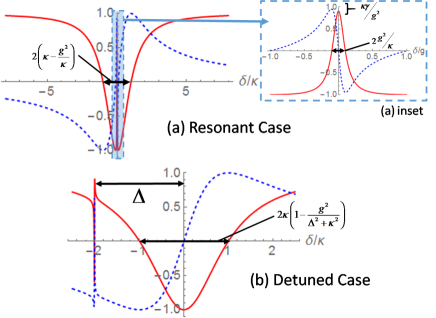
In order to understand the details of the CPHASE protocol, we develop a clear analytic picture, as shown in Fig.1. Using the decaying-dressed state analysis from Anisimov and Kocharovskaya (2008); O’Brien et al. (2011), we can analyze Eq.(3) to get simple analytic expression for the amount of the phase shifts and the bandwidth over which they occur. In the bad cavity limit, we can expand Eq.(3) into partial fractions. If the ion is in resonance such that , then
| (4) |
The coupling between the atom and cavity creates a broad region with a HWHM of where the photon enters the cavity and gets a -phase shift with a narrow central feature with HWHM of where the interaction with the atom stops the photon from entering the cavity as shown in Fig. 1(a). For near resonance , the ratio of output and input is close to unity when the single photon cooperativity is high
| (5) |
such that an incoming photon is reflected with no phase change. The reflectivity is not exactly unity because a small amount of the photon enters the cavity and is scattered by the atom.
Now we consider when the ion is in the far-detuned state such that
| (6) |
Since the detuned transition may be weaker due to the partial selection rules of the REI we label the cavity-ion coupling for this transition as to distinguish it. If the atom is in its far-detuned state, then the atomic resonance is far-detuned from the photon frequency with , then there is the cavity interaction centered at and a Fano resonance as shown in Fig. 1(b). The first term has a HWHM of and is due to interaction with the cavity, where the photon enters the bad cavity and then leaves with a -phase shift. The second feature is too far detuned to interact directly with the photon. The ratio for a photon with frequency near the cavity resonance is then
| (7) |
The imaginary term is due to residual far-detuned interaction with the ion, which causes a small phase shift of the photon.
Eq.(3) was derived in the adiabatic limit, dropping the time derivatives of the field and atom. Now consider the case where the photon that reflects off the cavity has a finite bandwidth. Taking a Gaussian pulse with pulse duration HWHM is centered at , Eq.(3) can be averaged over the bandwidth of the pulse under the assumption that . This updates Eq.(5) to
| (8) |
such that it now applied to a finite pulse.
III Non-destructive photon measurement
This setup can be used as a method of entangling photons and single rare-earth ions, for use in quantum computing or for non-destructive photon detection. The basic idea is similar to Reiserer et al. (2014). To generate entanglement we first initialize the ion in a superposition of the ground states, then an incoming photon will be put in a superposition state with a -phase shift entangled with the ion. Then by performing a rotation and measurement on the ion state, we can read out whether there was an incoming photon.
First, prepare the ion in a superposition of the two ground states
| (9) |
where is the ground state of the far-detuned transition between and cavity, and is the ground state of the resonant transition between and . with the cavity. For a REI, this superposition can be created by using a pair of externally applied far-detuned Raman pulses to drive the system into this state. For a single REI this is more straightforward then for a crystal with a high density of ions, because with a high density of ions, it is required to use extensive hole-burning Rippe et al. (2005), to isolate those spins with a particular frequency. The prepared superposition state can live only as long as the coherence remains, so once we turn off the external pulses we will only have a limited time to perform the non-destructive photon measurement depending on the decoherence rate of the spin transition.
The photon that reflects off of the cavity can be in a superposition state of a single photon and the state with no photon is with an arbitrary phase such that our photon state is
| (10) |
which as we showed in Sect.II, will give a -phase shift to the state where there is both a photon present and the atom is in . This leads to a combined entangled state:
| (11) |
Then performing a /2 rotation of the ion state which once again can be performed with external pulses such that
| (12) | ||||
| (13) |
Then the ideal entangled state is
| (14) |
Finally a measurement is made on the atom in the population basis.
This completes our non-destructive measurement, since now by detecting the photons emitted into the cavity, we know if a photon reflected off of the cavity. The photon reflected off the cavity may have a phase shift, but is otherwise unchanged by the process. Normally, detecting a photon necessitates its destruction. With a unheralded time bin qubit, a non-destructive photon measurement can be made on both bins in order to know there is a photon in one without destroying the qubit Sinclair et al. (2015). With a heralded time bin photon, we could entangle the REI with the time bin qubit by limiting our QND measurement to one of the time bins.
IV Read out
In order to identify that a photon has reflected off of the cavity it is necessary to detect that the ion was in the state . This can be accomplished by optically pumping this level to the excited state with a narrow band laser and then detecting the fluorescence. For a REI the probability of detection is limited by the branching ratios for fluorescence from the excited state to lower energy levels. This is greatly improved by interaction with the cavity, due to the Purcell effect. The Purcell effect is due to the density of states for the cavity being much larger than the density of states for free space. The rate of emission into the cavity is enhanced by the Purcell factor defined as:
| (15) |
where is the wavelength of the cavity, is the refractive index of the crystal, is the quality factor of the cavity, and is the mode volume of the cavity. For a two level atom, the Purcell factor is related to the single ion cooperativity through the ratio of the radiative line width to the total linewidth through , and thus is always larger than . Thus, for there is a much higher chance that fluorescence will be into the cavity mode, rather than free space. If a single rare earth ion is strongly coupled to a high quality photonic crystal cavity, it is possible to reach Purcell factors greater than . Now in a multi-level atom, there will be multiple channels for fluorescence, the probability in the bare ion to fluoresce in the desired channel is given by the branching ratio for that transition. This probability is enhanced by interaction with the cavity such that
| (16) |
Then for example if we had a branching ratio of and , this would give the probability of fluorescence into the cavity as .
Utilizing preferential emission into the cavity, means the photons emitted into the cavity must be detected. So sometime after the time-bin photon reflects off the cavity, the optical path should be switched such that any future photons emitted from the cavity can be detected by a single photon detector. Then the detection is limited by the efficiency of the single photon detector, which we will assume is .
When , the best way to read out the atomic state is to drive the cavity transition itself (-polarized) and rely on the Purcell effect to preferentially fluoresce into the cavity mode in order to have a cycling transition such that if the ion is in the proper state, many photons are emitted into the cavity. If the ion does not fluoresce into the cavity, the photon is lost and the population cycling ends, which means this method has a maximum efficiency of .
One issue with this method is there is a possibility that photons from the pump will be scattered into the cavity mode. This means that, besides detector dark-counts, scattering will also lead to false-positives. In this case, it is necessary to detect some minimum number of photons , in order to discriminate against false positives. Then the detection efficiency can be written as a sum over the number of photons created in the cavity, with a factor giving the probability of photons being emitted and a factor determining the probability of detecting at least photons when photons are in the cavity
| (17) |
For example, if we choose to detect photons, to try to reduce dark counts, with and , then the detection efficiency will be . If it is determined that more photons are needed to get a signal above the background of detector dark-counts and scattered light, then this efficiency does not decrease much, for , the efficiency is only a little lower . Thus for the rest of the paper, we will assume this read-out method.
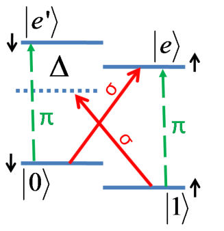
The entire detection process must be completed before the state , relaxes to the ground state , but the spin relaxation time , is quite long for rare-earth ions kept below 7K, on the order of 100ms. This gives plenty of time to complete the read-out process. Another concern is the possibility of false positives due to accidentally driving state to emit a photon into the cavity. Since the Purcell effect guarantees a high probability that a photon will be emitted into the cavity if the off-transition is driven to the alternate excited state labeled in Fig.2, we just need to calculate the probability to excite the far-detuned transition. The pump laser needs to have a Rabi frequency that is large enough to achieve Rabi flopping with a significant amount of the population reaching the excited state in order to have fast read-out. Here is the dipole moment of the driven transition, is the pump electric field, and is Planck’s constant divided by . At the same time a larger leads to quicker read-out but also leads to a higher chance of driving the off-transition which may lead to a false positive. A good compromise is to take , but of similar magnitude. Any lower will lead to lower excited state population, which slows down the emission while the probability of exciting the off transition is equal to:
| (18) |
where is the average number of cycles that the driven transition goes through which for is , and there is a factor to account for the possibility that the off-resonant transition is weaker than the resonant transition. We will estimate for our different schemes in Sect.VI, but in general it can be kept small enough to not hamper the fidelity. At the same time, the selection rules for driving transitions in the REI are not perfect, such that sigma polarized light may still drive a predominately -polarized transition, therefore read out may also lead to a false positive due to population in being driven to , then emitting into the cavity. This probability is similar to that given by Eq.(18), now with being the reduced interaction due to the polarization mismatch and is just the energy difference between and . Therefore, this probability is also low and can be safely neglected.
There are a few other ways to detect the atomic state. One approach to spin selective detection is to pump the ground state into a higher level that has a fast non-radiative decay to our excited state, which then will preferentially fluoresce back to the ground state, as demonstrated in Pr:YSO Utikal et al. (2014). This method is too slow and does not strongly discriminate between the spin states. Another approach, which is ideal when , is to drive a -polarization transition of the REI to cycle population back and forth between state and the excited state as shown in Fig.2. Since an ion in will cycle until it emits a single photon into the cavity, the detection efficiency is only limited by the detector efficiency . Another approach is to use the phase shift present in the CPHASE gate, to detect if the ion is excited by reflecting a weak coherent beam off of the cavity and then measuring the phase shift. The last approach is to utilize the change in reflectivity of the cavity when an ion is coupled to it, by reflecting a weak coherent pulse off the cavity and measuring the transmission as analyzed in Sun and Waks (2016). These last two techniques can have close to perfect read-out in a single-pass with the use of many photons. But for the current scheme, the number of photons must be limited to prevent exciting the ion.
V Fidelity
In order to calculate the fidelity of the non-destructive photon measurement, we will work through the entire process. In order to consider decoherence, this analysis is performed on a mixed state, using the density matrix formalism. To simplify this analysis we will consider only the case when a single photon is present, which leads to a atomic density matrix. The presence of a photon is the worse case for the fidelity as in the vacuum case the photon does not interact directly with the cavity, so this assumption is justified. The process starts with the ion in the ground state . The next step is to rotate the ion into a superposition state by applying a rotation through the application of external fields. If this rotation is not perfect, then the rotation would be at an angle where is some small angle deviation. Then the becomes . Now the ion will undergo dephasing, if we assume this is pure dephasing and not spin flipping, then this is handled by introducing a dephasing rate . This dephasing continues for the entire time that the atom remains in the superposition state which we will assume is a time period . This period is at least as long as the time-bin photon, but in practice may need to be longer. Then the density matrix is
| (21) |
Now consider the case that a photon reflects off the cavity then from Eq.(8) and Eq.(7), the new density matrix is
| (24) |
The state must be rotated again by for read out. Assuming a small error in creating the phase shift such that we rotate through . If we assume each correction is small and keep only the first order terms then the density matrix becomes
| (27) |
Defining the fidelity as
| (28) |
where the ideal output state is given by Eq.(14).
| (29) |
Then expanding the square root of Eq.(28) and keeping the lowest order term in each correction, the fidelity is approximately
| (30) |
where is the efficiency of detecting the ideal state as discussed in Sect.IV. The fidelity is reduced by due to imperfect reflection of the photon, by due to the finite bandwidth of the reflected photon, by due to dephasing while the atom is in the superposition state, and by due to imperfect rotations when realizing the CPHASE gate.
For high fidelity we need high cooperativity which implies we need high quality cavities. But the main limitation on the fidelity is the combination of needing the factor to be small while the factor puts a lower limit on the pulse duration, such that the photon spectrum fits into the narrow bandwidth of the resonant feature. The combination of these two factors will limit the overall fidelity, leading to one ideal pulse time, since is bound on both sides. The last term due to imperfect rotations is actually quite small, if we make the cautious assumption that the area of the pulses is off by as much as 1%, then the fidelity is only reduced by 0.4%, and likely the pulse areas can be made more accurate than that, so we can safely neglect this term.
VI Implementation
We need a single ion, strongly coupled to a cavity. Faraon et al. Zhong et al. (2015, 2016) are building photonic cavities which strongly couple to a number of rare-earth ions. In order to have a single ion coupled to the photonic cavity, the ion density can be lowered until only a single ion couples to the cavity, but then the single ion may not be near the peak of the cavity mode, and also may not have the right frequency. There has also been work on using an ion beam to implant single REI into a pure crystal with Cerium ions implanted in YAG Siyushev et al. (2014) and Erbium ions implanted in YSO Probst et al. (2014), which currently makes small spots of 1,000’s of REI, but could be scaled down to implanting a single REI.
In order to implement this protocol in a single rare earth ion, a long lived shelving state is needed, ideally a split ground state. This ground state splitting must be large enough such that one of the states is far-detuned such that it can not interact with the photon and cavity while the other transition is in resonance. Neodymium has a 9GHz separation in the presence of a 300mT magnetic field. Such a large magnetic field is not necessary, but is routinely used. We consider Neodymium because we have reliable data for it in a variety of crystals and coupling to a photonic crystal was already demonstrated, but it could be that other ions will work just as well or better.
Nd:YVO4 is an attractive implementation, since the Nd has a higher dipole moment in YVO4, compared with YSO. The energy diagram is shown Fig.2. High quality resonators which are capable of coupling to a single rare-earth ion, have recently been developed Zhong et al. (2016). The cavity has a mode volume of (where is the Nd linewidth and is the refractive index of the YVO4 crystal) and a quality factor of .
The electric field for a single photon in the cavity is given by:
| (31) |
Where is the frequency of the cavity and is the cavity mode volume. Then for Nd:YVO4 we have V/m. The HWHM linewidth of the cavity can be derived from the cavity frequency and quality factor.
| (32) |
Then the cavity width is GHz. The optical time for the Nd ion doped into YVO was measured to be s with a 1.5T magnetic field Thiel et al. (2011), which gives a decoherence rate of kHz. With this field, the detuning can be as high as GHz. The transition in Nd:YVO4 has a wavelength of 880nm, and according to McAuslan et al. (2011) has a dipole moment is Cm. Then the single photon Rabi frequency or the cavity-photon coupling is:
| (33) |
such that MHz. Then the single ion cooperativity . We can also calculate the Purcell factor using Eq.(15), which is . By comparing the radiative decay rate for the transition and the total lifetime of the excited state we can find that the branching ratio from the excited state to the ground state is , then the probability of emitting into the cavity is , thus the detection efficiency to detect a minimum of two photons, assuming the probability of detecting a single photon is , given by Eq.(17) is .
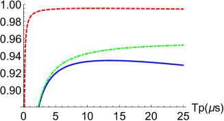
The Nd electron spin lifetime is quite long in Nd:YSO it was measured at ms Wolfowicz et al. (2015), giving ample time for the read-out process before the excitation in decays. The Nd electron spin coherence time is shorter at s at 5K Wolfowicz et al. (2015), which gives kHz. At low temperatures, similar values should be possible for Nd:YVO4. At the same time our pulses need to be long enough to fit into the limited bandwidth of the resonant response from Eq.(8), MHz, so we have to make a compromise in pulse duration. We plot the fidelity as a function of in Fig.3, here showing that pulses of length s are ideal. Then Eq.(30) gives a maximum fidelity of %. At sub-Kelvin temperatures the spin coherence time can be an order of magnitude higher Hz, which improves the fidelity to % as shown in Fig.3.
We also need to make sure the chance of false positives given by Eq.(18) is very low. For Nd:YVO4 the detuning is large, the width of the ion is small, but both transitions are equally allowed so . These combine to give a probability that is quite low at and can safely be neglected.
There is no reason that cavities can not be improved to reach higher quality factors, in Zhong et al. (2016) the theoretically possible quality factor is with the same mode volume . Then MHz and the cavity-photon coupling is still MHz. Then the single ion cooperativity is C = 7392. The Purcell factor would be , giving a detection efficiency of . Then with Hz ideal pulse length is 11s and the fidelity would be , as shown in Fig.3.
VII Conclusion
We have demonstrated that a CPHASE gate between a single photon and a rare-earth doped ion coupled to a photonic cavity is possible in the bad cavity regime. We have then shown that this gate can be used to make non-destructive measurements of a single photon. We suggested implementing a non-destructive photon measurement in Nd:YVO4 and calculated the expected fidelity, concluding that high fidelities are within reach of current technology. A fidelity of 95.3% is currently possible, and a theoretical maximum fidelity of 99.5% could be achieved. Our results show that photonic crystal cavities coupled to individual rare-earth ions are a promising platform for implementing non-destructive photon detection in solid-state systems.
VIII Acknowledgments
This work was supported by NSERC (Canada). AF and TZ acknowledge support from National Science Foundation CAREER award 1454607. We thank Dr. John Bartolomew for useful discussion.
References
- Sangouard et al. (2011) N. Sangouard, C. Simon, H. De Riedmatten, and N. Gisin, Rev. Mod. Phys. 83, 33 (2011).
- Boone et al. (2015) K. Boone, J.-P. Bourgoin, E. Meyer-Scott, K. Heshami, T. Jennewein, and C. Simon, Phys. Rev. A 91, 052325 (2015).
- Knill et al. (2000) E. Knill, R. Laflamme, and G. J. Milburn, Nature 409, 46 (2000).
- Humphreys et al. (2013) P. C. Humphreys, B. J. Metcalf, J. B. Spring, M. Moore, X.-M. Jin, M. Barbieri, W. S. Kolthammer, and I. A. Walmsley, Phys. Rev. Lett. 111, 150501 (2013).
- O’Brien et al. (2003) J. O’Brien, G. Pryde, A. White, T. Ralph, and D. Branning, Nature 426, 264 (2003).
- Turchette et al. (1998) Q. A. Turchette, N. P. Georgiades, C. J. Hood, H. J. Kimble, and A. S. Parkins, Phys. Rev. A 58, 4056 (1998).
- Duan and Kimble (2004) L.-M. Duan and H. J. Kimble, Phys. Rev. Lett. 92, 127902 (2004).
- Reiserer et al. (2013) A. Reiserer, S. Ritter, and G. Rempe, Science 342, 1349 (2013).
- Reiserer et al. (2014) A. Reiserer, N. Kalb, G. Rempe, and S. Ritter, Nature 508, 237 (2014).
- Kalb et al. (2015) N. Kalb, A. Reiserer, S. Ritter, and G. Rempe, Phys. Rev. Lett. 114, 220501 (2015).
- Hacker et al. (2016) B. Hacker, S. Welte, G. Rempe, and S. Ritter, arXiv: 1605.05261 (2016).
- Lauritzen et al. (2010) B. Lauritzen, J. Miná, H. de Riedmatten, M. Afzelius, N. Sangouard, C. Simon, and N. Gisin, Phys. Rev. Lett. 104, 080502 (2010).
- Afzelius et al. (2010a) M. Afzelius, I. Usmani, A. Amari, B. Lauritzen, A. Walther, C. Simon, N. Sangouard, J. Miná, H. de Riedmatten, N. Gisin, and S. Kröll, Phys. Rev. Lett. 104, 040503 (2010a).
- Hedges et al. (2010) M. P. Hedges, J. J. Longdell, Y. Li, and M. J. Sellars, Nature 465, 1052 (2010).
- Wesenberg et al. (2007) J. H. Wesenberg, K. Mølmer, L. Rippe, and S. Kröll, Phys. Rev. A 75, 012304 (2007).
- Sinclair et al. (2015) N. Sinclair, K. Heshami, C. Deshmukh, D. Oblak, C. Simon, and W. Tittel, arXiv: 1510.01164 (2015).
- Kolesov et al. (2012) R. Kolesov, K. Xia, R. Reuter, R. Stöhr, A. Zappe, J. Meijer, P. Hemmer, and J. Wratchtrup, Nat. Comm. 3, 1029 (2012).
- Yin et al. (2013) C. Yin, M. Rancie, G. G. de Boo, N. Stavrias, J. C. McCallum, M. J. Sellars, and S. Rogge, Nature 497, 91 (2013).
- Ahlefeldt et al. (2013) R. L. Ahlefeldt, D. L. McAuslan, J. J. Longdell, N. B. Manson, and M. J. Sellars, Phys. Rev. Lett. 111, 240501 (2013).
- Utikal et al. (2014) T. Utikal, E. Eichhammer, L. Petersen, A. Renn, S. Götzinger, and V. Sandoghdar, Nat. Comm. 5, 3627 (2014).
- Eichhammer et al. (2015) E. Eichhammer, T. Utikal, S. Götzinger, and V. Sandoghdar, N. Jour. Phys. 17, 083018 (2015).
- Kolesov et al. (2013) R. Kolesov, K. Xia, R. Reuter, M. Jamali, R. Stöhr, T. Inal, P. Siyushev, and J. Wrachtrup, Phys. Rev. Lett. 111, 120502 (2013).
- Zhong et al. (2015) T. Zhong, J. M. Kindem, E. Miyazono, and A. Faraon, Nat. Comm. 6, 8206 (2015).
- Zhong et al. (2016) T. Zhong, J. Rochman, J. Kindem, E. Miyazono, and A. Faraon, Opt. Exp. 24, 536 (2016).
- McAuslan et al. (2011) D. L. McAuslan, D. Korystov, and J. J. Longdell, Phys. Rev. A 83, 063847 (2011).
- Anisimov and Kocharovskaya (2008) P. Anisimov and O. Kocharovskaya, J. Mod. Opt. 55, 3159 (2008).
- O’Brien et al. (2011) C. O’Brien, P. M. Anisimov, Y. Rostovtsev, and O. Kocharovskaya, Physical Review A 84, 063835 (2011).
- Rippe et al. (2005) L. Rippe, M. Nilsson, S. Kröll, R. Klieber, and D. Suter, Phys. Rev. A 71, 062328 (2005).
- Afzelius et al. (2010b) M. Afzelius, M. U. Staudt, H. de Riedmatten, N. Gisin, O. Guillot-Noël, P. Goldner, R. Marino, P. Porcher, E. Cavalli, and M. Bettinelli, Journal of Luminescence 130, 1566 (2010b), special Issue based on the Proceedings of the Tenth International Meeting on Hole Burning, Single Molecule, and Related Spectroscopies: Science and Applications (HBSM 2009) - Issue dedicated to Ivan Lorgere and Oliver Guillot-Noel.
- Sun and Waks (2016) S. Sun and E. Waks, arXiv: 1602.04367 (2016).
- Siyushev et al. (2014) P. Siyushev, K. Xia, R. Reuter, M. Jamali, N. Zhao, N. Yang, C. Duan, N. Kukharchyk, A. Wieck, R. Kolesov, and J. Wratchtrup, Nat. Comm. 5, 3895 (2014).
- Probst et al. (2014) S. Probst, N. Kukharchyk, H. Rotzinger, A. Tkalec, S. Wünsch, A. D. Wieck, M. Siegel, A. V. Ustinov, and P. A. Bushev, Applied Physics Letters 105, 162404 (2014).
- Thiel et al. (2011) C. Thiel, T. Böttger, and R. L. Cone, J. Luminescence 131, 353 (2011).
- Wolfowicz et al. (2015) G. Wolfowicz, H. Maier-Flaig, R. Marino, A. Ferrier, H. Vezin, J. J. L. Morton, and P. Goldner, Phys. Rev. Lett. 114, 170503 (2015).