E-mail: kbrooks@stsci.edu
Polarization dOTF: on-sky focal plane wavefront sensing
Abstract
The differential Optical Transfer Function (dOTF) is a focal plane wavefront sensing method that uses a diversity in the pupil plane to generate two different focal plane images. The difference of their Fourier transforms recovers the complex amplitude of the pupil down to the spatial scale of the diversity. We produce two simultaneous PSF images with diversity using a polarizing filter at the edge of the telescope pupil, and a polarization camera to simultaneously record the two images. Here we present the first on-sky demonstration of polarization dOTF at the 1.0m South African Astronomical Observatory telescope in Sutherland, and our attempt to validate it with simultaneous Shack-Hartmann wavefront sensor images.
keywords:
wavefront sensing, polarization1 INTRODUCTION
One of the greatest challenges with ground-based observations is the perturbation of the incoming wavefronts through the turbulent atmosphere. We approximate light from a distant object as a succession of plane parallel flat wavefronts, but by the time the starlight reaches the ground, it is no longer flat. If we are able to measure the atmospheric aberrations through wavefront sensing, it is possible to correct for them using an adaptive optics system or through post-processing of the point spread function (PSF).
The Optical Transfer Function (OTF) can be used to measure the image quality of an optical system, defined as the Fourier transform of the amplitude squared of a point source, to that of the image in frequency space ([1]). Using the definition of the OTF, [2, 3] it was shown[4] that taking the difference of the OTFs of two pupils with an amplitude or phase perturbation can return information about the identical regions of the pupils, notably the complex amplitude of the electrical field in the pupil. In order to reconstruct this phase, the two images of the complex pupils must be taken in quick succession, during which time the phase must be expected not to change so that the only difference measured is the modification made to the pupil. Given the rapid temporal evolution of the atmosphere, it is impractical to image two different pupils so quickly as to image the phase of the atmospheric wavefront before it changes, without also being affected by any vibrations in the system.
Using polarization for dOTF was first explored using a polarization finger in the pupil plane and a polarized beamsplitter to split the light into two different polarization orientations [2]. This method, however, was rejected due to the introduction of both fixed and temporal non-common-path errors that are impractical to remove. Instead, we use a camera with a pixel-matched micropolarizer array to perform dOTF without any common path errors and without the need for a centrated star. We carry out first on-sky observations with a polarization camera and a Shack-Hartmann sensor to validate the reconstructed atmospheric phase. This method, which we call polarization dOTF, is still limited by PSF saturation and signal-to-noise on the detector.
We show through on-sky testing that this method produces a measure of diversity and we analyze the data we have obtained. Due to camera timing issues, we were not able to validate the polarization dOTF method with the Shack-Hartmann wavefront sensor.
2 Polarization dOTF
The image-based differential Optical Transfer Function wavefront sensing (dOTF WFS) method was first introduced [2, 4, 3] as a supplement to current wavefront sensing methods. This method requires the imaging of two similar pupils, where one pupil is modified. The Fourier transform of each PSF produced by the pupils give their respective OTFs, which are then subtracted from one another. The resultant image is of two overlapping, complex conjugates of the initial pupils, reflected about the area where they are different (see Figure 1). Any part of these pupils not in the overlap region is the complex conjugate of the original complex pupil plane[3] which is a consequence of taking the Fourier transform of the PSF. This unique property allows us to split the dOTF image into both amplitude and phase, where the phase is the phase of the wavefront at the time of observation. To retain the maximum amount of information about the original amplitude and phase, the modification is placed at the edge of the pupil, minimizing the loss of information in the overlap region.
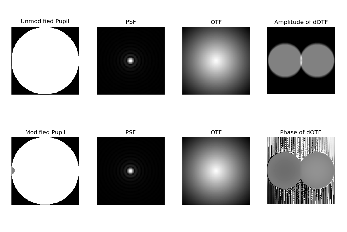
While all previous iterations of dOTF WFS (where images are taken in quick succession) provide good diagnostics on the method, in order to be sure that we are imaging the same phase of the wavefront for each pupil, simultaneous imaging needs to occur, something that can be achieved with polarization dOTF.
2.0.1 Using polarization
Light is a transverse electromagnetic wave that can be decomposed into two orthogonal polarizations. The direction or angle of polarization is often described by the Stokes vector [I,Q,U,V]T. Here we focus only on the linear polarization: Q, the horizontally and vertically polarized light, and U, the diagonally polarized light.
We explore a detector that can register two orthogonal directions of linear polarization simultaneously (+Q and -Q, or +U and -U). By using a linearly polarized modification in the pupil plane that is aligned with one of the measurable directions, we can retrieve two images - one for each polarization orientation - given that two orthogonally orientated polarizing sheets block out all light, and parallel orientated polarizing sheets allows all light to pass. While this removes many of the previously presented challenges with the dOTF method for WFS, polarization dOTF WFS is still limited by PSF saturation and low signal to noise.
3 Observations
During 2015 June 03 to 09 UT, we observed at the South African Astronomical Observatory (SAAO) in Sutherland, South Africa. During these six nights of observation, we tested our Polarization Camera alongside a Shack-Hartmann Wavefront Sensor (SHWFS) within a custom built cage mount.
3.1 Site
The SAAO Sutherland site is located at an altitude of 1798m, approximately 375km outside of Cape Town in South Africa. This site is home to the Southern Africa Large Telescope (SALT) and several other telescopes of varying size. The optical turbulence at the Sutherland site [5] from the surface to an altitude of 1km above the surface at this site has a median seeing of 1.32”, accounting for 84% of the turbulence. The other 16% comes from the atmosphere above 1km with a median seeing of 0.41”.
3.2 Instrument Setup
At the SAAO Sutherland site, we used the 1m Cassegrain reflector, adding our instrument to the back of the telescope as seen in Figure 2. In order to simultaneously measure the wavefront with the SHWFS and the polarization camera, we used a 50% beamsplitter to feed light to both wavefront sensors simultaneously.
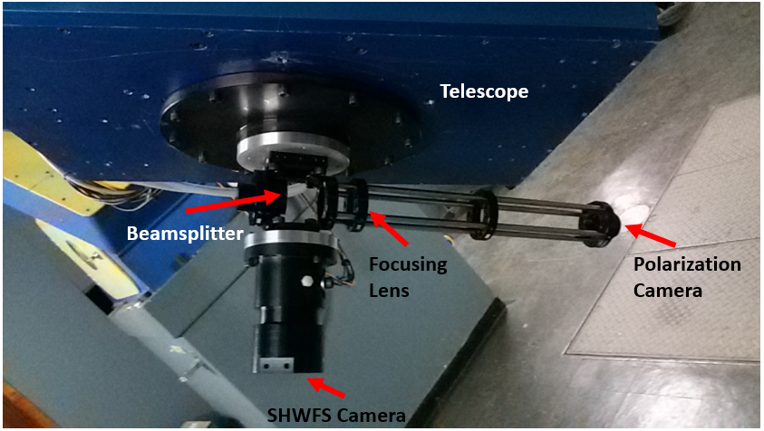
Given simultaneous imaging on two detectors, the instrument included a beamsplitter that sent half of the light to the SHWFS (mounted directly behind the telescope) and the other half to the polarization camera. In the pupil of the telescope we taped a circular polarization sheet, 10cm in diameter, to act as our obscuration, and aligned it with respect to one of the pixels in the polarization camera.
The camera used for these tests is a 4DTechnology PolarCamTM, pixelated polarizer-based CCD[6]. This camera is unique in its ability to image in four different polarization angles simultaneously. This is possible through the use of a pixelated micropolarizer array which is matched to the pixels on the detector. This polarizer array is made up of many “super pixels”, where one super pixel includes four pixels, each with a different linear polarization orientation (+Q, -Q, +U, -U). By mounting the micropolarizer array directly onto the CCD and adding a border around each polarizing element, polarization crosstalk is limited. At 550nm, the maximum transmission of the pixelated polarizer is 80% of the total amount of light that is polarized in that direction[6]. See Table 1 for additional specifications for this camera. An optical cage system was used to mount the optical components for the polarization dOTF WFS, including the beamsplitter, a focusing lens, and the polarization camera, attached to the end of the optics cage (seen to the right in Figure 2).
| Description | PolarCam Polarization Camera |
|---|---|
| Acquisition Mode | Simultaneous polarization imaging |
| Sensor Type | Monochrome interline transfer CCD |
| Spectral Range | 320 nm - 1060 nm |
| Pixel Size | 7.4 m |
| Bit Depth | 12-bit |
| Interface | GigE Ethernet |
| Camera Speed | 114 fps (maximum) |
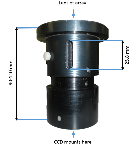
The SHWFS used for observation was assembled such that the light was first sent through a collimating lens and then to the camera on which there is a lenslet array forming a Shack-Hartmann WFS. A schematic of this system can be seen in Figure 3, showing that the collimating lens sits near the top of the system (in the figure), below which there is a nested cylinder that can be extended by up to 20mm. The detector is mounted to the bottom of this system which was then attached below the beamsplitter, as seen in Figure 2.
3.2.1 Polarization Obscuration Alignment
In order for polarization dOTF to work properly, the obscuration at the telescope pupil must have its angle of polarization aligned with one of the four polarization angles in each super pixel of the camera. If the polarization angle of the camera is, for example, aligned with the +Q and -Q orientations, then we can use those pixels on the detector. The same goes for the +U and -U orientations.
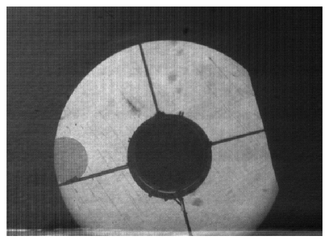
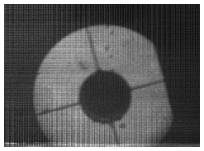
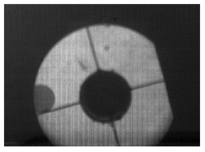
Imaging the pupil plane with the polarization finger in position and aligned with the camera, we see that of the light is lost at the location of this obscuration (see Figure 4, left). In order to align the camera and the polarization finger, a secondary polarization finger was made that could be placed directly in front of the camera and rotated until uniform intensity is reached (half the intensity of the original image, middle image) across the pupil plane, or zero throughput (Figure 4, right) at the point at which the polarization obscuration sits in the pupil plane.
3.3 Observation Overview
Due to the setup of our system, splitting the light between the SHWFS and the polarization camera, it was necessary to observe stars brighter than 2nd magnitude. In a rough estimate of the loss of light through the elements in the telescope and our instrument (as outline in Table 2), we can only expect a throughput of . Additionally, we are limited in our selection of objects to single-star systems, since the lenslets of the SHWFS make it difficult to extract phase information from a binary system unless the stars have a sufficiently large separation. An exception for one binary system (Antares) was made due to brightness limitations.
| Optical Component | Transmission |
|---|---|
| Atmosphere | 80% |
| Primary Mirror | 60% |
| Secondary Mirror | 60% |
| Beamsplitter | 50% |
| Detector Quantum Efficiency | 60% |
| Polarization | 40% |
| Percent of light remaining | 3.456% |
We have two nights of usable observations, during which we observed several bright objects with exposure times between 10 and 30ms to try to match the timescale on which the atmosphere changes. Simultaneously, we collected seeing measurements from the Multi Aperture Scintillation Sensor - Differential Imaging Motion Monitor (MASS-DIMM) device at the Sutherland site. The seeing varied from 1.0-1.2” on 7 June and 1.4-1.5” on 8 June.
4 Analysis
4.1 Modelling: What we expect
To get an idea of what to expect, we simulate dOTF wavefront sensing based on the conditions of the 1m telescope at the SAAO Sutherland site.
For our simulations, we use a pupil mask that mimics the pupil of the 1m telescope with a secondary mirror supported by four beams. To the pupil we add an obscuration of varying sizes, at 50% intensity to imitate a polarized obscuration.
Choosing the optimum size of the obscuration is based on the balance between the effects of photon shot noise, integration time, and spatial resolution. A small obscuration will return more of the higher order structure of the phase in the pupil plane, however, it requires a longer integration time in order to get enough signal to overpower the photon shot noise, and integration time should not exceed the coherence time of the atmosphere in order to properly image the changing wavefronts. A large obscuration can result in a loss of spatial resolution since the variations in the phase become smeared out. Additionally, the size of the overlap region corresponds to the size of the obscuration disk and in this region, the phase map will not be reconstructed, resulting in an even greater loss in phase information for larger obscurations. Through our simulations, we can explore this balance in parameter space (as done in Figure 5) and compare this to the results of our on-sky testing.
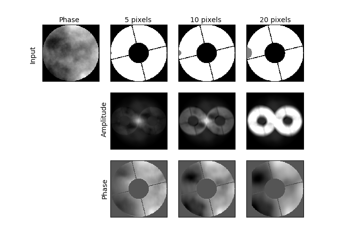
In the upper left corner of the top figure in Figure 5, we show the phase applied to the initial complex pupil plane. Here we use a Kolmogorov phase screen, based on the Kolmogorov model of atmospheric turbulence, which seeks to model the random motions of atmospheric turbulence by looking at motion in a fluid medium[7]. We also add a Gaussian noise distribution to the PSF and reduce the PSF flux by 1,000 in order to model a non-ideal case. To the right of the phase map in Figure 5, we show the three different obscuration sizes in the expected telescope pupil - radius = 5, 10, and 20 pixels, for an aperture of D = 200 pixels - where half of the obscuration can be seen on the left side of the pupil. For each combination of telescope pupil and obscuration size, using the indicated phase map, we find the dOTF reconstructed amplitude(second row) and phase(third row).
As was indicated in Figure 1, the dOTF reconstructed phase includes a large amount of noise as a result of the Fourier transform, so as to clearly seen how the dOTF reconstructs the phase, we mask one of the circles and orient it to match the input phase. We also mask the secondary, secondary supports, and the overlap region in the pupil plane as there is no information about the phase retained in these regions.
In the amplitude of the dOTF image (Figure 5, second row) the simulations show us that in the presence of noise, a one pixel obscuration will result in a dOTF reconstructed image dominated by noise, and we easily see that there is much more diversity with the large obscuration. In the masked phase (Figure 5, third row) we see that the phase is poorly reconstructed with small obscurations, while the use of larger obscurations tends toward better reconstruction results.
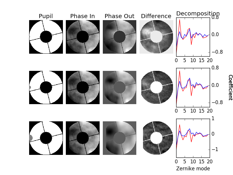
Moving one step forward to see how well we can reconstruct the phase, we turn to the Zernike decomposition of our input and output (reconstructed) phase given the convolution with the pupil. This can tell us which Zernike modes are most difficult for this method of wavefront sensing to reconstruct Figure 6 shows the input pupil with the different sizes of obscurations, the input phase masked with the pupil, the dOTF reconstructed phase, the difference between the second and third columns, and the decomposition of the second (in blue) and third (in red) columns into their Zernike coefficients. The last column clearly shows where the reconstruction of the phase struggles (the regions where the red and blue lines diverge). The modes where such divergence is prominent, correspond with regions where the phase is masked (i.e. the center of the reconstruction). As a result, we maintain that we expect the regions where the pupil remains unmasked, the dOTF reconstruction of the phase, even for larger obscurations, is able to retain a large amount of the phase structure.
5 Results
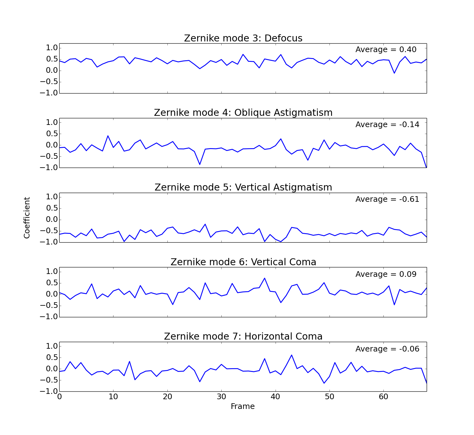
With the reduced data from the observations split into the different polarization orientations, we are able to perform dOTF on the data for the +Q and -Q orientations. We can expect to recreate the phase of the wavefront at that moment and create a movie of how the phase of the wavefront changes during the moments of observation. We expect that the variety of stars, exposure times, and filters, will give us limits on the dOTF method. Unfortunately, instead we find that for most observations, there is not enough signal from the star to fully reconstruct the phase. We show in Figure 7 one of the exposures of Antares with an exposure time of 30ms and no filter, with the amplitude, and the masked phase the dOTF reconstruction. The reconstruction appears to be heavily influenced by noise and we do not see the expected diversity given the size of the obscuration. Even when looking through a movie of the reconstructed amplitude and phase for all frames during the observation of Antares, we see a change in the signal and reconstructed phase, however patterns moving across the pupil plane do not emerge as expected. We attempt to further discern these patterns by breaking down each frame into several Zernike modes (as seen in Figure 8) and seeing how the coefficients of those modes evolve with time. Smooth trends would emerge if the signal were not dominated by noise, but as is clearly seen in Figure 8, there are no trends to follow.

Using the Kolmogorov phase screen (Figure 5), we see that by adding noise and reducing the flux, for obscuration radii of 1 or 5 pixels, the dOTF reconstructed amplitude was dominated by noise and takes on a similar shape to our dOTF reconstructed amplitude data. With obscuration radii on the same order as the one used on-sky (1/10 of the aperture), the simulations showed more signal in the output.
5.1 Camera Performance
We found that the micropolarizer array was seamless with no measured polarization crosstalk. Additionally, we had no problems with the polarization of the light. The light lost due to polarization does play a significant role, but can be overlooked if the overall performance is good. We assume that there might also be some issues with the gain measurement for the camera but, have not yet explored this further.
Unfortunately, we had a large number of dropped frames over the course of our observations, where we lost as many as 10 frames in approximately ten seconds of exposures. The camera never achieved the expected frame rate, however it is difficult to quantify this given the precision of the time stamps. The software does not have the ability to set a time frame over which to take images, only a start and stop function. These factors make it difficult to know how much data is being taken, especially if frames are dropped during observations.
5.2 Comparison with SHWFS
In comparing the dOTF phase reconstructions with the data from the SHWFS, we now face the following complications: not enough signal in the dOTF output -making the reconstruction difficult to trust and therefore hard to compare- and the best signal (Antares) is a binary system.
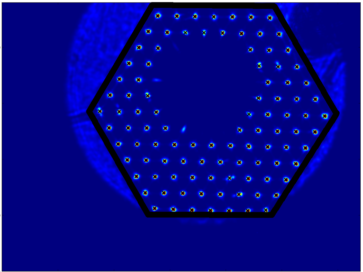
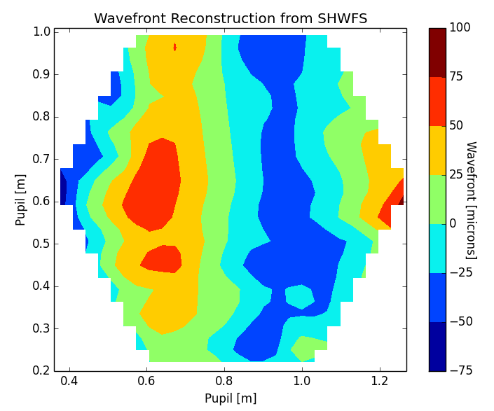
Figure 9 shows one frame of Antares taken by the SHWFS on the left and the reconstructed wavefront on the right. The hexagon we see marks the edges of the area in the pupil that the SHWFS can reconstruct. It is only within this hexagonal area that we can compare our data. We know that the comparison of these data is limited by a time and spatial offset. It is seen in figure on the left in Figure 9 that the orientation of the pupil for the SHWFS is different than what we see with our polarization camera (this is obvious by the location of the polarization finger in the upper right of this figure if compared to Figure 4). In the figure on the right in Figure 9 we give an example of the wavefront reconstruction from the SHWFS for Antares.
As for the time offset, we know that the images taken by the Shack-Hartmann system were taken at around the same time as the polarization camera images, however since the time stamps for both data are precise only to within one second (while the exposures are on the order of milliseconds), we could not determine a more precise offset. Lastly, given the performance of the polarization camera, we can assume that there are some significant time gaps in the dOTF data which we could not recover from our observing logs. Due to these complications, we are unable to directly compare the outputs of the SHWFS and the polarization dOTF WFS.
6 Conclusions
We show that using a polarization finger to provide pupil diversity works and that we can detect a change in the phase of the wavefront. However, we are unable to confirm that the dOTF is accurately reconstructing the incoming wavefront at the telescope. The two reasons for this are: (i) the lower than expected signal to noise of the camera on bright stars and (ii) intermittent and unexplained frame drops from the polarization camera preventing wavefront synchronization between the two wavefront sensors. Future work includes investigating the polarization camera drivers to make them more robust and optimizing the optical design to increase the throughput of the instrument.
Acknowledgements.
This paper uses observations made at the South African Astronomical Observatory (SAAO). We thank the NWO and NRF for support of the project. We would like to thank the mechanics and the workshop at the SAAO for making the instrument mounting plates on very short notice.References
- [1] Williams, C. S. and Becklund, O. A., [Introduction to the Optical Transfer Function ], vol. 112, SPIE Press (2002).
- [2] Codona, J. L., “Theory and application of differential OTF (dOTF) wavefront sensing,” in [Proc. SPIE ], Society of Photo-Optical Instrumentation Engineers (SPIE) Conference Series 8447, 6 (July 2012).
- [3] Codona, J. L., “Differential OTF Wavefront Sensing,” Optical Engineering 52, 097105 (Sept. 2013).
- [4] Codona, J. L. and Doble, N., “Experimental evaluation of differential OTF (dOTF) wavefront sensing,” in [Proc. SPIE ], Society of Photo-Optical Instrumentation Engineers (SPIE) Conference Series 8447, 6 (July 2012).
- [5] Catala, L., Crawford, S. M., Buckley, D. A. H., Pickering, T. E., Wilson, R. W., Butterley, T., Shepherd, H. W., Marang, F., Matshaya, P., and Fourie, C., “Optical turbulence characterization at the SAAO Sutherland site,” MNRAS 436, 590–603 (Nov. 2013).
- [6] Brock, N. J., Kimbrough, B. T., and Millerd, J. E., “A pixelated micropolarizer-based camera for instantaneous interferometric measurements,” in [Proc. SPIE ], Polarization Science and Remote Sensing V, 8160W 8160 (Sept. 2011).
- [7] Hardy, J. W., [Adaptive Optics for Astronomical Telescopes ], Oxford University Press (1998).