3D Single-port Labyrinthine Acoustic Metamaterial
Abstract
In this paper, we report on the design, fabrication, and experimental characterization of a 3D single-port labyrinthine acoustic metamaterial. By using curled perforations with one end closed and with appropriate loss inside, the proposed metamaterial can perfectly absorb airborne sounds in a low frequency band. Both the position and width of the band can be tuned flexibly. A tradeoff is uncovered between the relative absorption bandwidth and thickness of the metamaterial. When the relative absorption bandwidth is as high as , the requirement of deep subwavelength thickness () can still be satisfied.
pacs:
43.20.+g, 43.58.+z, 46.40.CdAcoustic metamaterials (AMMs) are artificial periodic structures with subwavelength building blocks that exhibit unusual acoustic characteristics Liu ; Li1 ; Lai ; Fang ; Hu ; Yang1 ; Mei ; Yang2 ; Ma . There has been tremendous attention in AMMs since its first demonstration in 2000 by Liu et al Liu . An amount of functionalities and applications have been proposed and achieved based on AMMs Li2 ; Zhu ; Park ; Lu ; Chr2 ; Fle ; Cum ; Chen ; Zhang . Labyrinthine AMMs (LAMMs) composed of curled perforations are one of the most significant types of AMMs due to their extreme constitutive parameters and plentiful potential applications Liang1 ; Xie1 ; Liang2 ; Xie2 ; Cheng . For instance, LAMMs show diverse properties such as double negativity, a density near zero, and a large refractive index in different frequencies, giving rise to fascinating phenomena including negative refraction and zero-density tunneling Liang1 ; Xie1 ; Liang2 . By applying a graded structures, a labyrinthine metasurface with graded index can be constructed to modify the wavefront and direction of outgoing waves Xie2 . Total reflection of low-frequency sounds has also been achieved very recently by applying an ultrasparse labyrinthine metasurface Cheng . By now, most of previous LAMMs have a two-port character so that transmission is permitted and absorption can be reasonably neglected. In addition, the studies have been mainly done in 2D cases. Although they are important to fully control sound waves in 3D space, 3D LAMMs have seldom been investigated and demonstrated.
In this paper, we report on the design, fabrication, and experimental characterization of 3D single-port LAMMs that are composed of curled, one-end-closed channels. Via adjusting the sound loss in channels to a critical value, such LAMMs can have impedance matching to background and thus perfectly absorb sounds in a low frequency band; both the position and width of the band can be tuned flexibly. Analytic formulas are derived to predict the critical loss in channels and relative absorption bandwidth, and their accuracy are verified by both simulations and experiments. A tradeoff is uncovered between the relative absorption bandwidth and thickness of the LAMM. When the relative absorption bandwidth is as high as , the requirement of deep subwavelength thickness () can still be satisfied.
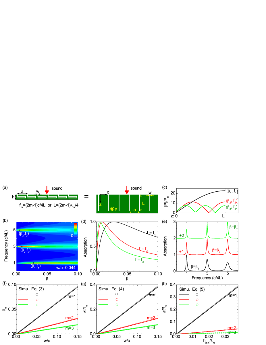
To illustrate the principle, we first consider a 2D-labyrinthine acoustic metasurface, which is a rigid slab with a channel array embedded [see Fig. 1(a)]. Unlike previous labyrinthine AMMs Liang1 ; Xie1 ; Liang2 ; Xie2 ; Cheng , the labyrinthine metasurface here employs one-end-closed channels so that transmission is forbidden. The metasurface is perpendicular to the direction, invariant along the direction, and immersed in a background fluid where the sound velocity is . The channels have a length of , width of , and period along the direction (). Upon the metasurface is normally impinging a harmonic sound plane wave with wavelength and frequency . Inside the channels, the wavenumber of sound , where and denotes the loss of sound. The system can be dealt with a coupled mode theory Supp . If only fundamental modes are considered in both the channels and background, the absorption of the metasurface can be analytically derived Supp ,
| (1) |
where the reflection coefficient , the impedance of the metasurface relative to the background , and is the imaginary unity. Matched impedance () and thus unity absorption () can be achieved when particular values of frequency and loss () are satisfied. Here, the resonant frequency and critical loss are given by Supp
| (2) | |||||
| (3) |
where is a positive integer (). The corresponding relative absorption bandwidth can also be analytically obtained
| (4) |
where is the full width of half maximum for the -th order absorption peak Supp . When the rigid body has a minimal filling fraction in the metasurface, the metasurface has a minimal thickness , so that Eq. (4) can be rewritten as
| (5) |
where is the wavelength of the -th order resonance. We note that, if the ratio of is replaced by (with , , and defined in Figs. 2(a)-2(c)), the above formulas are also valid for a 3D-labyrinthine metasurface. In particular, to achieve perfect absorption for the fundamental mode () in 3D, the loss in channels should satisfy
| (6) |
To verify the accuracy of the above formulas, we did full-wave simulations for a 2D-labyrinthine metasurface with parameters of and length . The results are shown in Figs. 1(b)-1(e). We can see that the metasurface supports multiple resonant modes with frequencies agreeing well with Eq. (2). For the -th order resonance [see Fig. 1(c)], there are nodes (with local minimum) of sound pressure along the channel, which are also antinodes (with local maximum) of fluid velocity. Due to the friction between the fluid and channel walls, sound waves dissipate inside the channels. However, only when the sound loss inside channel approaches critical values (), the metasurface can absorb totally sound waves at resonant frequencies (), as shown in Figs. 2(d) and 2(e).
Figs. 1(f)-1(h) demonstrate the critical loss inside channels and relative absorption bandwidths for different channel widths. Good agreement is found between the simulated and analytical results. Both the critical loss and relative absorption bandwidths are independent of the channel length, and related only to both the resonance order and relative channel width . If a small resonance order (implying few antinodes of fluid velocity) or large channel width is applied, a high critical loss is needed for achieving total absorption, leading to a large relative absorption bandwidth.
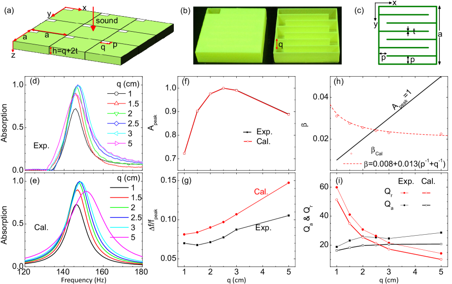
According to the above theory, we fabricated a 3D-labyrinthine metasurface which is periodic in the - plane and embedded in air, as shown in Fig. 2(a). Its building block is a cuboid box fabricated with polylactic acid (PLA) by means of 3D printing technology [see Fig. 2(b)]. The box has a fixed size of cm in both the and direction and a height of in the direction. A curled channel is embedded inside the box [see Fig. 2(c)] and connected to outside via an aperture at the upper surface of the box. Both the opening and cross section of channel are rectangles with the same width of cm and height of , where the thickness mm for all the walls of the box and channels.
In order to adjust the sound loss in channels, we fabricated a series of building blocks with the channel height ranging from 1 cm to 5 cm, and measured their acoustic absorption spectra [see Fig. 2(d)]. Absorption peaks can be seen at 146 Hz, corresponding to the resonance of a channel with length of cm. Such an effective channel length is close to the realistic length of cm. The channel height has small influence on the resonant frequency while it strongly affects the amplitude of absorption peak [see Fig. 2(f)]. When the channel height increases, the peak amplitude increases first and then decreases. When the channel height cm, the measured absorption can be as high as 99.9% at resonant frequency. In addition, the relative absorption peak width increases with increasing the channel height (or the metasurface thickness). For a channel height of 3 cm, the relative peak width can be 9%, which is about ten times of membrane-type metasurfaces Ma .
We applied a finite-element method to simulate the 3D-labyrinthine metasurface Supp . The fundamental resonant frequency was first obtained by using a small sound loss in channels. Then the critical loss in channels was searched for achieving unity absorption at the resonant frequency, as shown as the solid line in Fig. 2(h). The simulated results are very close to the values by Eq. (6). The sound loss in channels was also obtained [see the symbols in Fig. 2(h)] by fitting the amplitudes of calculated absorption peaks with the measured ones. We can see that the sound loss in channels decrease with increasing the channel height . The obtained sound loss from measured absorption can be fitted by a simple model
| (7) |
where is the sound loss in fluid without boundaries, and the second term with is due to the friction between fluid (air) molecules and channel walls. When the channel height cm, the loss in channels approaches a critical value, leading to unity absorption at resonant frequency [see Figs. 2(e) and 2(f)]. The relative peak width is also found to increase with increasing the channel height [see Fig. 2(g)].
Apart from the above first-principle microscopic simulation, the labyrinthine metasurface can also be understood by a macroscopic model, where the metasurface is regarded as a one-port resonator array with reflection coefficient given by
| (8) |
Here, and are the absorptive and radiative quality factors, respectively; and are the lifetimes of the resonance due to absorption inside the structure and radiation to the far field, respectively. For the mode, the absorptive and radiative quality factors, and , were retrieved from the measured and simulated absorption Supp , as shown in Fig. 2(i). We can see that, with increasing the channel height , the absorptive quality factor increases while the radiative one decreases. When cm cm, the two quality factors are close to each other (), so that the metasurface can absorb strongly () incident sounds from the background medium of air at resonant frequency.
The above experiments demonstrate that, when appropriate cross sections of channels are adopted, a labyrinthine metasurface with deep-subwavelength thickness () can totally absorb sounds at resonant frequency of Hz, holding a relative bandwidth of 9%. In the following, we show that the relative absorption bandwidth can be further broadened by applying various channels in the unit cell of metasurface.
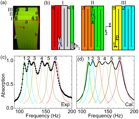
Figure 3(a) shows a fabricated cuboid unit cell with an unchanged size cm in both the and directions and increased height cm in the direction. Inside the unit cell, there exist six channels with the same cross section ( cm and cm; see Fig. 3(b)). The channel lengths are , , , , , and cm, respectively.
Absorption spectra were first measured for unit cells with a single channel [see Fig. 3(c)], where one channel is hollow and the others were filled with water. We can see that the six channels individually contribute six absorption peaks, with central frequencies at 109, 118, 128, 144, 157 and 171 Hz, respectively. Similar to the channel lengths, the six resonant frequencies are also a geometric progression with common ratio of . All the six absorption peaks have amplitudes higher than 97% and an average width about 9%. When all the six channels are unblocked, the six peaks can merge together into an absorption band, with frequencies ranging from 105 to 177 Hz and relative width of 51%. The thickness of the unit cell is much shorter than the central wavelength of the absorption band ().
Although only six channels exist in the unit cell as shown in Fig. 3(a), more channels can be adopted in the configuration. For an extreme situation with 21 channels, the first-order absorption band can possess a relative bandwidth as high as 180%. In addition, absorption bands with neighbored orders can overlap with each other, resulting in an ultrabroad absorption band ( for ) which is similar to that of a porous medium Are . Hence, our 3D single-port LAMMs serve as a bridge linking damping resonant structures in a narrow band Ma ; Maa and porous absorptive media for high frequencies Are .
In summary, we have designed, fabricated, and tested a 3D single-port LAMM which can perfectly absorb airborne sound in a low-frequency band. Both the position and width of the band can be tuned flexibly. Such a new type of sound-absorbing materials serves as a bridge between traditional porous materials for high frequencies and advanced damping resonant structures in a narrow band. Our work presents a robust approach in controlling the sound loss in perforations and could benefit experimental realizations of more acoustic designs based on labyrinthine metamaterials.
References
- (1) Z. Y. Liu, X. Zhang, Y. Mao, Y. Y. Zhu, Z. Yang, C. T. Chan, P. Sheng, Science 289, 1734 (2000).
- (2) J. Li and C. T. Chan, Phys. Rev. E 70, 055602 (2004).
- (3) Y. Lai, Y. Wu, P. Sheng, and Z. Q. Zhang, Nature Mater. 10, 620 (2011).
- (4) N. Fang, D. Xi, J. Xu, M. Ambati, W. Srituravanich, C. Sun, and X. Zhang, Nature Mater. 5, 452 (2006).
- (5) X. Hu, K. M. Ho, C. T. Chan, and J. Zi, Phys. Rev. B 77, 172301 (2008).
- (6) Z. Yang, J. Mei, M. Yang, N. H. Chan, and P. Sheng, Phys. Rev. Lett. 101, 204301 (2008).
- (7) J. Mei, G. Ma, M. Yang, Z. Yang, W. Wen, and P. Sheng, Nature Commun. 3, 756 (2012).
- (8) M. Yang, G. Ma, Z. Yang, and P. Sheng, Phys. Rev. Lett. 110, 134301 (2013).
- (9) G. Ma, M. Yang, S. Xiao, Z. Yang and P. Sheng, Nature Mater. 13, 873 (2014).
- (10) J. Li, L. Fok, X. B. Yin, G. Bartal, and X. Zhang, Nature Mater. 8, 931 (2009).
- (11) J. Zhu, J. Christensen, J. Jung, L. Martin-Moreno, X. Yin, L. Fok, X. Zhang, and F.J. Garcia-Vidal, Nature Phys. 7, 52 (2011).
- (12) C. M. Park, J. J. Park, S. H. Lee, Y. M. Seo, C. K. Kim, and S. H. Lee, Phys. Rev. Lett. 107, 194301 (2011).
- (13) M. H. Lu, X. K. Liu, L. Feng, J. Li, C. P. Huang, Y. F. Chen, Y. Y. Zhu, S. N. Zhu, and N. B. Ming, Phys. Rev. Lett. 99, 174301 (2007).
- (14) J. Christensen, L. Martin-Moreno, and F. J. Garcia-Vidal, Phys. Rev. Lett. 101, 014301 (2008).
- (15) R. Fleury and A. Alu, Phys. Rev. Lett. 111, 055501 (2013).
- (16) S. A. Cummer and D. Schurig, New J. Phys. 9, 45 (2007).
- (17) H. Chen and C. T. Chan, Appl. Phys. Lett. 91, 183518 (2007).
- (18) S. Zhang, C. Xia, and N. Fang, Phys. Rev. Lett. 106, 024301 (2011).
- (19) Z. Liang and J. Li, Phys. Rev. Lett. 108, 114301 (2012).
- (20) Y. Xie, B. I. Popa, L. Zigoneanu, and S. A. Cummer, Phys. Rev. Lett. 110, 175501 (2013).
- (21) Z. Liang, T. Feng, S. Lok, F. Liu, K. B. Ng, C. H. Chan, J. Wang, S. Han, S. Lee, and J. Li, Sci. Rep. 3, 1614 (2013).
- (22) Y. Xie, W. Wang, H. Chen, A. Konneker, B.-I. Popa, and S. A. Cummer, Nature Commun. 5, 5553 (2014).
- (23) Y. Cheng, C. Zhou, B. G. Yuan, D. J. Wu, Q. Wei, and X. J. Liu, Nature Matter. 14, 1013 (2015).
- (24) See the Supplemental Material for derivations of Eqs. (1)-(4), details of simulations, sample fabrications, and characterizations.
- (25) D-Y. Maa, J. Acoust. Soc. Am. 104, 2861 (1998).
- (26) J. P. Arenas and M. J. Crocker, J. Sound Vib. 44, 12-18 (2010).