High-rate axial-field ionization chamber for particle identification of radioactive beams
Abstract
The design, construction and performance characteristics of a simple axial-field ionization chamber suitable for identifying ions in a radioactive beam are presented. Optimized for use with low-energy radioactive beams ( 5 MeV/A) the detector presents only three 0.5 m/cm2 foils to the beam in addition to the detector gas. A fast charge sensitive amplifier (CSA) integrated into the detector design is also described. Coupling this fast CSA to the axial field ionization chamber produces an output pulse with a risetime of 60-70 ns and a fall time of 100 ns, making the detector capable of sustaining a relatively high rate. Tests with an source establish the detector energy resolution as 8 for an energy deposit of 3.5 MeV. The energy resolution with beams of 2.5 and 4.0 MeV/A 39K ions and the dependence of the energy resolution on beam intensity is measured. At an instantaneous rate of 3 x 10⁵ ions/s the energy resolution has degraded to 14% with a pileup of 12%. The good energy resolution of this detector at rates up to 3 x 10⁵ ions/s makes it an effective tool in the characterization of low-energy radioactive beams.
keywords:
ionization chamber , particle identification , radioactive beam1 Introduction
The development of radioactive isotope beams (RIBs) has enabled the investigation of nuclei away from -stability [1, 2, 3, 4], which is crucial in understanding nucleosynthesis in exotic astrophysical environments [3], as well as the structure of exotic nuclei [3, 4]. RIBs can be produced by a variety of techniques including projectile fragmentation [5], ISOL [6], and photofission [7]. As the primary nuclear reaction produces a distribution of product nuclei, to provide a useful secondary radioactive beam, it is necessary to select the nuclide of interest from this distribution. This separation is typically accomplished through electromagnetic means [8]. Often, however, this separation does not produce a pure beam, and other reaction products with similar mass-to-charge ratios contaminate the beam. An effective way to address this challenge is to identify each ion in the beam on a particle-by-particle basis. A commonly used approach to accomplish this is through measurement of the energy loss (E) and time-of-flight (TOF) of each ion [9].
The E information is often obtained from gas ionization chambers [10] used in transmission mode. The uniform thickness achieveable with these detectors, as well as their robustness against radiation damage are key factors in their utility. A common geometry of an ion chamber utilizes an electric field transverse to the incident ion direction [11], with a Frisch grid used to remove the dependence of the pulse amplitude on position. In this geometry of ion chambers, however, the drift time of the electrons in the direction transverse to the beam direction typically limits the rate to 104 ions/s. To overcome this limitation of a slow response time, an axial field design can be employed. Axial field ionization chambers have been successfully employed as E detectors for heavy-ions since the 1980’s [12, 13]. Recently, the high rate capability of this design has been exploited at both high [14] and low energies [15] by using multiple tilted electrodes in the beam path to identify reaction products in a radioactive beam. When the incident energy is sufficiently high (100 MeV/A) thin metallized foils have been utilized for the electrodes. In contrast, at low incident energies (5 MeV/A) the electrodes consist of wire harps. Both designs involve the insertion of multiple electrode planes (15-24) into the beam path, a source of considerable scattering and energy loss for the incident ion. In the subsequent sections, we describe the development and characterization of a simple high-rate axial-field ionization chamber, designated the Rare Ion Purity Detector (RIPD) which inserts a minimal amount of material into the beam path.
2 Physical Configuration
The principal motivation in developing this detector was investigation of fusion for neutron-rich light ion beams at energies near the fusion barrier [16, 17]. Due to the low energy beams utilized in these experiments, particular attention was given to the total thickness of the detector in order to minimize the beam divergence and energy straggling incurred by inserting the detector into the beam path. Prior experience established that minimizing scattering of the beam was essential. This requirement meant eliminating any wire planes in the beam path. To implement the simplest axial field geometry while minimizing the electron collection time, a central anode is used with the metallized windows serving as cathodes.
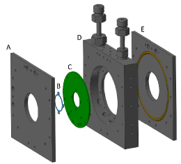
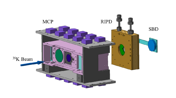
A CAD drawing of RIPD is shown in Fig. 1. The detector is comprised of an aluminum body, two stainless steel window plates, and a thin central anode foil. The anode is coupled to a charge sensitive amplifier (CSA) housed inside the aluminum body. The body measures approximately 11 cm x 11 cm transverse to the beam direction and 2.0 cm thick along the beam axis. The window plates are 5 mm thick and have a 38 mm diameter opening for the beam to pass through, over which 0.5 m aluminized mylar is epoxied. These mylar foils serve to contain the gas within the active volume and act as cathodes. The window plates are sealed to the body of the detector using O-rings. No support wires are used with these windows to minimize scattering of the incident beam. Using this geometry, it is possible to operate the detector at a pressure of 30 torr of CF4 for several days without any noticeable degradation in the window performance. Repeatedly filling the detector with gas also did not cause a noticeable deterioration in the mylar window. The 0.5 m mylar anode foil, which is doubly aluminized, is mounted on a 2.0 cm diameter stainless steel ring. This ring is attached to an annular printed circuit board (PCB) with an inner diameter of 2.0 cm and an outer diameter of 7.4 cm. The position of the PCB is chosen so that the distance between the anode foil and each cathode foil is 1 cm. Holes in the PCB allow gas to flow between the two halves of the detector. This arrangement of the anode and CSA in close proximity minimizes any additional capacitance at the input of the CSA.
3 Charge Sensitive Amplifier
As a key goal in the design of this axial field ionization chamber is its ability to maintain good energy resolution while sustaining a high rate with minimimum pileup of signals, it was necessary to develop a fast, low-noise charge sensitive amplifier. Ionization of the detector gas induced by a beam particle traversing RIPD quasi-instantaneously produces an ionization track in the detector. Electrons in this track migrate under the influence of the applied electric field and are collected at the central anode. It should be noted that in contrast to the tilted foil design [14, 15] the electric field in RIPD does not move the electrons away from the path of the ionizing beam. Thus, in comparison to the tilted foil geometry the effects of recombination and screening are expected to be larger. This disadvantage is offset by the simplicity of the present design. Carbon tetrafluoride (CF4) was chosen as the detector gas due to its high electron drift velocity [18]. Based upon the electron drift velocity for a reduced field of 1 kV cm-1 atm-1, a rise time of 100 ns is anticipated. This charge collection time defined one of the necessary characteristics of the CSA. To minimize the impact of stray capacitance, the CSA was situated on the PCB as close as practically possible to the central anode. The input capacitance of the detector was calculated to be 2.25 pF, which was confirmed by measurement.
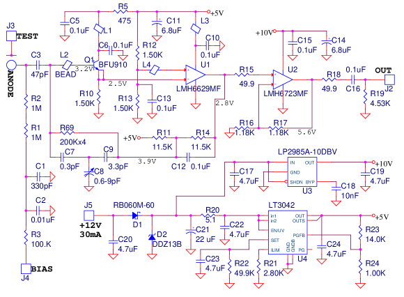
The CSA is a new design that is intended to enable high count rates for low capacitance detectors. The schematic of the CSA is shown in Fig.2. The first opamp (U1) provides most of the gain with only a small contribution to the overall noise. However, its bias current, input current noise, and input capacitance are too high for direct connection to the anode, so a SiGe microwave transistor (Q1) is added to serve as an input buffer. This particular transistor offers very high current gain (about 2000) and extremely low input capacitance, and is also very quiet. The signal response of this composite amplifier is defined by the feedback network of R69 and C7, 8, and 9. R69 is actually 4 chip resistors totaling 800 kohms, which were stacked end to end to minimize stray capacitance. The capacitors form a network with an equivalent capacitance adjustable from 0.1 to 0.3 pF. The anode board also comprises an output buffer with a gain of 2, two voltage regulators (U4 is remarkably low noise), level shift, and anode bias circuits. This circuit was realized on the annular FR4 printed circuit board on which the RIPD anode was mounted.
4 Experimental setup
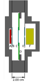
To characterize the performance of RIPD, the energy resolution for particles from an 241Am source was measured. To test RIPD with particles, which have a low ionization density, it is necessary to operate RIPD at gas pressures that exceed the maximum pressure sustainable with the thin windows. For these tests, the entrance and exit window plates were replaced with flanges, as shown in Fig 3. The entrance flange allowed an 241Am source to be situated prior to the entrance cathode foil but within the gas volume. Correspondingly, the exit flange allowed a silicon surface barrier detector (SBD) to be placed after the exit cathode foil within the gas volume. Both the 241Am source and SBD had a collimation of 3 mm. Triggering on the SBD signal associated with arrival of particles selected particles that had traversed the entire thickness of RIPD. Using this configuration, signals in RIPD could be examined for pressures between 100 and 400 torr. At a pressure of 100 torr the 5.48 MeV particles deposit just 680 keV in the gas. This energy deposit increases to 3.5 MeV at 400 torr.
5 Signals
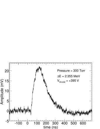
A typical signal from the CSA at a pressure of 300 torr is shown in Fig. 4. The anode was biased to a potential of +395 V to produce a reduced field of 1 kV cm-1 atm-1. The signal time from baseline to peak is approximately 100 ns with a rise time of 60 ns. Although the observed signal rise time corresponds to the convolution of the electron collection time and the CSA response, as the CSA response is fast (10 ns), the observed signal principally reflects the electron collection time, consistent with the reported literature value for the electron drift velocity at the reduced field utilized. The CSA signal returns to baseline after 300 ns. Thus the whole signal duration is under 500 ns, which corresponds to a maximum calculated rate of 2106 ions/second without pileup. The gain of the CSA is approximately 9.5 mV/MeV. The noise of this signal is approximately 4 mV peak-to-peak, corresponding to a signal-to-noise ratio of 5.7.
To handle these fast signals, the development of a fast shaping amplifier was required. This requirement was realized by modifying an in-house octal shaper module which handles input signals of both polarities. With the fast shaper module shaping times between 100 ns and 800 ns in increments of 100 ns can be selected. The coarse gain is controlled by two 4-bit stages, while a fine gain adjustment is provided using a 12-bit multiplying ADC. Another 12-bit multiplying ADC allows adjustment of the pole-zero. All of these parameters can be adjusted under computer control through a USB 2.0 interface. With a shaping time of 200 ns the fast shaping amplifier transforms the typical input CSA signal depicted in Fig.4 into a Gaussian-like pulse shown with an amplitude of 950 mV and a peak-to-peak high frequency noise of 30 mV. Thus the shaping amplifier improves the signal-to-noise ratio to a value of approximately 31.
6 Energy Resolution
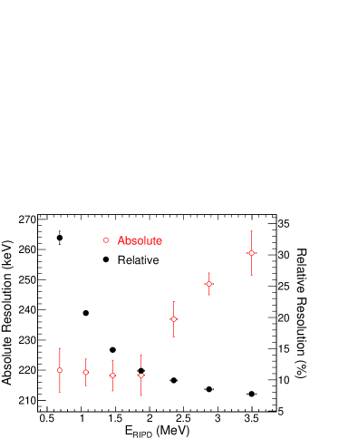
To determine the energy resolution of RIPD, the signal from the shaping amplifier was digitized by a CAEN V785 peak-sensing ADC. The energies of particles measured in RIPD was first calibrated using the measured energies in the SBD detector after accounting for the energy lost in the mylar foils [19]. The calibrated RIPD energy spectrum was used to determine the energy resolution by comparing the FWHM of the energy distribution to its centroid. The dependence of the energy resolution on the energy deposited in the gas volume is shown in Fig. 5. For energies up to 2 MeV, the absolute resolution is constant at a value of approximately 220 keV, suggesting that for these energy deposits the electronic noise dominates the total noise. Above 2 MeV the absolute resolution deteriorates reaching a value of 260 keV at 3.5 MeV of energy deposit. In the energy deposit interval measured the relative resolution decreases smoothly from 32% to 7.5%. This 7.5% resolution can be understood as a combination of the signal-to-noise after the fast shaper as well as the variations in the path length of the measured particles through the gas volume.
7 Performance with Beam
In order to characterize the performance of RIPD with beams of different intensity a test was conducted at the ReA3 facility at Michigan State University’s National Superconducting Cyclotron Laboratory (NSCL). The ReA3 80 MHz linac, which can be used to accelerate either stable beams or radioactive ions produced by the NSCL’s coupled cyclotron facility, was used to accelerate 39K to energies of 2.5 MeV/A and 4 MeV/A. The beam was extracted from the charge breeding ion trap EBIT within 100 milliseconds at a repetition rate of 2 Hz. This time structure results in the instantaneous rate experienced by any detector in the beam path being effectively a factor of five higher than the average rate. The experimental setup used is depicted in Fig. 6. The first element of the setup was a microchannel plate detector [20]. In this detector, passage of a beam particle through a 100 g/cm2 carbon foil ejects electrons that are transported by crossed electric and magnetic fields to the surface of a chevron microchannel plate (MCP). The fast response of the MCP results in each beam ion incident on the carbon foil being individually recorded. The rate at which the MCP triggers was recorded by a 250 MHz VME scaler providing a measure of the beam rate. Approximately 44 cm downstream of the MCP, RIPD was mounted on a retractable arm. For low intensity beams a SBD situated immediately after RIPD was used to measure the residual energy of ions traversing RIPD. The SBD was retracted from the beam path when a high intensity beam was used.
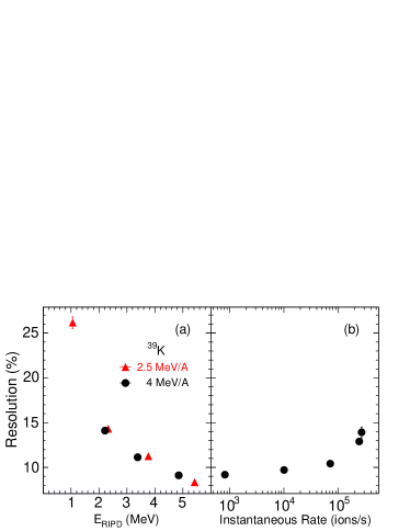
Shown in Fig. 7a as the closed triangles is the energy resolution of the energy deposited in RIPD by 2.5 MeV/A 39K ions traversing RIPD at nominal gas pressures of 5, 10, 15, and 20 torr. The gas pressure and flow through the detector were maintained by a high quality gas handling system with a stability of 0.2 torr. With increasing gas pressure the energy deposit in the gas increases from approximately 1 MeV to approximately 5 MeV. As the energy deposit in the gas increases the relative resolution of RIPD improves from 25 at the lowest energy deposit to approximately 9 at the highest energy deposit in reasonable agreement with the source testing results presented in Fig. 5. The electronic noise as well as the stability of the electronics were monitored during the measurement by injecting a calibration pulse into the charge sensitive amplifier at a low rate. The electronic noise was measured to be approximately 1 , significantly less than the measured energy resolution of the detector. To determine the response of the energy resolution of RIPD to a change in the beam intensity, the beam intensity of a 4 MeV/A 39K beam was increased from 800 ions/s to 3 x 10⁵ ions/s. The impact of the beam intensity on the energy resolution of RIPD is shown in Fig. 7b. With increasing beam intensity the measured energy resolution degrades from approximately 9 to 14 at the highest intensity measured.
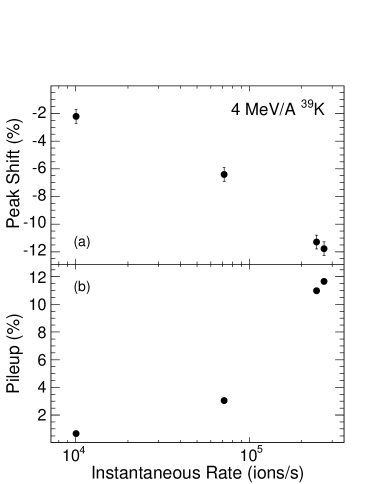
Aside from the degradation in the energy resolution the increased beam intensity can also impact the total charge collection due to increased recombination in the detector at high beam intensities. This effect is manifested in the upper panel of Fig. 8. A decrease in the centroid of the energy deposited in RIPD by 4 MeV/A 39K ions is evident. With increasing beam intensity the location of the energy centroid shifts to lower values consistent with recombination of electrons and cations in the detector gas. At an instantaneous rate of 3 x 10⁵ ions/s a peak shift of 12% is observed as compared to a low intensity beam of 800 ions/s. As recombination impacts both the ions of interest as well as any contaminants, identifying the nuclide of primary interest from other contaminants is still achieveable. However, correcting for any significant changes in the beam intensity becomes important.
The impact of beam intensity on the pileup observed is indicated in the lower panel of Fig. 8. Pileup is clearly distinguished as observation of pulses with energies exceeding that of the full beam energy. As expected the pileup increases with increasing instantaneous rate from 1% at 1 x 10⁴ ions/s to just under 12% at 3 x 10⁵ ions/s. As anticipated the fast response of RIPD enables the use of the detector at high rates without significant pileup.
8 Conclusion
To address the challenge of identifying contaminant species in radioactive isotope beams, we have developed a high-rate axial-field ionization chamber which introduces minimal material into the beam path. The high-rate capability of this detector was optimized by implementing a low profile central anode design and developing a fast charge-sensitive amplifier which is situated within the gas volume in close proximity to the anode. A typical signal from this amplifier spans less than 500 ns, with a rise time of approximately 60-70 ns. A fast shaping amplifier was also developed to handle these fast signals. With these pulse shaping electronics the energy resolution of RIPD is approximately 8% for an energy deposit of 3.5 MeV in the detector for particles from an 241Am source. Using beam, a comparable resolution was obtained. Below an instantaneous rate of 1 x 10⁵ 39K ions/s the energy resolution was 8-10%. At an instantaneous rate of 3 x 10⁵ the resolution degraded to 14%. The impact of recombination and pileup in the detector as a function of the instantaneous rate was characterized. Correcting for these effects is an important part of exploiting the full capability of this detector to resolve contaminants in a radioactive beam.
Acknowledgments
We gratefully acknowledge the technical support provided by the personnel in the Mechanical Instrument Services and Electronic Instrument Services at the Department of Chemistry, Indiana University. We thank the technical staff at MSU-NSCL for providing the high quality beam necessary to fully characterize the detector. This research is based upon work supported by the U.S. Department of Energy under Award Number DE-FG02-88ER-40404 and the National Science Foundation under Grant Number 1342962.
References
- [1] J. F. Liang, et al., Phys. Rev. Lett. 91 (2003) 152701.
- [2] A. Lemasson, et al., Phys. Rev. Lett. 103 (2009) 232701.
- [3] Y. E. Penionzhkevich, Phys. At. Nucl. 73 (2010) 1460.
- [4] T. Glasmacher, Annu. Rev. Nucl. Part. Sci. 48 (1998) 1.
- [5] T. J. L. Symons, et al., Phys. Rev. Lett. 42 (1979) 40.
- [6] H. L. Ravn, Physics Reports 54 (1979) 201.
- [7] Y. T. Oganessian, et al., Nucl. Phys. A 701 (2002) 87.
- [8] B. M. Sherrill, et al., Nucl. Instr. Meth. B 56/57 (1991) 1106.
- [9] N. Fukuda, et al., Nucl. Instr. Meth. B 317 (2013) 323.
- [10] H. W. Fulbright, Nucl. Instr. Meth. 162 (1979) 21.
- [11] M. M. Fowler, R. C. Jared, Nucl. Instr. Meth. 124 (1975) 341.
- [12] R. W. Zurmuhle, L. Csihas, Nucl. Instr. Meth. 203 (1982) 261.
- [13] S. K. Bandyopadhyaya, et al., Nucl. Instr. Meth. A 278 (1989) 467.
- [14] K. Kimura, et al., Nucl. Instr. Meth. A 538 (2005) 608.
- [15] K. Y. Chae, et al., Nucl. Instr. Meth. A 751 (2014) 6.
- [16] T. K. Steinbach, et al., Phys. Rev. C 90 (2014) 041603(R).
- [17] V. Singh, et al. (2016). arXiv:1603.09314v1[nucl-ex].
- [18] J. Va’vra, et al., Nucl. Instr. Meth. A 324 (1993) 113.
- [19] J. F. Ziegler, M. D. Ziegler, J. P. Biersack, Nucl. Instr. Meth. B 268 (2010) 1818.
- [20] T. K. Steinbach, et al., Nucl. Instr. Meth. A 743 (2014) 5.