Phase-field modeling of isothermal quasi-incompressible multicomponent liquids
Abstract
In this paper general dynamic equations describing the time evolution of isothermal quasi-incompressible multicomponent liquids are derived in the framework of the classical Ginzburg-Landau theory of first order phase transformations. Based on the fundamental equations of continuum mechanics, a general convection-diffusion dynamics is set up first for compressible liquids. The constitutive relations for the diffusion fluxes and the capillary stress are determined in the framework of gradient theories. Next the general definition of incompressibility is given, which is taken into account in the derivation by using the Lagrange multiplier method. To validate the theory, the dynamic equations are solved numerically for the quaternary quasi-incompressible Cahn-Hilliard system. It is demonstrated that variable density (i) has no effect on equilibrium (in case of a suitably constructed free energy functional), and (ii) can influence non-equilibrium pattern formation significantly.
I Introduction
Although the theory of multicomponent liquid diffusion is well developed and in use in chemical engineering and materials science Cussler (2009); Taylor and Krishna (1993); Wesselingh and Krishna (2006); Datta and Vilekar (2010), the generalization of theory describing the time evolution of liquid systems being out of mechanical equilibrium is still lacking. Nevertheless, even results of simple continuum theories indicate that the hydrodynamic mode might influence pattern formation significantly even on small length scales Tegze et al. (2005); Tegze and Tóth (2012); Toth and Kvamme (2015); Tóth et al. (2016), which indeed comes into play in microfluidics Shukutani et al. (2014); Haase and Brujic (2014); De Villiers and Lvov (2007); Stoffel et al. (2012), or even in oil industry related research: CO2/water/hydrocarbon emulsions may offer a novel and ultimate solution for the global CO2 storage problem with combined Enhanced Oil Recovery, however, the continuum description of kinetic processes in these molecularly complex liquids is nontrivial Toth and Kvamme (2015). Besides, significant volume changes occur in case of formation/dissociation of CO2/CH4 hydrates (clathrates), also necessitating thus a hydrodynamic description. Efforts regarding the effect of fluid flow on microscopic pattern formation phenomena were made in the framework of diffuse interface models addressing various pattern formation problems including fluid flow-assisted solidification, as well as binary and ternary liquid phase separation Wheeler and McFadden (1997); Anderson et al. (1998); Lowengrub and Truskinovsky (1998); Anderson et al. (2000); Conti (2001); Conti and Fermani (2003); Conti (2004); Kim and Lowengrub (2005). . During pattern formation in systems of practical importance interfaces move typically much slower than the speed of sound, therefore, the simplest (and most efficient) approaches include incompressible flow Kim (2012); Tóth et al. (2016), assuming thus constant density. In contrast, other theories operate with artificial compressibilities (resulting thus in a significant reduction in the speed of sound) Conti (2001); Conti and Fermani (2003); Conti (2004) in order to access the time scale of solidification. The ”golden mean” between the two methods can be the quasi-incompressible approach Anderson et al. (2000); Lowengrub and Truskinovsky (1998); Kim and Lowengrub (2005), in which sound waves are eliminated, but density gap may exist between the bulk components. The problem of this approach, however, is the mathematical complexity of the related numerical methods, making thus the theory unpractical Guo et al. (2014). For these reasons, it is desirable to develop a physically consistent and numerically efficient, general dynamic framework describing the time evolution of multicomponent liquids. The essence of a general framework is keeping the coherency between the fundamental equations of continuum mechanics (the conservation of momentum and mass) and the principles of irreversible thermodynamics (the first and second law of thermodynamics, the Curie postulate, and the Onsager-Casimir theory). Besides the theoretical aspects, the model have practical importance only if it can handle variable density on pattern formation time scales, and can be solved numerically efficiently.
The structure of the paper is as follows. In Section II, general dynamic equations will be derived on the basis of simple physical principles for compressible liquids of arbitrary number of components. In Section III, a mathematically exact definition of general incompressibility is given. All derivations are done in the framework of the classical Ginzburg-Landau theory of first order phase transformations. In Section IV, we apply the model for quasi-incompressible liquids, and derive an operator-splitting based, pseudo-spectral semi-implicit numerical scheme to solve the dynamic equations. The incompressibility condition is handled by a generalization of Chorin’s projection method. We show that a suitable discretization of the Navier-Stokes equation results in a generalized Poisson equation, which can be solved directly by using a two-step pseudo-spectral method. In Section V, a recently published multiphase-field model is used to address liquid-liquid phase separation in a quasi-incompressible multicomponent Cahn-Hilliard liquid, where the densities of the components, as well as the pairwise equilibrium interfacial properties can be calibrated independently from each other. To demonstrate the physical consistency of the dynamic framework, we address equilibrium trijunctions and pattern formation in an asymmetric 4-component liquid in case of both constant and variable density, which is followed by the concluding remarks in Section VI.
II Compressible systems
II.1 Fundamental equations
In continuum mechanics a mixture of liquids is characterized by the local and temporal mass density [] and velocity [] fields of the components (). The conservation of mass and momentum read Furry (1948); Williams (1958); Lam (2006):
| (1) | |||
| (2) |
where stands for the tensor product. In Eq. (2), the stress tensor accounts for self-specie interactions, while is the net ”external” force density on component emerging solely from interspecie momentum exchanges (denoted by ). The time evolution of the system is driven by the stresses and the force densities . Since these are abstract quantities that cannot be observed directly in experiments, a more convenient form of the dynamic equations is chosen. Since Newton’s third law prescribes , cancels in the sum of the momentum equations (i.e. the Navier-Stokes equation):
| (3) |
where is the mixture density, and is the velocity of the local center of mass. Furthermore, the capillary stress reads . Analogously to Eq. (3), summing up Eq. (1) for all components results in the continuity equation:
| (4) |
Introducing now the mass fractions (or phase-fields) , and using Eq. (4) in Equations (1) and (3) yields general dynamic equations of convection-diffusion type:
| (5) |
where stands for the material derivative, and is the negative mass flux of component in the barycentric coordinate system, trivially resulting in the condition
| (6) |
The phenomena ”convection” and ”diffusion” are postulated here in a complementary sense: While convection is attributed to the motion of the local center of mass, diffusion is interpreted as a motion relative to it.
II.2 Constitutive relations
II.2.1 Diffusion fluxes
Equations (4) and (5) govern the system via and , for which constitutive equations have to be set up. Due to the Curie postulate, the diffusion process should be decoupled from the momentum transport in the framework of linear transport. Accordingly, the isotherm entropy production rate (time derivative of the entropy density) attributed to diffusion reads Onsager (1945); Sekerka and Mullins (1980); Nyiri (1986):
| (7) |
where is the specific chemical potential (chemical potential per unit mass), the conjugate variable to the mass flux , whereas and are the chemical potential and the molar flux, respectively ( is the molar mass). According to the linearity postulate, the molar fluxes are the linear combination of the chemical potential gradients:
| (8) |
where is a symmetric matrix Onsager (1945). Furthermore, the second law of thermodynamics prescribes , which, together with Equations (7) and (8) indicate a positive semi-definite transport matrix. Using Eq. (8), together with the variable transformation yield
| (9) |
where is also symmetric (and positive semi-definite). Furthermore, using Eq. (6) results in
| (10) |
II.2.2 Stress tensor
The stress tensor in Eq. (5) is usually divided into two contributions:
| (11) |
where is the non-classical reversible stress Korteweg (1901):
| (12) |
where is the (scalar) thermodynamic pressure, the identity matrix, while the Korteweg stress can be determined by using the condition of mechanical equilibrium (also cited as generalized Gibbs-Duhem relation / least action principle in statistical physics) Salmon (1988):
| (13) |
where is the molar density. Besides the reversible stress, the other contribution to is the viscous stress . Assuming a Newtonian fluid it can be approximated as:
| (14) |
where
| (15) |
is the local (composition dependent) dynamic viscosity of the material. The dissipative stress defined by Eq. (14) naturally satisfies (the condition of non-negative entropy production) for Kim and Lowengrub (2005).
II.3 Ginzburg-Landau Theory
The Helmholtz free energy of the system () is often given as a functional of the local densities of the components. Since the density is conserved, the relevant thermodynamic potential of the system is the grand potential, which reads:
| (16) |
where is the equilibrium chemical potential of component (analogously, is the corresponding specific chemical potential). The equilibrium configurations of the system can be found by solving the Euler-Lagrange equations prescribing constant chemical potentials:
| (17) |
where denotes the functional derivative with respect to . A suitable non-equilibrium generalization of the specific chemical potential then reads Carter et al. (1997):
| (18) |
Furthermore, since in equilibrium, the equilibrium scalar pressure can be expressed from Eq. (16), yielding , where , and is evaluated here for an equilibrium solution. This immediately indicates the non-equilibrium generalization of the pressure Wheeler and McFadden (1997):
| (19) |
where is defined by Eq. (18). Assuming that the free energy is of the Ginzburg-Landau type Binder (1973) (i.e. is given in terms of the densities and their gradients), and using Eq. (19) in Eq. (13) result in the Korteweg stress Wheeler and McFadden (1997):
| (20) |
II.4 Mass fraction formalism
Since the dynamic equations defined by Equations (4) and (5) are written up for the total mass density and the mass fractions, it would be practical to express the diffusion fluxes and the stress tensor in terms of these variables. Since the chain rule of derivation applies also for the functional derivative (see Appendix B in Ref. Tóth et al. (2015), for example), one can write:
| (21) |
Using that and (where is the Kronecker-delta function giving for and otherwise), the specific chemical potential reads:
| (22) |
where . Note, that the term in the second bracket on the righ hand side is independent from . Using Eq. (22) in Eq. (9), and taking Eq. (10) also into account results in
| (23) |
Furthermore, using Eq. (22) in Eq. (19) yields the scalar pressure:
| (24) |
The last step of the derivation is to express the Korteweg stress defined by Eq. (11) as a function of and the mass fractions, which can be done analogously to Eq. (21), yielding:
| (25) |
Summarizing, the dynamic equations [see Eq. (5)] together with the constitutive relations described by Equations (11), (12), (14), (15), (23), (24) and (25) define a complete convection-diffusion type dynamic framework for a given free energy functional .
III Incompressible systems
The constitutive equations derived in the previous section describe compressible systems, however, incompressible systems have much higher practical importance in applications, where time scales much larger than the time scale of sound waves are addressed. The exact mathematical definition of incompressibility is that the local density is an explicit function of the local composition:
| (26) |
where is a known function. Since is not a free variable, is a functional only of the mass fractions (and their gradients). Note that Eq. (26) together with Eq. (4) over-determine the dynamic equations. The degeneration of the solution can be eliminated by applying the Lagrange multiplier method as follows. The continuity equation can be trivially re-written in the form: , where the material derivative of the density can be expressed now as . Furthermore, the diffusion equations indicate , resulting in:
| (27) |
where , while the diffusion fluxes () are to be defined later. Note that Eq. (27) is an alternative form of the continuity equation for general incompressible systems. It prescribes a condition between the compositions and the velocity field, which can be taken into account by including the local condition in the derivation of the non-equilbirium specific chemical potential. Accordingly, equilibrium represents a conditional extremum of , yielding:
| (28) |
where is the Langrange multiplier attributed to the local condition, whereas
| (29) |
is non-trivial, and must be calculated from the known relationship. Accordingly, the (conditional) specific chemical potential reads
| (30) |
Note, that the relevant thermodynamic force is now , since it becomes constant in equilibrium (according to Eq. (28). The diffusion fluxes are then postulated as:
| (31) |
Analogously to the chemical potential, the conditional pressure reads . Expanding the expression yields:
| (32) |
where is defined by Eq. (19). The conditional reversible stress then reads
| (33) |
where is defined by Eq. (20). Comparing Equations (32) and (33) results in (a conditional Gibbs-Duhem relationship), correctly accounting for mechanical equilibrium. Furthermore, using Equations (22), (24) and (29) in Equations (30) and (32) results in the conditional specific chemical potential expressed in terms of the mass fractions:
| (34) |
where all terms canceling in Eq. (31) due to Eq. (10) are neglected. Note that the appearance of the pressure in Eq. (34) expresses the fact that inertia must be taken into account in case of varying density Plapp (2016). Finally, the Korteweg stress simply reads:
| (35) |
which follows from the fact that is not a function of .
IV Chorin’s projection method for quasi-incompressible liquids
It is very practical to test the theory for quasi-incompressible liquids. In these systems, the bulk components are incompressible, while they can have different densities. In addition, Amagat’s law of additive volumes also applies for these systems, i.e. the partial volumes of the components do not change upon mixing. These conditions can be expressed in terms of the mass fractions as Kim and Lowengrub (2005):
| (36) |
where is the bulk density of component . From Eq. (36) it follows that
| (37) |
is constant in Equations (27) and (34). In solving the dynamic equations numerically, we face two major problems: (i) The mass fractions and the velocity are non-conserved and (ii) the pressure appears in both the conditional specific chemical potentials and the reversible stress tensor. (i) can be resolved by taking into account that
| (38) |
(where ), simply because of the continuity equation [see Eq. (4)]. Therefore, the dynamic equations can be re-written as:
| (39) | |||||
| (40) |
where the right hand sides are still expressed in terms of the mass fractions and the velocity field, which are explicitly related to the absolute densities and the momentum via and Eq. (36). Eq. (36) can also be expressed in terms of the absolute densities, yielding . Consequently, dividing Eq. (39) by , then summing them up trivially results in Eq. (27), an alternative form of continuity for prescribed total density. It means, that once and Eq. (27) are satisfied, Eq. (36) always applies for Eq. (39). To solve the dynamic equations we apply an operator-splitting based, pseudo-spectral semi-implicit method, yielding Tegze et al. (2009); Tóth et al. (2016):
| (41) | |||||
| (42) |
where is the wave number, the time step, and the Fourier transform of the right hand sides behind the divergence in Equations (39) and (40), respectively, while and are suitably chosen splitting operators (for details, see Reference Tóth et al. (2016)). Following Chorin’s projection method Chorin (1968), the momentum density given by Eq. (42) should be corrected as:
| (43) |
where is the new pressure. Note that Equations (41)-(43) ensure the conservation of the mass and the momentum densities numerically exactly. The pressure correction can be determined from Eq. (27) and Eq. (43) by taking into account that , yielding
| (44) |
where . Note, that contains because of Eq. (34). Introducing as evaluated for and results in
| (45) |
where a general transport matrix having composition dependent elements is assumed. Note that Eq. (26) is a type equation, which, assuming periodic boundary conditions, can also be solved by applying a two-step pseudo-spectral method as follows. First, the outer equation is solved, yielding:
| (46) |
Having , can be solved for . Introducing results in:
| (47) |
In our problem, is the left hand side of Eq. (26), is the term in the round bracket on the right hand side, and . Having , the momentum update described by Eq. (43), together with the pressure update can be directly applied. In practice, the time stepping scheme contains the following steps:
-
1.
calculating and from and [where ];
- 2.
-
3.
time stepping to generate and ;
-
4.
calculating the new variables and the intermediate velocity field ;
-
5.
solving Eq. (45) for ;
-
6.
updating the pressure and the momentum density to have and .
Finally we note, that solving Eq. (26) is ”safe”, since the term in the round bracket on the right hand side [i.e. ] is strictly positive, due to the fact that is a positive semi-definite matrix.
V Cahn-Hilliard liquids
V.1 Free energy, dynamic equations and scaling
The free energy density of a general multicomponent liquid undergoing liquid-liquid phase separation can be defined as Tóth et al. (2015, 2016):
| (48) |
where
| (49) | |||
while the transport matrix reads:
| (50) | |||||
with pairwise diffusion mobilities. The model parameters and can be related to the interfacial tension and the interface thickness of the pure binary planar interface as:
| (51) |
Furthermore, the pairwise mobilities can be related to the diffusion coefficents as follows. Having the diffusion coefficient of component in bulk component , a single mobility might be defined as:
| (52) |
where . In gradient theories the diffusion equations reduce to the Lorentzian limit close to equilibrium:
| (53) |
for , , and . Using Eq. (52) in Eq. (53), the modified diffusion coefficients read:
| (54) |
(approximates of the original ones). In a recently published work Tóth et al. (2016) it has been shown that the construction described by Equations (48)-(50) has the following advantages:
-
•
the model naturally reduces / extends on the level of both the free energy functional and the dynamics when removing / adding a phase, respectively;
-
•
the pure planar binary interfaces , and minimize the free energy functional with interfacial tension ;
-
•
the system shows the energy hierarchy, i.e. it hierarchically penalize local multicomponent states;
-
•
the appearance of spurious phases are excluded.
These features apply in case of constant density. To address variable density, the structure of equilibrium solutions is investigated first. The general Euler-Lagrange equations follow from substituting Eq. (22) into (28), and using Eq. (29), yielding:
| (55) |
for , where is the equilibrium value of . Since for all solutions of the Euler-Lagrange equations the functional derivatives vanish Tóth et al. (2016), the solutions of the original model represent solutions of Eq. (55) too for arbitrary . Therefore, the equilibrium solutions of the present model coincide for constant and variable density.
Choosing now the length scale , the time scale (where is the scale of the diffusion coefficients), the density scale , and the interfacial tension scale , and the free energy density scale result in the dimensionless diffusion equations:
| (56) |
where
| (57) | |||||
where , [see Eq. (49)], and [see Eq. (52)]. The dimensionless Navier-Stokes equation reads
| (58) |
where
| (59) |
and is the viscosity scale. The reversible and irreversible components of the dimensionless stress tensor read:
| (60) | |||||
| (61) |
Finally, the incompressibility condition simply transforms into
| (62) |
It’s straightforward to see the role of the dimensionless model parameters and : The dynamics is diffusion dominated when , since any flow generated by the capillary stress is suppressed. In contrast, for together with , the dynamics is fluid flow dominated, since convection overwhelms diffusion.
| type | [kg/m3] | [mJ/m2] | [Å] | [m2/s] | [mPas] |
|---|---|---|---|---|---|
| I | 1000 | 50 | 1 | 500 | 1 |
| II | 5000 | 200 | 10 | 1000 | 0.5 |
V.2 Results of numerical simulations
The numerical solution of the dimensionless equations have been done in 2 dimensions on and computational grids with grid spacing and time step . The physical parameters used mimic a typical water/hydrocarbon/CO2 system at room temperature and high pressure (system type I in Table I). For comparison, typical parameters for liquid metals at high temperature and atmospheric pressure were also considered (system type II in Table I). The resulting scale parameters prescribe fluid flow dominated dynamics for both types. In our numerical simulations, we chose and (system type I).
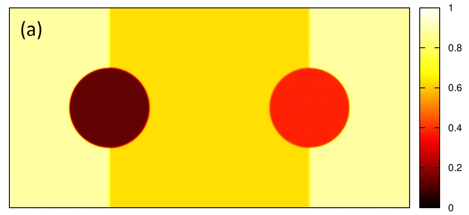
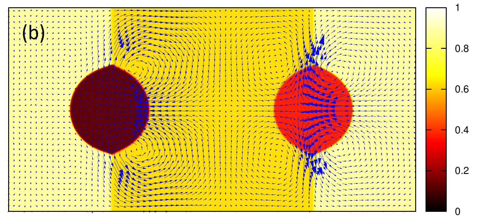
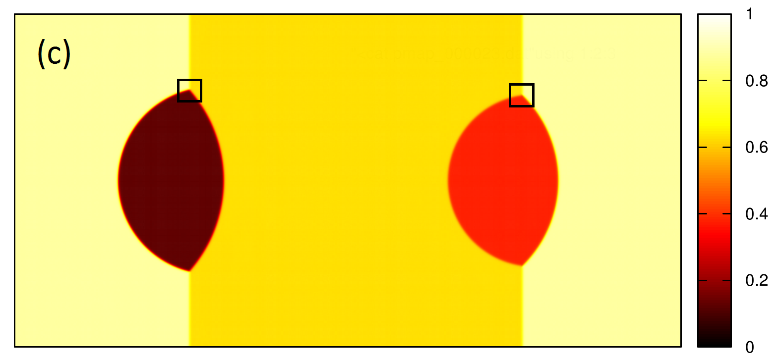
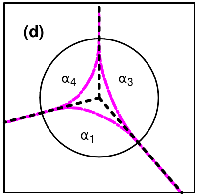
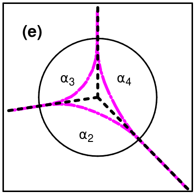
The equilibrium contact angles were investigated in a 4-component system first. The dimensionless interfacial tensions were , , , , , and , while the interface thicknesses and the diffusion coefficient were chosen to be unique, i.e. . was chosen to stabilize the equilibrium binary planar interfaces. The dimensionless viscosities and densities were , and , and , , and , respectively. The initial condition was a binary background ”sandwich” consisting of two planar interfaces, while two circular dots of liquids and were placed onto these interfaces [see Fig. 1(a)]. In the early stage of the simulation significant fluid flow [the maximal velocity magnitude was ] was generated by the non-equilibrium interfaces [see Fig. 1(b)], but after time steps the system was approaching equilibrium [the average velocity magnitude is , corresponding to 1 pixel shift in time steps]. The equilibrium configuration is shown in Fig. 1(c). The equilibrium contact angles of the trijunctions can be calculated from the condition of mechanical equilibrium by using the interfacial tensions. Accordingly, the equilibrium contact angles for the (1,3,4) trijunction read
| (63) | |||||
| (64) | |||||
| (65) |
Analogously, the contact angles for the trijunction read , , and . The contact angles can be measured directly from the simulations [see Fig. 1(d) and 1(e)], indicating less than relative error compared to the exact values.
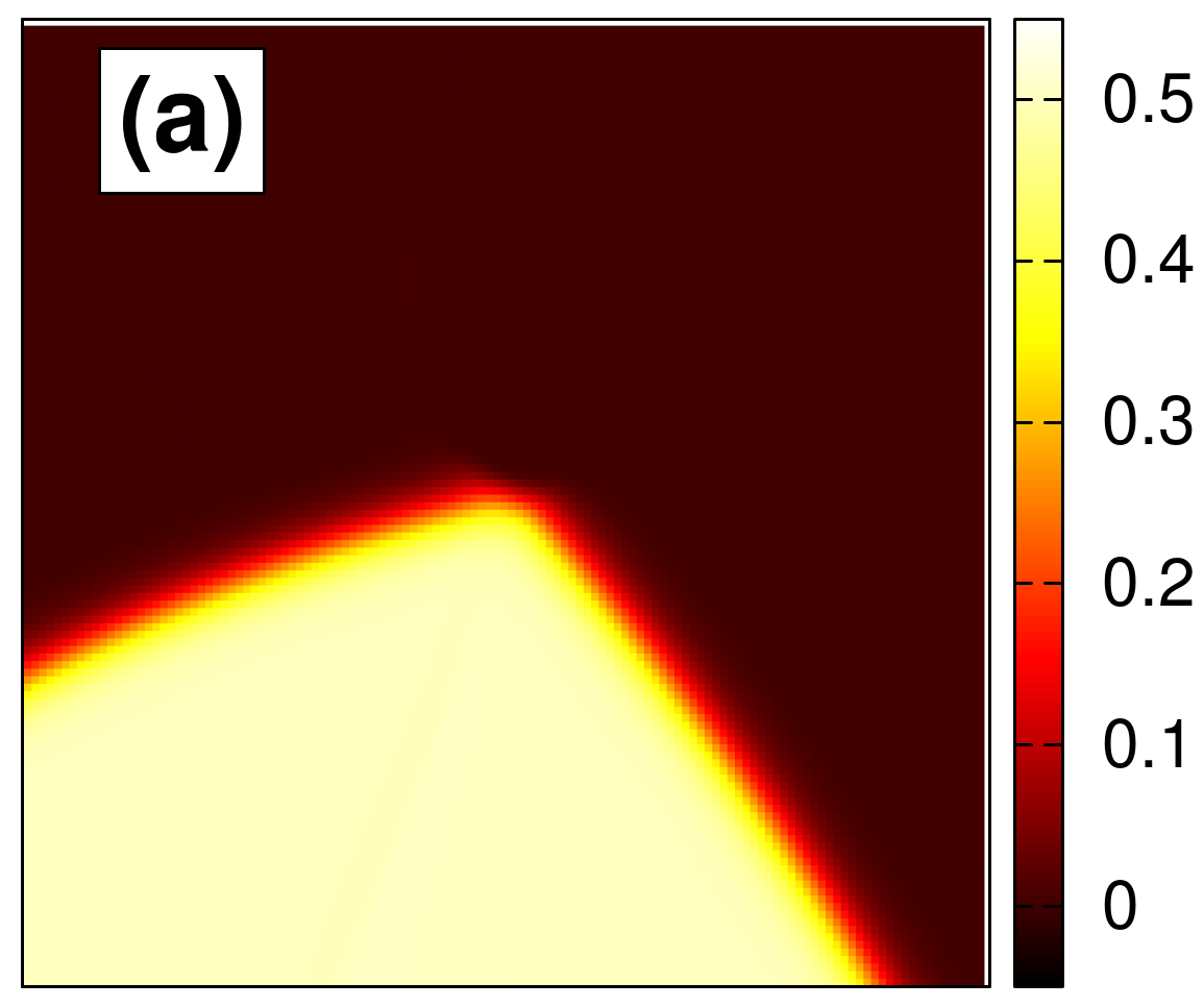
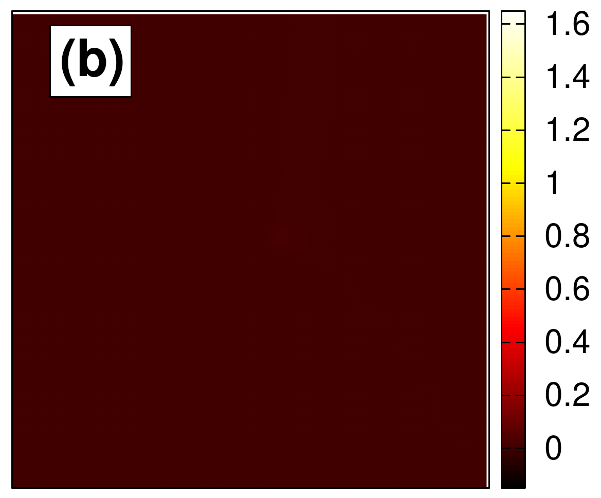
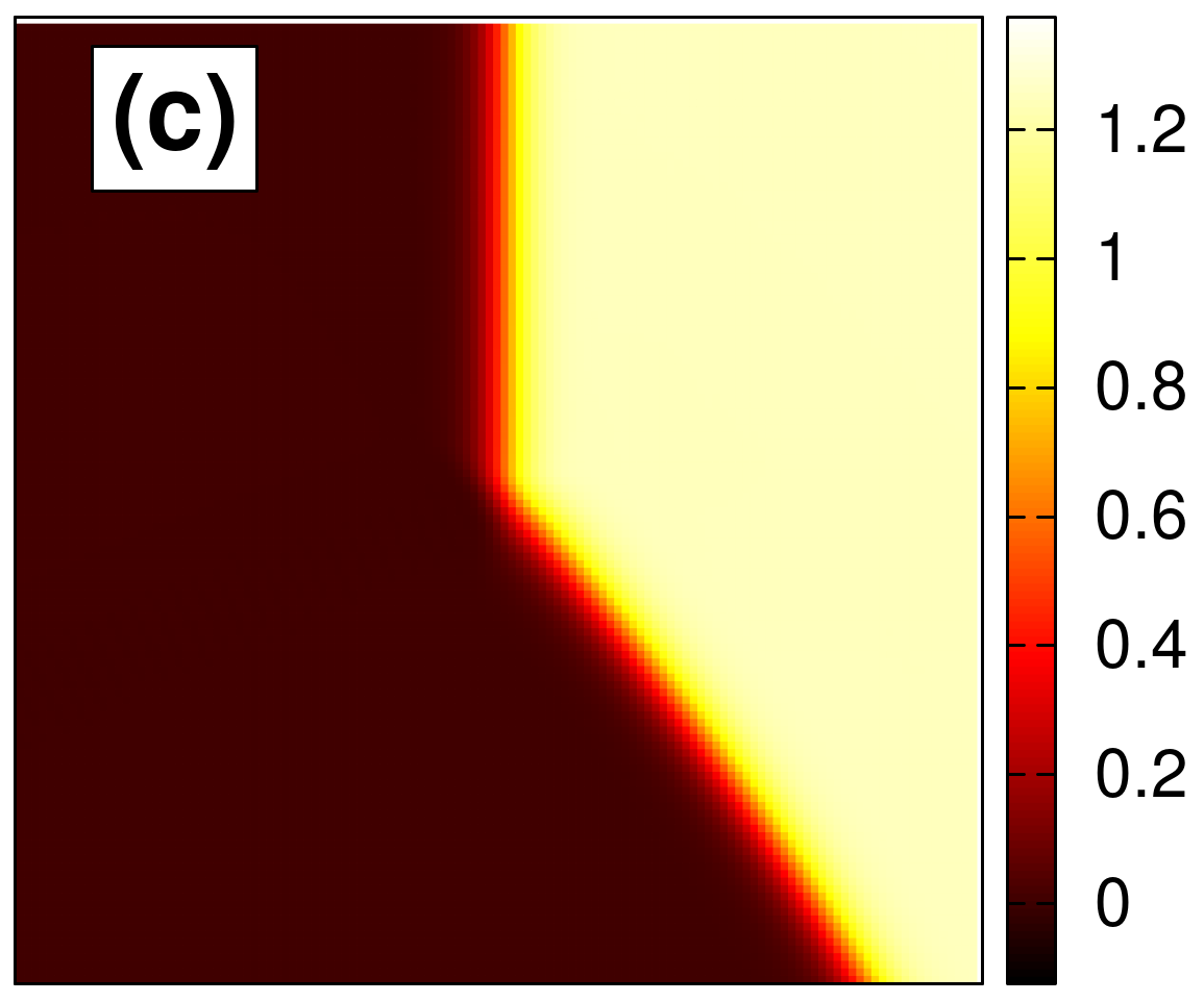
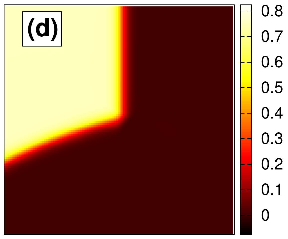
Furthermore, the individual fields (see Fig. 2) show no static spurious phases, i.e. no third component appears at the binary interfaces, even close to the trijunctions. In conclusion, equilibrium is invariant for the density contrast, as expected from Eq. (28), but we emphasize that this feature follows directly from the special choice of the free energy functional and the mobility matrix: First, any solution of the constant density Euler-Lagrange equations, at which the functional derivatives are equal, also satisfies the general Euler-Lagrange equations with an arbitrary constant Lagrange multiplier . Besides, the stationary solutions of the dynamic equations are identical to the equilibrium solutions of the free energy functional for the present choice of the mobility matrix. Consequently, the solution of the dynamic equations must converge to an equilibrium solution of the free energy functional. We also emphasize that these requirements (for the equilibrium solutions and the mobility matrix) are not fulfilled automatically, and always have to be checked, as pointed out in some recent works Tóth et al. (2015, 2016).
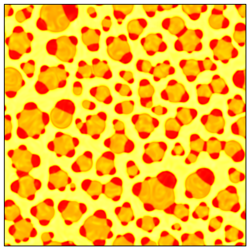
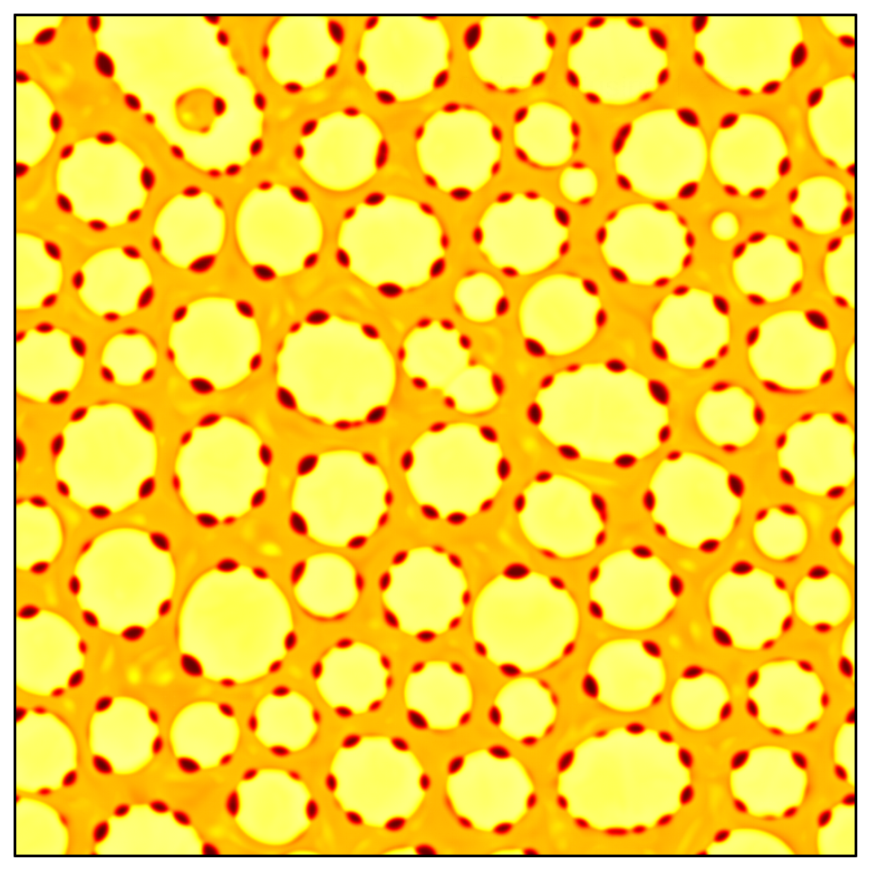
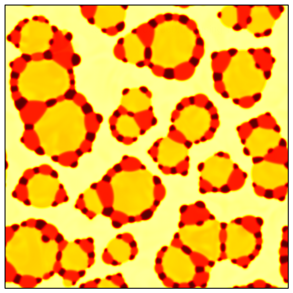
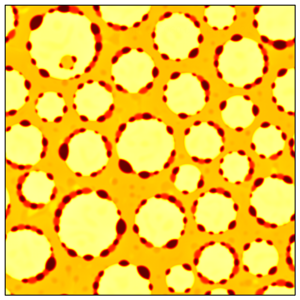
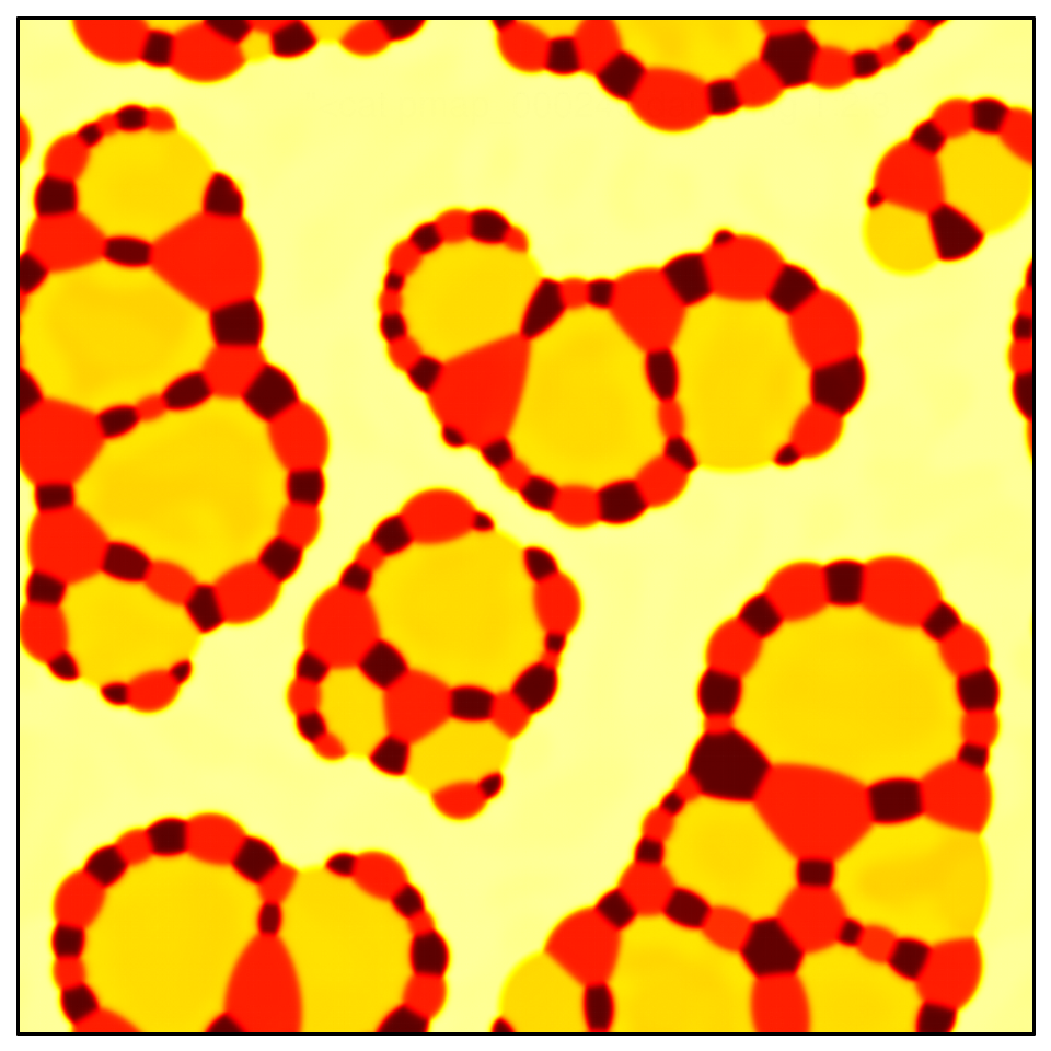
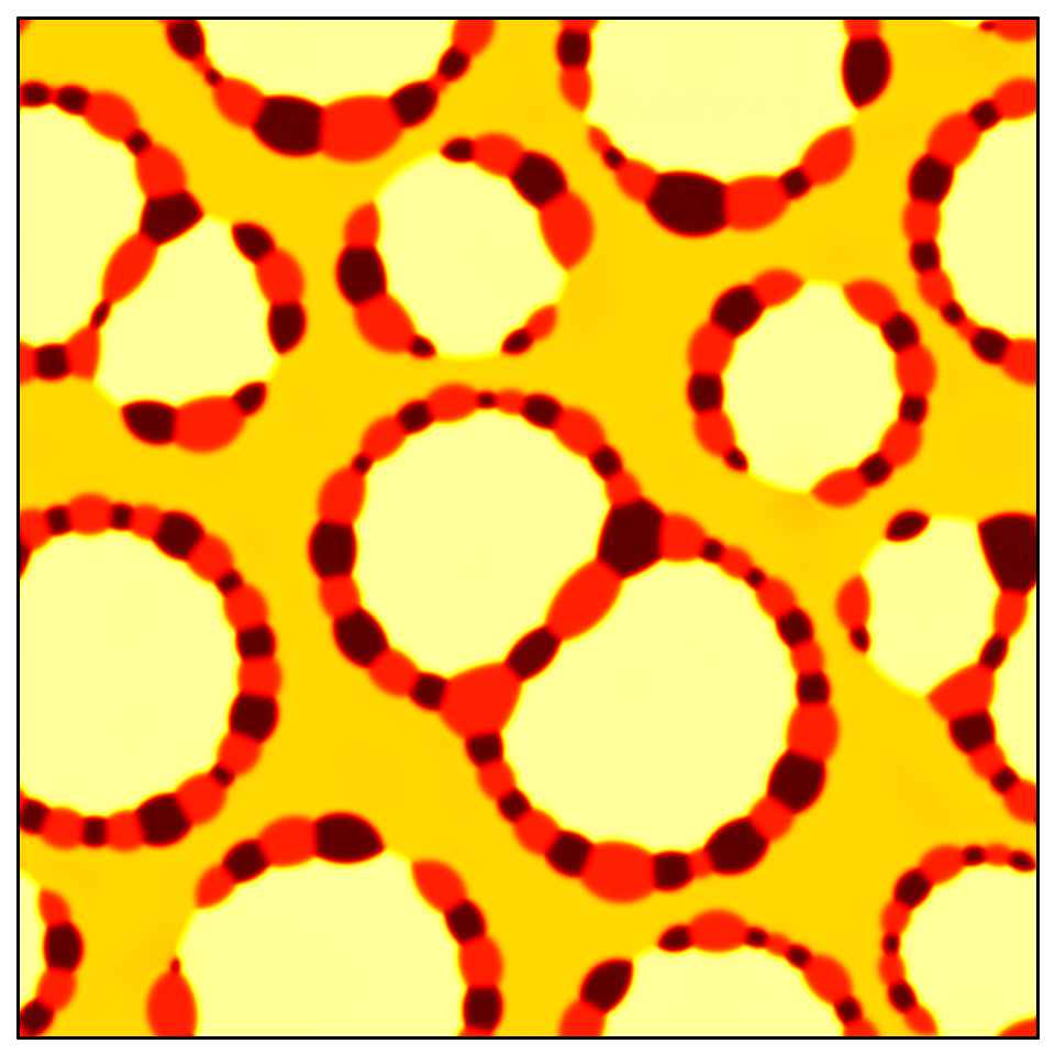
After validating the theory for equilibrium, the effect of density contrast on phase separation is investigated. Since pattern formation is a volumetric phenomenon, the volume fractions are used to set up the initial condition. Note that is also conserved for quasi-incompressible liquids, making thus the constant and variable density simulations comparable. The initial condition reads , , , and , where and is a uniformly distributed random number on . Two scenarios were considered, one for constant (), and another for varying (, , and ) density. All other dimensionless model parameters were chosen to be . Snapshots of the simulations are shown in Fig 3. The difference between the constant and variable density case is remarkable: In case of constant density, the 3 minority components aggregate in the majority component. The aggregates consist of bubbles of various sizes of the dominant minority component connected by bubble ”chains” of the other two minority components. In case of variable density, however, the majority component forms individual bubbles surrounded by chains made of the two minority components. The explanation of the difference relies on the density difference: In case of constant density, the effective mobility of the components are equal, i.e. the magnitude of the velocity ”reply” to the force density generated by the interfaces is the same in all component. Indeed, comparing the pattern to Fig. 9 of Reference [8] shows qualitative agreement. In contrast, a significant density difference between the components has major influence on pattern formation. In the present case, the third component is the least mobile, since it has the highest density. The formation of the individual islands can be explained by the drop coalescence process. When two bubbles of component 3 meet, small bubbles (consisting of the other 3 components) stuck in between receive high velocity and move fast towards the perimeter of the type 3 bubbles. After the coalescence, the bubbles made of the two minority components have a relatively small chance to meet with each other, therefore, they simply form a chain around the big type-3 bubble, and, consequently, the original majority component forms a background.

Finally the time dependence of the total free energy of the system is addressed. According to the second law of thermodynamics, the entropy production rate must be non-negative. This condition is fulfilled for a non-negative viscosity and a positive semi-definite transport matrix appearing in the condition
| (66) |
Note that Eq. (66) prescribes the positive semi-definiteness of , independently from the form of the forces, which is just a consequence of the linearity postulate. In addition, the contribution emerging from the Navier-Stokes equation is solely attributed to the viscosity. Following these arguments, a pressure stable numerical scheme is necessarily energy minimizing even in the general incompressible case. It is demonstrated in Fig. 4, showing monotonously decreasing total free energy during the phase separation process shown in Fig. 3. Summarizing, we have a numerical evidence that both constant density and quasi-incompressible systems described by the dynamic equations and the free energy construction presented in this work obey the second law of thermodynamics.
VI Summary
Herein we derived dynamic equations describing the time evolution of an isothermal multicomponent liquid mixture, where the free energy is given in the framework of gradient theories. The model integrates the fundamental equations of fluid mechanics and the principles of irreversible thermodynamics, and can be straightforwardly applied for both compressible and general incompressible systems. Since the mathematical formulation is compact, the model can be applied for many liquid systems of practical importance featuring variable density. It is important to mention, that the extension of the model with phase transformation and variable temperature is also possible Conti (2001); Conti and Fermani (2003). The only difficulty in utilizing the model for non-trivial incompressible systems [i.e. when ] is the implementation of the pressure solver, which, however, has been solved at least for quasi-incompressible systems. As it has been demonstrated, the solver is pressure stable / energy minimizing, without using complex discretization schemes. It has also been demonstrated, that the choice of the free energy functional and the mobility matrix must be compatible with the dynamic equations, in order to preserve the structure of constant density equilibrium solutions in case of variable density, allowing thus the analytic calibration of the model. In addition, we observed that the effect of density contrast on pattern formation could be crucial even in case of a density contrast of 2.
Acknowledgments
The author wish to thank Bjørn Kvamme and Juri Selvåg, Department of Physics and Technology, Universiy of Bergen for the valuable discussions. The work has been supported by the VISTA basic research programme Project No. 6359 “Surfactants for water-CO2-hydrocarbon emulsions for combined CO2 storage and utilization” of the Norwegian Academy of Science and Letters and the Statoil.
References
- Cussler (2009) E. L. Cussler, “Diffusion: Mass transfer in fluid systems,” (Cambridge University Press, 2009) pp. 1–2, 3rd ed.
- Taylor and Krishna (1993) R. Taylor and R. Krishna, Multicomponent Mass Transfer (Wiley-Interscience, 1993).
- Wesselingh and Krishna (2006) J. A. Wesselingh and R. Krishna, Mass Transfer in Multicomponent Mixtures (VSSD, 2006).
- Datta and Vilekar (2010) R. Datta and S. A. Vilekar, Chemical Engineering Science 65, 5976 (2010).
- Tegze et al. (2005) G. Tegze, T. Pusztai, and L. Gránásy, Materials Science and Engineering: A 413–414, 418 (2005), international Conference on Advances in Solidification Processes.
- Tegze and Tóth (2012) G. Tegze and G. I. Tóth, Acta Materialia 60, 1689 (2012).
- Toth and Kvamme (2015) G. I. Toth and B. Kvamme, Phys. Chem. Chem. Phys. 17, 20259 (2015).
- Tóth et al. (2016) G. I. Tóth, M. Zarifi, and B. Kvamme, Phys. Rev. E 93, 013126 (2016).
- Shukutani et al. (2014) T. Shukutani, T. Myojo, H. Nakanishi, T. Norisuye, and Q. Tran-Cong-Miyata, Macromolecules 47, 4380 (2014), http://dx.doi.org/10.1021/ma500302k .
- Haase and Brujic (2014) M. F. Haase and J. Brujic, Angewandte Chemie 126, 11987 (2014).
- De Villiers and Lvov (2007) M. M. De Villiers and Y. M. Lvov, “Nanoshells for drug delivery,” in Nanotechnologies for the Life Sciences (Wiley-VCH Verlag GmbH & Co. KGaA, 2007).
- Stoffel et al. (2012) M. Stoffel, S. Wahl, E. Lorenceau, R. Höhler, B. Mercier, and D. E. Angelescu, Phys. Rev. Lett. 108, 198302 (2012).
- Wheeler and McFadden (1997) A. A. Wheeler and G. B. McFadden, Proceedings of the Royal Society of London. Series A: Mathematical, Physical and Engineering Sciences 453, 1611 (1997).
- Anderson et al. (1998) D. M. Anderson, G. B. McFadden, and A. A. Wheeler, Annual Review of Fluid Mechanics 30, 139 (1998).
- Lowengrub and Truskinovsky (1998) J. Lowengrub and L. Truskinovsky, Proceedings of the Royal Society of London A: Mathematical, Physical and Engineering Sciences 454, 2617 (1998).
- Anderson et al. (2000) D. Anderson, G. McFadden, and A. Wheeler, Physica D: Nonlinear Phenomena 135, 175 (2000).
- Conti (2001) M. Conti, Phys. Rev. E 64, 051601 (2001).
- Conti and Fermani (2003) M. Conti and M. Fermani, Phys. Rev. E 67, 026117 (2003).
- Conti (2004) M. Conti, Phys. Rev. E 69, 022601 (2004).
- Kim and Lowengrub (2005) J. Kim and J. Lowengrub, Intf. Free Bound. 7, 435 (2005).
- Kim (2012) J. Kim, Commun. Comput. Phys. 12, 613 (2012).
- Guo et al. (2014) Z. Guo, P. Lin, and J. Lowengrub, Journal of Computational Physics 276, 486 (2014).
- Furry (1948) W. H. Furry, American Journal of Physics 16 (1948).
- Williams (1958) F. A. Williams, American Journal of Physics 26, 467 (1958).
- Lam (2006) S. H. Lam, Physics of Fluids 18, 073101 (2006), http://dx.doi.org/10.1063/1.2221312.
- Onsager (1945) L. Onsager, Annals of the New York Academy of Sciences 46, 241 (1945).
- Sekerka and Mullins (1980) R. F. Sekerka and W. W. Mullins, The Journal of Chemical Physics 73 (1980).
- Nyiri (1986) B. Nyiri, Acta Physica Hungarica 60, 245 (1986).
- Korteweg (1901) D. J. Korteweg, Arch. Neerl. Sci. Ex. Nat. 6, 1 (1901).
- Salmon (1988) R. Salmon, Annu. Rev. Fluid Mech. 20, 225 (1988).
- Carter et al. (1997) W. C. Carter, J. E. Taylor, and J. W. Cahn, JOM 49, 30 (1997).
- Binder (1973) K. Binder, Phys. Rev. B 8, 3423 (1973).
- Tóth et al. (2015) G. I. Tóth, T. Pusztai, and L. Gránásy, Phys. Rev. B 92, 184105 (2015).
- Plapp (2016) M. Plapp, (2016), personal communication.
- Tegze et al. (2009) G. Tegze, G. Bansel, G. I. Tóth, T. Pusztai, Z. Fan, and L. Gránásy, Journal of Computational Physics 228, 1612 (2009).
- Chorin (1968) A. J. Chorin, Math. Comp. 22, 745 (1968).