Magnetoanisotropic Josephson effect due to interfacial spin-orbit fields in superconductor/ferromagnet/superconductor junctions
Abstract
We study theoretically the effects of interfacial Rashba and Dresselhaus spin-orbit coupling in superconductor/ferromagnet/superconductor (S/F/S) Josephson junctions—with allowing for tunneling barriers between the ferromagnetic and superconducting layers—by solving the Bogoljubov–de Gennes equation for realistic heterostructures and applying the Furusaki-Tsukada technique to calculate the electric current at a finite temperature. The presence of spin-orbit couplings leads to out- and in-plane magnetoanisotropies of the Josephson current, which are giant in comparison to current magnetoanisotropies in similar normal-state ferromagnet/normal metal (F/N) junctions. Especially huge anisotropies appear in the vicinity of - transitions, caused by the exchange-split bands in the ferromagnetic metal layer. We also show that the direction of the Josephson critical current can be controlled (inducing - transitions) by the strength of the spin-orbit coupling and, more crucial, by the orientation of the magnetization. Such a control can bring new functionalities into Josephson junction devices.
pacs:
72.25.-b, 74.25.F-, 74.50.+r, 75.47.-m, 85.75.-dI Introduction
The interplay of superconductivity and ferromagnetism can bring spectacular effects Eschrig (2011); Linder and Robinson (2015); Gingrich et al. (2016). Perhaps most striking is the emergence of states Golubov et al. (2004); Buzdin (2005); Bergeret et al. (2005); Bulaevskii et al. (1977a); *Bulaevskii1977alt; Buzdin et al. (1982a); *Buzdin1982alt in S/F/S junctions. The exchange coupling in the ferromagnetic layer can add an extra shift to the superconducting phase difference and lead to a reversal of the Josephson current, compared to the usual state ( state) of the junction. The initial demonstration of the state in Nb/CuNi/Nb trilayers Ryazanov et al. (2001), and subsequent experimental studies Kontos et al. (2002); Robinson et al. (2006); Feofanov et al. (2010); Gingrich et al. (2016), have boosted hopes for finding ways to control 0- transitions, thereby controlling the direction of the supercurrent. Such a control could not only be important for manipulating proposed superconducting qubits Yamashita et al. (2005), but also for bringing spintronics functionalities Žutić and Das Sarma (2004); Fabian et al. (2007) into superconducting quantum computing circuits Ioffe et al. (1999); Mooij et al. (1999); Devoret and Schoelkopf (2013) and Josephson junction technology Likharev (1979, 2012); Feofanov et al. (2010).
Contact interfaces invariably introduce spin-orbit fields into the constituent regions. There is always the Rashba (or Bychkov-Rashba) field Bychkov and Rashba (1984), which is present due to the space inversion asymmetry of the heterostructure. If also bulk inversion symmetry is broken, as it is the case with tunneling barriers of III-V zinc-blende semiconductors such as GaAs Gmitra et al. (2013), there will additionally be a spin-orbit field of the Dresselhaus type Dresselhaus (1955). The interference of both spin-orbit fields results in a symmetric field Fabian et al. (2007); Matos-Abiague and Fabian (2009), which reflects the symmetry of the corresponding interface. In normal-state F/N junctions, these spin-orbit fields are responsible for transport magnetoanisotropies, exemplified by the tunneling anisotropic magnetoresistance (TAMR) Brey et al. (2004), which has already been observed in epitaxial-quality Fe/GaAs/Au tunnel junctions Moser et al. (2007). Much larger anisotropies were recently predicted for the differential conductance of superconducting F/S junctions Högl et al. (2015), mainly caused by unconventional Andreev reflection of incoming electrons at the F/S interface. Therefore, the related effect was termed magnetoanisotropic Andreev reflection (MAAR).
Many unique phenomena are bound to occur when spin-orbit fields couple with magnetism and superconductivity. This topic is driven mainly by the research of Majorana states, which are believed to appear in the presence of spin-orbit fields in superconducting proximity regions Oreg et al. (2010); Mourik et al. (2012); Rokhinson et al. (2012), even in the presence of a magnetic order Duckheim and Brouwer (2011); Nadj-Perge et al. (2014). In F/S junctions, a supercurrent can be spin polarized due to the formation of Cooper pair triplets Bergeret et al. (2001a); Volkov et al. (2003); Halterman et al. (2007); Eschrig and Löfwander (2008); Sun and Shah (2015). It has been proposed that spin-orbit coupling can facilitate the triplets formation, leading to a long-range proximity effect in ferromagnets Bergeret and Tokatly (2013, 2014); Jacobsen and Linder (2015). Spin-orbit fields can even induce superconducting proximity effects in half metals Duckheim and Brouwer (2011). Moreover, magnetic anisotropies of the critical current with respect to the orientation of the present spin-orbit fields have been predicted to occur in lateral S/nanowire/S Josephson junctions with a Zeeman splitting Yokoyama and Nazarov (2014); Yokoyama et al. (2014); Arjoranta and Heikkilä (2016), as well as in diffusive vertical S/F/S Josephson junctions Jacobsen et al. (2016).
In this paper we investigate the (dc) Josephson effect Josephson (1962, 1964) in ballistic vertical S/F/S junctions in the presence of interfacial Rashba Bychkov and Rashba (1984) and Dresselhaus Dresselhaus (1955) spin-orbit fields. We are particularly interested in the unique signatures of the interplay of the Josephson effect, spin-orbit fields, and ferromagnetism. The paper is structured in the following way. The theoretical model used for our studies is introduced step by step in Sec. II. We construct the Bogoljubov–de Gennes scattering states in the different regions of the Josephson junction for the injection of electronlike and holelike quasiparticles from the left superconducting electrode, and apply the Furusaki-Tsukada method Furusaki and Tsukada (1991) to express the total Josephson current in terms of scattering coefficients in the Bogoljubov–de Gennes scattering states. In Sec. III we first concentrate on S/F/S Josephson junctions in which the interfacial spin-orbit fields are absent. We numerically evaluate the Josephson current for realistic model junctions and recover previously obtained results Radović et al. (2003), suggesting that transitions between and states can be controlled by altering the thickness of the metallic interlayer. In the following section we study the impact of interfacial SOC on the Josephson current flow. We exemplarily focus on the effects caused by the presence of Rashba spin-orbit fields. On the one hand, our calculations confirm that interfacial spin-orbit fields can indeed convert spin-singlet into spin-triplet Cooper pairs via interfacial spin flips and remarkably enhance the Josephson current, as already observed in diffusive // Josephson junctions Keizer et al. (2006). On the other hand, we predict that modulating the strengths of the Rashba fields may also induce a switching between and states, without changing the thickness of the metallic interlayer. Section V is devoted to the impact of differing Fermi wave vectors or effective masses in the superconducting and ferromagnetic components on the Josephson current flow. Furthermore, we show in Sec. VI that interfacial Rashba spin-orbit fields give rise to marked out-of-plane magnetoanisotropies of the Josephson current, while the interference of Rashba and Dresselhaus fields leads to in-plane magnetoanisotropies. The amplitudes of this magnetoanisotropic Josephson current (MAJC) are not only giant when compared to the normal-state TAMR Moser et al. (2007); Matos-Abiague and Fabian (2009), but even larger than the recently predicted giant MAAR ratios in single F/S tunnel junctions Högl et al. (2015). Finally, we demonstrate that also the magnetization orientation can be used in experiments to manipulate to transitions in Sec. VII. Additional calculations to clarify the influence of the interlayer thickness or the strength of the exchange splitting in the ferromagnet on the outcomes are attached in the Appendices.
II Theoretical model
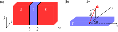
The considered S/F/S Josephson junction consists of two semi-infinite superconducting regions ( and ), which are weakly coupled by a ferromagnetic link with thickness . The system is schematically shown in Fig. 1(a).
At the flat interfaces between the different parts of the system, ultrathin tunneling barriers introduce potential and spin-orbit coupling (SOC) scattering. To compute the (dc) Josephson current flowing across the Josephson junction, we generalize the Furusaki-Tsukada technique Furusaki and Tsukada (1991), which allows us to relate the Josephson current to the Andreev reflection coefficients in the Bogoljubov–de Gennes scattering states for incoming quasiparticles from the left superconducting electrode. The addressed scattering states for quasiparticles with excitation energy are obtained by solving the stationary Bogoljubov–de Gennes equation De Gennes (1989); Žutić and Valls (1999, 2000)
| (1) |
where the single-particle Hamiltonian for electrons reads , whereas the one for holes is . The effective masses of quasiparticles are in the two superconducting regions ( and ) and in the ferromagnet (). Accordingly, the chemical potentials are given by and . The ferromagnetic material is described by the Stoner band model with the exchange energy gap . The magnetization direction is determined by the unit vector [see Fig. 1(b)] and comprises the Pauli spin matrices. The potential and SOC scattering at the left (L) and right (R) interfaces are modeled by and , where and are the heights and widths of the deltalike barriers, respectively, while the effective interfacial spin-orbit fields and include both Rashba and linear Dresselhaus terms Žutić and Das Sarma (2004); Fabian et al. (2007), parametrized by and . Neglecting the proximity effect in the ferromagnetic layer, the superconducting pairing potential can be approximated by the steplike behavior (the accuracy of this approximation was discussed, for instance, by Likharev Likharev (1979) and Beenakker Beenakker (1997) earlier), where is the isotropic energy gap in the two -wave superconductors and is the macroscopic phase difference across the junction.
We first solve the Bogoljubov–de Gennes equation in the three regions of the Josephson junction separately to obtain the corresponding scattering states for the injection of electronlike and holelike quasiparticles from the left superconducting electrode. Since the wave vector parallel to the interfaces is conserved, we can substitute () in Eq. (1) to reduce the scattering problem to an effective one-dimensional description for the unknown states . For an incident electronlike quasiparticle with spin up from the left superconducting lead, the solutions of the reduced Bogoljubov–de Gennes equation in the three components of the junction are
| (2) | |||||
| (3) | |||||
and
with the BCS coherence factors
| (5) |
The -components of the wave vectors for electronlike (holelike) quasiparticles in the superconducting regions can be written as , whereas the spin-resolved wave vectors for electrons and holes in the Stoner ferromagnet with a spin parallel () or antiparallel () to the magnetization direction are as well as , respectively. Thereby, and denote the Fermi wave vectors in the superconducting and ferromagnetic constituents of the Josephson junction. The spinors for electrons and holes in the ferromagnetic region have the form and , both containing
| (6) |
The unknown scattering coefficients and in the given scattering states indicate normal reflection of the incoming electronlike quasiparticle at the left interface without and with a spin flip, respectively, while and are the corresponding spin-resolved Andreev reflection coefficients. Accordingly, transmission into the right superconductor as an electronlike or holelike quasiparticle with spin up or spin down is incorporated in the amplitudes , , , and . To attain these scattering coefficients, we apply the boundary conditions
| (7) | |||||
| (8) | |||||
| (9) | |||||
| (10) |
with
| (11) |
to the obtained scattering states and numerically solve the resulting linear system of equations for the scattering coefficients.
The Bogoljubov–de Gennes scattering states for the injection of an electronlike quasiparticle with spin down, as well as for incoming holelike quasiparticles with spin up or spin down from the left superconducting electrode are constructed in the same way.
Following the Furusaki-Tsukada technique Furusaki and Tsukada (1991), the (dc) Josephson current is given by
| (12) | |||||
where is the (positive) elementary charge, is the Boltzmann constant, denotes the contact area, and are the -components of the wave vectors for electronlike (holelike) quasiparticles in the superconductors (see above) after analytically continuing to [ with are the fermionic Matsubara frequencies]. As explained before, the scattering coefficient refers to the situation that an incoming electronlike quasiparticle with spin up is Andreev reflected as a holelike quasiparticle with the same spin at the left junction interface. Analogously, , , and are the Andreev reflection amplitudes for the other involved quasiparticle injection processes. The temperature dependence of the superconducting energy gap within the BCS theory is , with being the critical temperature of the superconductor and its energy gap at zero temperature. Finally, the two-dimensional integration over the in-plane wave vector is introduced to average over all possible directions of incoming quasiparticles.
For a numerical evaluation of Eq. (12), we use realistic values for the superconducting energy gap and the critical temperature of conventional superconductors, i.e., and [for instance Carbotte (1990), alloy has and ]. For the Fermi level in the ferromagnet, we take a typical value of . To compactify the analysis, we define dimensionless parameters: , where and are the Fermi wave vectors in the ferromagnetic and superconducting regions, determines the strength of the potential barrier at the left (right) interface, quantifies the spin polarization in the ferromagnet, and as well as parametrize the interfacial Rashba and Dresselhaus SOC at the left (right) interface. Since the Rashba SOC strengths in the Josephson junctions depend not only on the concrete combinations of ferromagnetic and superconducting materials, but also on the bands contributing to electrical transport, these parameters are typically unknown and have to be extracted from ab initio calculations Matos-Abiague and Fabian (2009). Therefore, we will treat as phenomenological parameters throughout this paper. Mismatches of the effective masses and the Fermi wave vectors in the superconducting and ferromagnetic constituents of the junction—the latter result from different charge carrier densities in the materials Žutić and Valls (2000)—are included in the dimensionless parameters and , respectively. Table 1 summarizes all used system parameters in a compact way.
| spin polarization in ferromagnet | |
| barrier strength at left interface | |
| barrier strength at right interface | |
| Rashba SOC at left interface | |
| Rashba SOC at right interface | |
| Dresselhaus SOC at left interface | |
| Dresselhaus SOC at right interface | |
| Fermi wave vector mismatch | |
| mismatch of effective masses |
In the following, we present numerical results for the Josephson current at low temperature . To simplify the discussion and illustrate the main points, we mostly suppose equal effective masses and Fermi wave vectors in all components of the Josephson junction, i.e., . The impact of Fermi wave vector or mass mismatch on the outcomes is analyzed in Sec. V.
III Reversal of Josephson current induced by changing the interlayer thickness
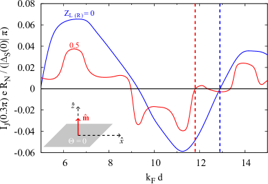
At first, we investigate the pure influence of changing the effective thickness of the metallic interlayer on the Josephson current flow across the regarded Josephson junctions. Figure 2 illustrates the calculated dependence of the Josephson current on for S/F/S model junctions in which neither interfacial Rashba nor Dresselhaus SOC are present, i.e., . For the spin polarization in the metallic interlayer, we choose a realistic value of , which would correspond in experiments to an iron layer, and the magnetization direction is aligned perpendicular to the junction interfaces. To evaluate the Josephson current numerically, the superconducting phase difference across the junction is set to a fixed value, for instance, . The qualitative results occurring at other superconducting phase differences are analog and not explicitly presented. Since present-day microfabrication techniques enable the experimental realization of ballistic metal/superconductor multilayer structures with highly transparent interfaces De Franceschi et al. (1998); Vas’ko et al. (1998); Wan et al. (2015), we concentrate on the cases of perfectly transparent junctions as well as weak symmetric tunneling barriers at the interfaces, modeled by and , respectively.
Even in junctions with perfectly transparent interfaces (), the Josephson current exhibits an oscillatory dependence on the effective interlayer thickness . Our model calculations show that, owing to these oscillations, the direction (sign) of the Josephson current flow can be reversed for certain values of , indicating transitions between and states. Since the oscillations in the - relation are solely caused by the exchange interaction in the central layer of the junctions, they characteristically appear only in S/F/S Josephson junctions and are absent in S/N/S Josephson junctions with a normal metal interlayer. As a consequence, states can emerge exclusively in S/F/S and not in S/N/S Josephson junctions.
To become more familiar with the physical concepts behind the - transitions Andreev et al. (1991); Demler et al. (1997), we have a closer look at the intermediate metallic region. Due to the proximity effect, spin-singlet Cooper pairs can leak from one superconductor across the interlayer into the other one, inducing superconducting correlations in the metal and generating a net supercurrent flow across the system. However, if the central region consists of a ferromagnet, the exchange interaction in the material opens an exchange energy gap between the spin up and spin down subbands. Consequently, the majority spin electron of the penetrating Cooper pair lowers its potential energy in the metallic interlayer, whereas that of the minority spin electron increases. Since the total energy of the electrons needs to be conserved, the kinetic part must compensate the changes of the potential energies and the Cooper pair acquires a finite center-of-mass momentum. This response of the transferred Cooper pairs to the spin-dependent potentials in the ferromagnet gives rise to spatial oscillations of the proximity-induced superconducting order parameter in the ferromagnetic layer Andreev et al. (1991); Demler et al. (1997). If the thickness of the metallic region is now comparable to half of the period of these oscillations, the superconducting order parameter may differ in sign at both junction interfaces and an additional intrinsic shift to the superconducting phase difference, entailing a transition from to states, may arise.
In the presence of weak interfacial barriers (), additional oscillations due to quasiparticle resonances (so-called geometrical oscillations Brinkman and Golubov (2000)) are superimposed on the oscillations originating from the exchange interaction. Nevertheless, the previous arguments concerning - transitions are still valid and crossovers between and states are again possible for certain values of effective interlayer thickness .
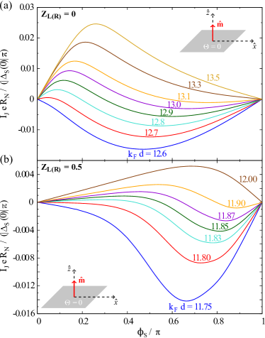
To characterize the transitions between and states further, the calculated dependence of the Josephson current on the superconducting phase difference (current-phase relation) is shown for different effective interlayer thicknesses close to one - transition in Fig. 3. In particular, the presented values of are chosen in the vicinity of the first to transitions in Fig. 2, indicated by the second sign changes of the Josephson current (see dashed lines in Fig. 2). All other system parameters are the same as before. Without interfacial tunneling barriers [; see Fig. 3(a)], increasing the effective interlayer thickness from to gives rise to a crossover from to states. In the transition region in between (), the coexistence of and states leads to nonsinusoidal variations of the current-phase relation. These outcomes are fully consistent with earlier obtained results of Radović and co-workers Radović et al. (2003). Similar characteristics were also predicted for - transitions controlled by changing the temperature Radović et al. (2003) or in the presence of inhomogeneous magnetization Bergeret et al. (2001b) in S/F/S junctions, as well as in S/F/c/F/S junctions with geometrical constrictions Golubov et al. (2002a); *Golubov2002alt. Moreover, a crossover between and states may also be achieved in dirty S/F/S Josephson junctions by reducing the interfacial transparency Buzdin and Baladié (2003); Golubov et al. (2004).
If moderate barriers [; see Fig. 3(b)] are present at both junction interfaces, the crossover points between and states are shifted to lower interlayer thicknesses (compare also to Fig. 2) and the region of coexisting and states () is nearly four times narrower than in the case of the perfectly transparent junction. The - transitions appearing at other values of lead to analog characteristics and are not explicitly analyzed.
IV Spin-orbit coupling induced 0- transitions and increase in critical current
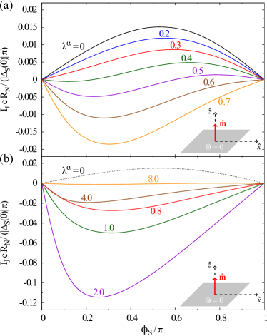
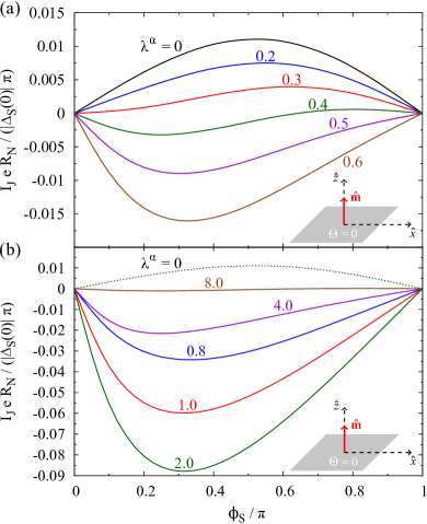
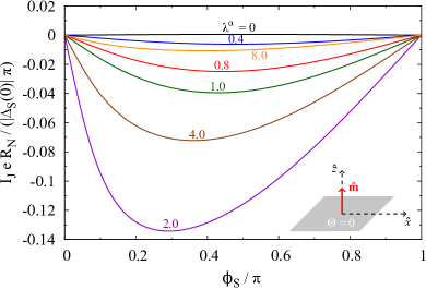
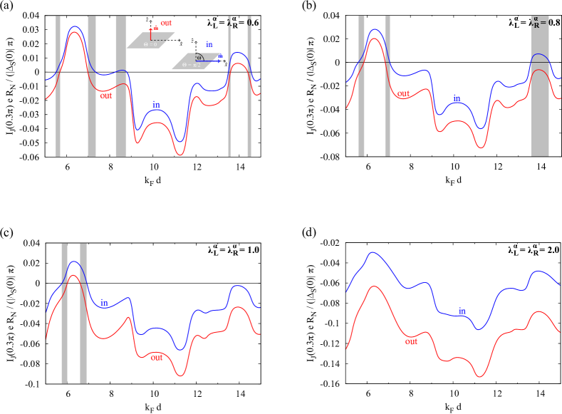
To study the impact of interfacial SOC on the Josephson current flow, the current-phase-relation for a realistic S/F/S Josephson junction is shown for various strengths of symmetric Rashba spin-orbit fields at the junction interfaces () in Fig. 4. The situation of antisymmetric Rashba spin-orbit fields () is rather unrealistic in real junctions and therefore not considered in this paper. The spin polarization in the ferromagnet is again chosen to be , its effective thickness is (these parameters would correspond in experiments to an iron interlayer with thickness as in iron Wang et al. (2003)), and the magnetization direction is oriented perpendicular to the ferromagnetic layer. To simplify the discussion, Dresselhaus SOC is absent () in all calculations throughout this section. Since reducing the interfacial transparency would not significantly change the qualitative features, we solely discuss the calculations for a junction with moderate interfacial barriers ().
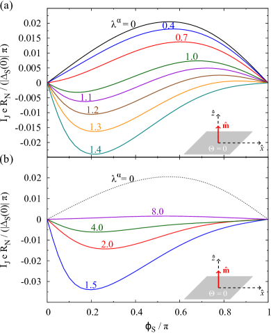
Without interfacial Rashba SOC (), the junction is in the state, in which the Josephson current approaches a sinusoidal dependence on . Increasing the strengths of the Rashba fields slightly, reverses the direction (sign) of the Josephson current flow [see Fig. 4(a)] and leads to a crossover from to states. Characteristic for the transition region between pure and states () is again a nonsinusoidal variation of the current-phase relation due to the coexistence of and states as we already explained for the - transitions controlled by altering the interlayer thickness in Sec. III. However, our calculations suggest that analogous physical effects may also be caused by modulating the strength of the interfacial Rashba fields, e.g., by means of an applied gate voltage Nitta et al. (1997); Koga et al. (2002), without the need to change the interlayer thickness of the Josephson junction.
Regarding the amplitudes of the Josephson current, the critical current becomes already at a moderate Rashba SOC strength of greater than in a junction without SOC. This is due to additional contributions to the Josephson current from spin-flip processes at the interfaces, enabled by the presence of spin-orbit fields. Increasing the Rashba SOC strength further [see Fig. 4(b)], the critical current first increases again, reaching its maximal value for ; the critical current there is one order of magnitude greater than the critical current in the absence of SOC. Nevertheless, we need to mention that SOC also introduces more scattering at the interfaces. This scattering starts to dominate at and reverses the increasing trend in the critical current.
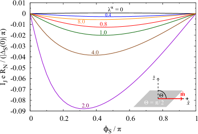
If the magnetization direction in the ferromagnetic layer is aligned parallel to the layer, the main qualitative physical characteristics do not change (see Fig. 5).
Increasing the Rashba SOC strength from still gives rise to a crossover from to states. Compared to the previously discussed case, in which the magnetization was oriented perpendicular to the ferromagnet, slightly stronger Rashba spin-orbit fields are required to induce - transitions in the junction with in-plane magnetization and also the region of coexisting and states is somewhat larger () than before [; see Fig. 4(a)]. A further increase of the Rashba SOC parameter again reflects the nonmonotonic dependence of the Josephson current on the SOC strength as its amplitudes first increase due to the formation of spin-triplet Cooper pairs, but finally decrease owing to the additional scattering introduced by SOC. However, when comparing the outcomes to the ones for perpendicular magnetization in Fig. 4, we observe that the critical current is remarkably smaller for all considered strengths of Rashba SOC and in-plane magnetization, suggesting that the generation of spin-triplet Cooper pairs becomes suppressed if the magnetization is parallel to the ferromagnetic layer. Nonetheless, it is important to stress here that the spin-triplet contribution to the Josephson current can still be dominant for certain strengths of the Rashba spin-orbit fields [e.g., for ; see Fig. 5(b)], significantly enhancing the critical current compared to the case without Rashba SOC (). This finding differs from earlier studies of diffusive lateral S/F/S Josephson junctions with SOC in the ferromagnetic region and in-plane magnetization Bergeret and Tokatly (2014), in which a long-range spin-triplet supercurrent component can only exist if both Rashba and Dresselhaus SOC are present.
Similar results are also obtained in S/F/S Josephson junctions with other values of interlayer thickness and spin polarization in the ferromagnet as we show in detail in Appendix A.
V Impact of Fermi wave vector or mass mismatch on the Josephson current
In this section we want to illustrate the influence of different effective masses or Fermi wave vectors in the superconducting and ferromagnetic constituents of the considered S/F/S Josephson junctions on the Josephson current flow. To quantify mismatches of the effective masses or Fermi wave vectors, we have introduced the dimensionless parameters and in the theoretical model presented in Sec. II.
First, we suppose equal effective masses of quasiparticles in all components of the Josephson junctions () and study the consequences of different Fermi wave vectors in the superconducting and ferromagnetic regions, which originate in real junctions from differing charge carrier densities in the materials Žutić and Valls (2000). Figure 6 shows the dependence of the Josephson current on the effective interlayer thickness for Josephson junctions with weak interfacial barriers () and spin polarization in the absence of both Rashba as well as Dresselhaus spin-orbit fields (). For the parameter , incorporating Fermi wave vector mismatch, we choose the values (no mismatch), (moderate mismatch), and (large mismatch), respectively. It is important to observe that an increase of the mismatch between the Fermi wave vectors in the superconducting and ferromagnetic materials of the Josephson junctions (which means decreasing ) does not change the oscillatory dependence of the Josephson current flow on the effective interlayer thickness qualitatively. Therefore, altering the interlayer thickness in such Josephson junctions can still provide a practicable way to reverse the direction (sign) of the Josephson current and induce a crossover between and states as already mentioned in Sec. III. Nevertheless, we observe here that Fermi wave vector mismatch shifts the transition points as a function of the effective interlayer thickness .
To investigate the effects of different effective masses in the superconductors and ferromagnet, the - relation is presented for the same junction as before, but with equal Fermi wave vectors () and differing effective masses in the superconducting and metallic parts in Fig. 7. Similarly to the discussion of Fermi wave vector mismatch, we also distinguish the situations of no mass mismatch (), moderate mismatch (), as well as strongly differing effective masses (). Again, the oscillatory dependence of the Josephson current on the effective interlayer thickness is still clearly visible, even at large mass mismatch. As we have already asserted for different Fermi wave vectors in Fig. 6, also an increase of mass mismatch (which means decreasing ) shifts the transition points, separating and states, to other values of the effective interlayer thickness .
From the presented calculations, we can conclude that the influence of Fermi wave vector or mass mismatch on the - relation is comparable to the effects of reduced interfacial transparency (see Sec. III). Similar effects of Fermi wave vector mismatch were predicted earlier by Radović and co-workers Radović et al. (2003).
At the end of this section, we briefly analyze the effects of Fermi wave vector or mass mismatch on the spin-orbit coupling induced - transitions predicted in Sec. IV. To find the most general features, we focus on two cases: in the first one (see Fig. 8), we assume equal effective masses () and moderate Fermi wave vector mismatch (), whereas in the second one (see Fig. 9), the Fermi wave vectors are equal () and moderate mismatch of the effective masses () is present. The other junction parameters are the same as for the junction discussed in Sec. IV, i.e., weak interfacial barrier strengths (), spin polarization , and effective interlayer thickness . In order to compare the results to the situation without any mismatches (see Fig. 4), we show the current-phase relation for weak Rashba SOC strengths in the vicinity of the induced - transitions [see Figs. 8(a) and 9(a)] and the one at stronger Rashba SOC [see Figs. 8(b) and 9(b)] separately (Dresselhaus SOC is always absent, ).
Interestingly, already rather weak Fermi wave vector mismatch () is sufficient to shift the transition point between and states to remarkably larger values of the Rashba SOC strength. Moreover, the region of coexisting and states is significantly larger in the presence of moderate Fermi wave vector mismatch [; see Fig. 8(a)] than in the junction without mismatches [; see Fig. 4(a)]. Regarding the amplitudes of the Josephson current, the maximal critical current occurs in the junction with Fermi wave vector mismatch at a slightly smaller Rashba SOC strength [; see Fig. 8(b)], but is by far not as large as in the junction without mismatches [compare to Fig. 4(b)]. Contrarily, in the case of moderate mass mismatch (), the spin-orbit coupling induced crossover between and states already emerges at extremely weak Rashba SOC strengths and the transition region with coexisting and states is quite narrow [; see Fig. 9(a)]. The maximal critical current in the presence of mass mismatch can flow across the junction at a Rashba SOC strength [see Fig. 9(b)] and is notably larger than in the junction with Fermi wave vector mismatch, but still not as large as in junctions without mismatches. Therefore, our calculations suggest that the enhancement of the Josephson current owing to the generation of spin-triplet Cooper pairs becomes maximal in junctions without Fermi wave vector or mass mismatch. Nevertheless, since the condition of perfectly matching Fermi wave vectors or effective masses in the superconducting and ferromagnetic materials of the Josephson junction is practically not achievable, the discussed effects associated with mismatch might play a quantitative role in experiments, although they do not change the qualitative characteristics.
VI Magnetoanisotropic Josephson current
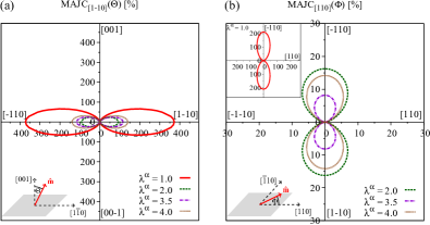
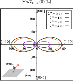
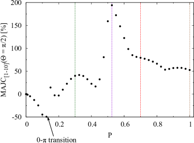
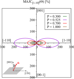
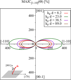
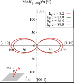
While the significant enhancement of the Josephson current due to the generation of spin-triplet Cooper pairs is already a first precursor for the presence of interfacial spin-orbit fields, magnetoanisotropic transport properties are a clear indication. Two configurations are important for investigating transport anisotropies in vertical junctions: out-of-plane, in which the magnetization direction is rotated along the polar angle in a plane perpendicular to the ferromagnetic layer, and in-plane, with changes of the azimuthal angle of in a plane parallel to the ferromagnetic layer. To quantify the anisotropies in both cases, we define the out-of-plane magnetoanisotropic Josephson current (MAJC) as
| (13) |
and the in-plane MAJC as
| (14) |
with being the critical current. In general, the out-of-plane MAJC depends on the azimuthal angle , but we choose as its reference.
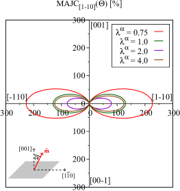
Numerical results for the angular dependencies of the out-of-plane and in-plane MAJC in a realistic Josephson junction with weak interfacial barriers (), spin polarization , and effective interlayer thickness are presented in Fig. 10. The strengths of the Dresselhaus spin-orbit fields are chosen to be rather moderate (), whereas the Rashba SOC parameters are varied from up to . To simplify the analysis, the Fermi wave vectors and effective masses in the superconducting and ferromagnetic parts are again assumed to be equal () in the following.
Similarly to earlier investigated TAMR Moser et al. (2007); Matos-Abiague and Fabian (2009) and MAAR Högl et al. (2015) effects, the interplay of ferromagnetism and the interfacial spin-orbit fields gives rise to marked magnetoanisotropies in the Josephson current flow. As a clear indication that the MAJC originates from this interplay, the characteristic symmetry of the spin-orbit fields at the interfaces is transferred to the angular dependencies of both the out-of-plane and in-plane MAJC.
Since the in-plane anisotropy stems from the interference of the interfacial Rashba and Dresselhaus spin-orbit fields Žutić and Das Sarma (2004); Moser et al. (2007); Matos-Abiague and Fabian (2009), the in-plane MAJC vanishes if one of the two fields is absent. In contrast, the out-of-plane anisotropy arises from the Rashba or Dresselhaus fields alone and is finite even in the presence of only one of the fields (see Appendix B), making out-of-plane MAJC measurements a robust probe for the presence of interfacial SOC, while the in-plane anisotropy is a sensitive probe of the interfacial symmetry. Owing to the complex interplay of the spin-orbit fields and ferromagnetism, the amplitudes of the out-of-plane and in-plane MAJC are very sensitive to changes of the Rashba SOC strength and vary nonmonotonically with respect to an increase of . Nevertheless, all calculated maximal MAJC values are giant compared to TAMR in similar junctions (for example, TAMR in Fe/GaAs/Au junctions is less than Moser et al. (2007)). The Josephson current flowing across the S/F/S junctions is extremely sensitive to rotations of the magnetization direction relative to the Rashba spin-orbit fields in the vicinity of - transitions. Therefore, especially giant MAJC amplitudes occur close to - transitions [e.g., in the out-of-plane and in the in-plane case at Rashba SOC strength ], allowing one to identify the vicinity of a - transition from MAJC measurements, without changing the thickness of the ferromagnetic layer in the controlling parameter. At greater Rashba SOC magnitudes, the junctions are in stable states and both the out-of-plane as well as the in-plane MAJC are remarkably suppressed.
In Appendix B we study the dependence of the MAJC on the spin polarization in the ferromagnet, covering both the Zeeman and exchange coupling magnitudes. It is worth to mention here that the predicted anisotropies are negligible in the Zeeman limit, which would correspond to exchange fields less than .
To investigate MAJC effects experimentally, a junction geometry comparable to the one of earlier TAMR experiments Moser et al. (2007) could be used. In such experiments, the magnetization direction of the ferromagnetic layer is typically rotated by an external magnetic field. In order to realize this in the regarded S/F/S Josephson junction, two aspects are of great importance. First, the thickness of the superconducting electrodes has to be in a range so that the applied magnetic field can penetrate into the central ferromagnetic region of the junction. On the other hand, one needs to ensure that the magnetic field does not suppress the superconducting properties in the left and right electrode of the junction. One possible way would be the usage of dysprosium magnets Betthausen et al. (2012), in which the magnetization can be oriented by an external field, but does not need the presence of the external field to remain in this position. As a consequence, the dysprosium layer in the Josephson junction could be premagnetized by applying an external magnetic field that rotates the magnetization into a certain direction. After switching off the field, the magnetic layer still shows a permanent magnetization in the chosen direction and the MAJC amplitudes can be measured without suppressing superconductivity. Moreover, transport through heterojunctions with contacts has been investigated very recently Wan et al. (2015). Owing to the large critical fields of these superconducting electrodes () compared to the external magnetic fields which are typically required to tilt the magnetization in the ferromagnet ( up to a few T), Josephson junctions with electrodes could also be of special interest to study the predicted magnetoanisotropic effects.
VII Reversal of Josephson current induced by changing the magnetization orientation
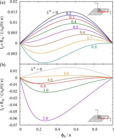
Following our above discussion on the huge magnetoanisotropies close to the - transitions, we now focus on the transitions themselves. We introduce the oriented critical current , given by the amplitude of the critical current with a positive sign for and a negative sign for states. The calculated dependence of on the polar magnetization angle and the effective interlayer thickness is depicted for realistic S/F/S Josephson junctions with weak interfacial barriers (), spin polarization , and moderate Rashba SOC strengths (Dresselhaus SOC is again absent) in Fig. 11(a).
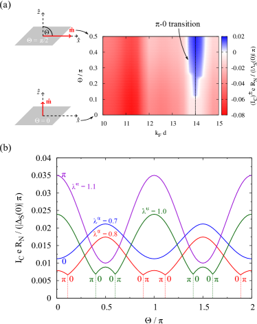
As long as the magnetization is aligned perpendicular to the ferromagnetic layer, the Josephson junctions are in stable states for all investigated values of []. However, close to , rotating the magnetization towards the plane reverses the supercurrent direction [], signifying to transitions. The impact of the Rashba SOC strength on these transitions is studied for a specific junction with in Fig. 11(b), which plots the dependence of the critical current on the magnetization polar angle for various Rashba SOC strengths . All other parameters are the same as in Fig. 11(a). The results in Fig. 11(a) correspond to the case of in Fig. 11(b), where the transition between and states now occurs as a dip in the - relation. The transition points are very sensitive to the Rashba SOC strength. For example, increasing the Rashba parameter from to shifts the first crossover between and states from to . Already for slightly weaker () or stronger () Rashba SOC, magnetization orientation controlled - transitions are absent. Instead, the junctions are in stable states in the former and stable states in the latter case for all regarded magnetization orientations. Similar phenomena are predicted to occur in lateral S/N/S junctions with Zeeman splitting and uniform Rashba coupling Yokoyama and Nazarov (2014); Yokoyama et al. (2014); Arjoranta and Heikkilä (2016). In Appendix C we provide a detailed analysis of the interlayer thickness dependence of the transitions.
Experimental realization of these predictions could follow the same way as suggested for MAJC measurements in the previous section.
VIII Summary
In this paper we studied the interplay of the Josephson effect, interfacial SOC, and exchange coupling in ballistic vertical S/F/S junctions. Our presented numerical calculations for realistic model junctions confirmed previous findings that changing the thickness of the metallic interlayer offers one practical way to manipulate - transitions. In the presence of interfacial Rashba SOC, we found that modulating the strength of these spin-orbit fields can not only significantly enhance the critical current due to the formation of spin-triplet Cooper pairs, but may also facilitate a crossover from to states, without the need to alter the thickness of the ferromagnetic layer. As a clear signature for the interfacial spin-orbit fields, we propose to investigate out-of-plane (Rashba) as well as in-plane (Rashba and Dresselhaus) magnetoanisotropies in the Josephson current flow. These anisotropies are giant compared to normal-state TAMR in magnetic tunnel junctions and even MAAR in single F/S junctions, especially in the vicinity of to transitions. Vice versa, we showed that these - transitions can also be controlled by solely rotating the magnetization direction in junctions with certain interlayer thicknesses and Rashba SOC strengths.
Acknowledgements.
This work was supported by DFG SFB Grant No. 689 and by the International Doctorate Program Topological Insulators of the Elite Network of Bavaria. This project has received funding from the European Union’s Horizon 2020 research and innovation programme under Grant agreement No. 696656. The authors gratefully acknowledge useful discussions with Farkhad Aliev and Christoph Strunk on experimental realizations of the presented results.Appendix A Impact of interlayer thickness and spin polarization on the Josephson current
In Sec. IV we analyze the spin-orbit coupling induced - transitions in a realistic model S/F/S Josephson junction. Here we qualitatively discuss the influence of the effective interlayer thickness and the spin polarization on these transitions. To simplify the analysis, we again assume equal effective masses () and Fermi wave vectors () in the superconducting and metallic regions of the regarded Josephson junctions. If not specifically indicated, the magnetization direction in the ferromagnet is aligned perpendicular to the junction interfaces.
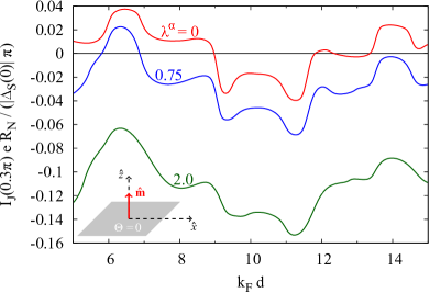
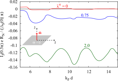
Figure 12 shows the calculated dependence of the Josephson current on the effective interlayer thickness for S/F/S Josephson junctions with weak interfacial barriers (), spin polarization , and for three different strengths of symmetric Rashba spin-orbit fields with , , and at a fixed superconducting phase difference of . The findings at other phase differences are comparable. As for the calculations discussed in Sec. IV, Dresselhaus SOC is absent (). The situation of perfectly transparent interfaces is again not explicitly considered since the qualitative tendencies are analog. Without SOC, we recover the results explained in detail in Sec. III. Owing to the exchange interaction in the ferromagnet, the Josephson current exhibits an oscillatory dependence on the effective interlayer thickness . For certain values of , these oscillations reverse the direction (sign) of the Josephson current, signifying - transitions. Also in the presence of interfacial Rashba SOC, the oscillatory dependence of the Josephson current on the effective interlayer thickness still clearly appears. Regarding the amplitudes of the Josephson current, we assert that an increase of the Rashba SOC strength to decreases the Josephson current for all regarded values of effective interlayer thickness and narrows the regions in which the junctions realize states (positive Josephson current) drastically. If the Rashba SOC strength gets increased to , the amplitudes of the Josephson current are lowered further and finally, the junctions are in states for all presented values of . This finding is quite notable since it suggests that the crossover from to states, caused exclusively by modulating the Rashba SOC strength as we have already analyzed in Sec. IV for one realistic model junction with constant thickness of the metallic link, is quite general and emerges also in junctions with other values of interlayer thickness. For completeness, we want to mention that a further enlargement of the Rashba SOC parameter again suppresses the absolute amplitudes of the Josephson current remarkably because of the additional scattering introduced by SOC at the junction interfaces (see also previous explanations).
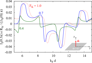
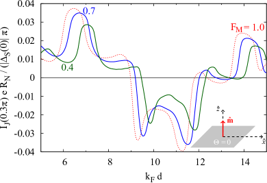
In S/F/S Josephson junctions, in which the interlayer consists of a half-metallic ferromagnet (spin polarization ), the qualitative outcomes (see Fig. 13) are similar to the preceding situation and hence, we only address a few interesting properties specifically. In junctions without interfacial Rashba SOC (), the amplitudes of the Josephson current become drastically damped with an increase of the effective interlayer thickness . This observation is a consequence of the density of states in half-metallic ferromagnets, in which only one spin subband is occupied at the Fermi level. The resulting insulating character for the other spin subband leads to a strong suppression of the transfer of spin-singlet Cooper pairs, consisting of two correlated electrons with opposite spin, across the metallic link and reduces the amount of supercurrent flowing in the system significantly. However, Keizer et al. reported one experiment Keizer et al. (2006) which predicts the existence of a measurable supercurrent component in the half-metallic link of diffusive Josephson junctions even over long length scales () compared to the coherence length in half-metallic ferromagnets. Since spin-singlet Cooper pairs cannot pass through the half-metallic layer, the observed Josephson current flow must be attributed to the generation of spin-triplet Cooper pairs via interfacial spin-flip processes at the junction interfaces Keizer et al. (2006); Zheng and Xing (2009), carrying the supercurrent across the metallic region. Within our model, spin-flip scattering at the superconductor/metal interfaces is enabled by the presence of spin-orbit fields. Indeed, the presented calculations reveal that increasing the Rashba SOC strength from to or enlarges the probability for the conversion of spin-singlet into spin-triplet Cooper pairs at the left interface and enhances the supercurrent flow remarkably. These tendencies are also visible in the current-phase relation for a superconductor/half-metallic ferromagnet/superconductor model junction with an effective interlayer thickness of , which is presented in Fig. 14. As in the junction with lower spin polarization (see Sec. IV), the maximal critical current appears for Rashba SOC strength . Its amplitude is now more than two orders of magnitude larger than in the absence of SOC, which again reflects the dominant role of spin-triplet Cooper pairs in Josephson junctions with half-metallic links. Moreover, modulating the Rashba parameter can also be identified as one possible way to control transitions between and states in superconductor/half-metallic ferromagnet/superconductor Josephson junctions. In comparison with the system in Sec. IV (spin polarization ), the crossover from to states is shifted to rather small SOC strengths () and the transition region, in which and states coexist, is significantly narrowed ().
Before finishing this part, we briefly want to discuss the calculated current-phase relation for the same junction as before, but with the magnetization direction aligned parallel to the ferromagnetic layer instead of perpendicular orientation (see Fig. 15). As we have already mentioned for the junction with lower spin polarization in Sec. IV, the contribution of the long-range spin-triplet supercurrent to the total Josephson current is remarkably smaller for in-plane magnetization than for perpendicular magnetization. Therefore, the critical current in the present junction is suppressed for all regarded strengths of the interfacial Rashba spin-orbit fields compared to the junction with perpendicular magnetization (see Fig. 14). However, increasing the Rashba parameter still gives rise to a transition from to states. The region of coexisting and states is shifted to slightly larger Rashba SOC strengths () than in the case of perpendicular magnetization ().
Appendix B Impact of interlayer thickness and spin polarization on magnetoanisotropic Josephson current
As explained in Sec. VI, magnetic anisotropy of the Josephson current flow across S/F/S junctions is a clear indication for the presence of interfacial spin-orbit fields. While the in-plane MAJC vanishes if only Rashba or Dresselhaus spin-orbit fields are present at the junction interfaces, the out-of-plane MAJC arises from Rashba or Dresselhaus SOC alone and can also be observed in the absence of one of the two spin-orbit fields, providing a reliable way to identify the presence of SOC. To stress this finding, we show the angular dependence of the out-of-plane MAJC for a model S/F/S Josephson junction with weak interfacial barriers (), spin polarization , effective interlayer thickness , and for various values of Rashba SOC strengths in Fig. 16 (Dresselhaus SOC is absent, i.e., ). In all calculations analyzed in the following, we assume equal effective masses and Fermi wave vectors in the superconducting and ferromagnetic materials () to simplify discussions. As expected, the out-of-plane MAJC is finite for all considered strengths of interfacial Rashba spin-orbit fields and reflects symmetry as a clear indication for the presence of interfacial SOC. Similarly to the junction considered in Sec. VI, the amplitudes of the out-of-plane MAJC depend sensitively on the Rashba SOC parameters and change nonmonotonically with increasing SOC strength. The maximal amplitudes of the out-of-plane MAJC can again reveal huge values—especially in the vicinity of - transitions—such as for . If the metallic link is composed of a half-metallic ferromagnet (spin polarization ; see Fig. 17), the nonmonotonic dependence of the out-of-plane MAJC on the strength of the interfacial Rashba spin-orbit fields still appears.
For all presented Rashba SOC parameters, the (maximal) amplitudes of the out-of-plane MAJC in the half-metallic case are smaller than in the junction with spin polarization . Furthermore, an increase of the Rashba SOC strength impacts the MAJC amplitudes in superconductor/half-metallic ferromagnet/superconductor Josephson junctions significantly only at stronger SOC (), whereas those in the previously discussed junction with lower spin polarization are extremely sensitive to a change of the SOC parameters even at rather moderate strengths of SOC.
To get a deeper insight, how the strength of the exchange splitting in the ferromagnetic region of the junctions impacts the magnetoanisotropy in the Josephson current flow, we present the maximal amplitudes of the out-of-plane MAJC [i.e., ] for interfacial Rashba SOC strength and different values of the spin polarization in the ferromagnetic layer in Fig. 18.
The other system parameters are the same as in the previous calculations. The maxima of the out-of-plane MAJC are extremely sensitive to a change of the spin polarization in the interlayer and vary nonmonotonically with increasing . The calculated MAJC values switch sign from negative to positive values at a spin polarization of , which is related to a crossover from to states. Noticeably huge MAJC ratios appear for rather large spin polarizations of (see dashed violet line in Fig. 18), whereas the anisotropy is nearly not measurable in junctions in which the spin polarization in the intermediate layer is extremely small (e.g., in S/N/S Josephson junctions in which an applied magnetic field gives rise to a comparatively small Zeeman splitting). The angular dependence of the out-of-plane MAJC in the regarded Josephson junctions is shown for four different spin polarizations, i.e., , , , and in Fig. 19.
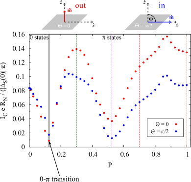
The outcomes again reveal symmetry, originating from the omnipresent interfacial Rashba spin-orbit fields, and confirm the nonmonotonic variation of the maximal MAJC amplitudes with an increase of the exchange splitting (spin polarization) in the intermediate region of the Josephson junctions (compare to dashed colored lines in Fig. 18). To understand the huge MAJC amplitudes at spin polarizations in the vicinity of , which signify huge magnetoanisotropies of the critical current, we have a closer look at the dependence of the critical current flowing across the Josephson junctions on the spin polarization in the ferromagnetic layer. At first, we regard the junctions in the absence of interfacial Rashba and Dresselhaus SOC, (see Fig. 20). The oscillatory dependence of the Josephson current, and therefore also the critical current, on the exchange splitting (spin polarization) in the interlayer is an important property of S/F/S Josephson junctions and was studied in detail earlier Radović et al. (2003); Yokoyama and Nazarov (2014); Yokoyama et al. (2014). Similarly to altering the interlayer thickness, the oscillations of the Josephson current induced by increasing the spin polarization in the ferromagnetic layer can result in - transitions for certain combinations of spin polarization, effective interlayer thickness, and barrier strengths. The transition points, separating and states, are indicated by the sharp dips in the - relation in Fig. 20. In particular for the chosen parameters, we predict the existence of four transitions between and states at spin polarizations of , , , and , respectively. The amplitudes of the critical current remarkably decrease at large spin polarizations since the transfer of spin-singlet Cooper pairs, which can solely carry the supercurrent in junctions without interfacial SOC, from one superconductor into the other one across the ferromagnetic part becomes drastically suppressed with an increase of the spin polarization. As the magnetoanisotropies in the Josephson current flow stem from the interplay of the interfacial spin-orbit fields and ferromagnetism, rotating the magnetization direction in the ferromagnet has no influence on the Josephson current flow as long as SOC is absent.

The situation becomes different if interfacial Rashba spin-orbit fields are present. Figure 21 shows the dependence of the critical current on the spin polarization in the interlayer for the considered Josephson junctions in the presence of interfacial Rashba spin-orbit fields (Dresselhaus SOC is still absent, i.e., ). We distinguish the situations in which the magnetization is aligned either perpendicular ( and ; abbreviated with “out”) or parallel ( and ; abbreviated with “in”) to the ferromagnetic layer. Compared to the junctions without interfacial SOC, increasing the exchange splitting (spin polarization) leads to only one crossover from to states at . The other three - transitions, which we predict by changing the spin polarization in the absence of Rashba SOC (see Fig. 20), are suppressed if Rashba spin-orbit fields with strength are present at the junction interfaces. Consequently, the junctions are now in stable states for all spin polarizations . Particularly for , this means that the presence of sufficiently strong Rashba SOC facilitates transitions from to states, confirming our previous findings that interfacial Rashba SOC might be used to manipulate - transitions effectively. By comparing the - relation to the calculated maximal MAJC amplitudes in Fig. 18, we assert that the huge MAJC ratios also mainly appear in that range of spin polarizations (), for which the Rashba spin-orbit fields cause transitions from states (see Fig. 20) to states (see vicinity of dashed violet line in Fig. 21). This observation suggests that the states, induced by interfacial Rashba SOC, are extremely sensitive to a change of the magnetization direction in the ferromagnetic layer so that rotating the magnetization from the “out” to the “in” configuration can give rise to huge relative anisotropies in the Josephson current flow close to the spin-orbit coupling induced - transitions as already mentioned in Sec. VI.
In order to analyze the role of the interlayer thickness, the angular dependence of the out-of-plane MAJC is shown for junctions with weak interfacial barriers (), spin polarization , and different values of the effective interlayer thickness in Fig. 22. The strengths of the Rashba spin-orbit fields at the junction interfaces are set to rather moderate values of and Dresselhaus SOC is again not present (). Similar considerations at other Rashba SOC parameters reveal analog characteristics. For all regarded parameter combinations, the out-of-plane MAJC shows a nonmonotonic behavior with respect to an increase of the interlayer thickness. Analogously to the preceding situations, the maximal amplitudes of the out-of-plane MAJC can again exhibit huge values as in junctions with an effective interlayer thickness of . The chosen parameters correspond to realistic junctions—for instance, to Josephson junctions with an iron interlayer, which has a thickness of (as in iron Wang et al. (2003))—so that the predicted huge MAJC ratios should also be observable in future experiments. If the metallic link is replaced by a half-metallic ferromagnet with spin polarization (see Fig. 23), the qualitative features of the out-of-plane MAJC do not change. Nevertheless, we observe that the maximal amplitudes of the MAJC get drastically suppressed compared to the previous case with spin polarization . Moreover, the MAJC amplitudes are less sensitive to changes of the interlayer thickness than in the preceding systems and are nearly independent of at .
The impact of changing the spin polarization in the ferromagnet or the interlayer thickness on the in-plane MAJC is similar to the one on the out-of-plane MAJC. Therefore, we do not present explicit calculations for the in-plane MAJC here.
Appendix C Impact of interlayer thickness on magnetization orientation controlled 0- transitions
We also examine in Sec. VII, whether the interplay of ferromagnetism and the present spin-orbit fields could offer another practical possibility to switch between and states by solely rotating the magnetization direction in the ferromagnet. From an experimental point of view, the magnetization direction could be changed by using Josephson junctions in which the interlayer consists of dysprosium magnets together with the application of an external magnetic field as explained in detail in Sec. VI. To get a first theoretical impression, we regard the dependence of the Josephson current on the effective interlayer thickness for a realistic system with spin polarization , moderate interfacial barriers (), and various strengths of Rashba SOC in the cases that the magnetization is aligned either perpendicular to the ferromagnetic layer ( and ; abbreviated with “out”) or in a plane parallel to the ferromagnetic layer ( and ; abbreviated with “in”) in Fig. 24. As before, the superconducting phase difference across the junction is set to a fixed value of , which is sufficient to deduce qualitative trends. Indeed, we assert that rotating the magnetization in the ferromagnetic layer from the “out” to the “in” configuration may reverse the direction (sign) of the Josephson current flow for certain combinations of the effective interlayer thickness and Rashba SOC strengths (see shaded regions in Fig. 24), which might be a first indication for the emergence of - transitions. It is important to stress that the intervals of , for which the Josephson current can switch its sign, probably signifying - transitions, depend very sensitively on the Rashba SOC strength as one can see by comparing the shaded areas in the different panels of Fig. 24, referring to different , respectively. Also the strength of the exchange splitting (spin polarization) in the ferromagnet may have a substantial impact on the magnetization orientation controlled - transitions. In Sec. VII, we present a more detailed investigation focusing on the Rashba SOC strength , for which changing the magnetization direction from the “out” to the “in” configuration can reverse the direction of the Josephson current flow in a comparatively wide range of interlayer thicknesses in the vicinity of [see shaded region around in Fig. 24(b)]. However, the results in Fig. 24 suggest that analog features can occur in junctions with other interlayer thickness or Rashba SOC strength likewise so that an experimental verification of our predictions is not necessarily restricted to the presented junction parameters.
References
- Eschrig (2011) M. Eschrig, Phys. Today 64, 43 (2011).
- Linder and Robinson (2015) J. Linder and J. W. A. Robinson, Nature Phys. 11, 307 (2015).
- Gingrich et al. (2016) E. C. Gingrich, B. M. Niedzielski, J. A. Glick, Y. Wang, D. L. Miller, R. Loloee, W. P. Pratt Jr, and N. O. Birge, Nat. Phys. 12, 564 (2016).
- Golubov et al. (2004) A. A. Golubov, M. Y. Kupriyanov, and E. Il’ichev, Rev. Mod. Phys. 76, 411 (2004).
- Buzdin (2005) A. I. Buzdin, Rev. Mod. Phys. 77, 935 (2005).
- Bergeret et al. (2005) F. S. Bergeret, A. F. Volkov, and K. B. Efetov, Rev. Mod. Phys. 77, 1321 (2005).
- Bulaevskii et al. (1977a) L. N. Bulaevskii, V. V. Kuzii, and A. A. Sobyanin, Pis’ma Zh. Eksp. Teor. Fiz. 25, 314 (1977a).
- Bulaevskii et al. (1977b) L. N. Bulaevskii, V. V. Kuzii, and A. A. Sobyanin, JETP Lett. 25, 290 (1977b).
- Buzdin et al. (1982a) A. I. Buzdin, L. N. Bulaevskii, and S. V. Panyukov, Pis’ma Zh. Eksp. Teor. Fiz. 35, 147 (1982a).
- Buzdin et al. (1982b) A. I. Buzdin, L. N. Bulaevskii, and S. V. Panyukov, JETP Lett. 35, 178 (1982b).
- Ryazanov et al. (2001) V. V. Ryazanov, V. A. Oboznov, A. Y. Rusanov, A. V. Veretennikov, A. A. Golubov, and J. Aarts, Phys. Rev. Lett. 86, 2427 (2001).
- Kontos et al. (2002) T. Kontos, M. Aprili, J. Lesueur, F. Genêt, B. Stephanidis, and R. Boursier, Phys. Rev. Lett. 89, 137007 (2002).
- Robinson et al. (2006) J. W. A. Robinson, S. Piano, G. Burnell, C. Bell, and M. G. Blamire, Phys. Rev. Lett. 97, 177003 (2006).
- Feofanov et al. (2010) A. K. Feofanov, V. A. Oboznov, V. V. Bol’ginov, J. Lisenfeld, S. Poletto, V. V. Ryazanov, A. N. Rossolenko, M. Khabipov, D. Balashov, A. B. Zorin, P. N. Dmitriev, V. P. Koshelets, and A. V. Ustinov, Nat. Phys. 6, 593 (2010).
- Yamashita et al. (2005) T. Yamashita, K. Tanikawa, S. Takahashi, and S. Maekawa, Phys. Rev. Lett. 95, 097001 (2005).
- Žutić and Das Sarma (2004) I. Žutić and S. Das Sarma, Rev. Mod. Phys. 76, 323 (2004).
- Fabian et al. (2007) J. Fabian, A. Matos-Abiague, C. Ertler, P. Stano, and I. Žutić, Acta Phys. Slovaca 57, 565 (2007).
- Ioffe et al. (1999) L. B. Ioffe, V. B. Geshkenbein, M. V. Feigel’man, A. L. Fauchère, and G. Blatter, Nature 398, 679 (1999).
- Mooij et al. (1999) J. E. Mooij, T. P. Orlando, L. Levitov, L. Tian, C. H. van der Wal, and S. Lloyd, Science 285, 1036 (1999).
- Devoret and Schoelkopf (2013) M. H. Devoret and R. J. Schoelkopf, Science 339, 1169 (2013).
- Likharev (1979) K. K. Likharev, Rev. Mod. Phys. 51, 101 (1979).
- Likharev (2012) K. K. Likharev, Phys. C 482, 6 (2012).
- Bychkov and Rashba (1984) Y. A. Bychkov and E. I. Rashba, J. Phys. C 17, 6039 (1984).
- Gmitra et al. (2013) M. Gmitra, A. Matos-Abiague, C. Draxl, and J. Fabian, Phys. Rev. Lett. 111, 036603 (2013).
- Dresselhaus (1955) G. Dresselhaus, Phys. Rev. 100, 580 (1955).
- Matos-Abiague and Fabian (2009) A. Matos-Abiague and J. Fabian, Phys. Rev. B 79, 155303 (2009).
- Brey et al. (2004) L. Brey, C. Tejedor, and J. Fernández-Rossier, Appl. Phys. Lett. 85, 1996 (2004).
- Moser et al. (2007) J. Moser, A. Matos-Abiague, D. Schuh, W. Wegscheider, J. Fabian, and D. Weiss, Phys. Rev. Lett. 99, 056601 (2007).
- Högl et al. (2015) P. Högl, A. Matos-Abiague, I. Žutić, and J. Fabian, Phys. Rev. Lett. 115, 116601 (2015).
- Oreg et al. (2010) Y. Oreg, G. Refael, and F. von Oppen, Phys. Rev. Lett. 105, 177002 (2010).
- Mourik et al. (2012) V. Mourik, K. Zuo, S. M. Frolov, S. R. Plissard, E. P. A. M. Bakkers, and L. P. Kouwenhoven, Science 336, 1003 (2012).
- Rokhinson et al. (2012) L. P. Rokhinson, X. Liu, and J. K. Furdyna, Nature Phys. 8, 795 (2012).
- Duckheim and Brouwer (2011) M. Duckheim and P. W. Brouwer, Phys. Rev. B 83, 054513 (2011).
- Nadj-Perge et al. (2014) S. Nadj-Perge, I. K. Drozdov, J. Li, H. Chen, S. Jeon, J. Seo, A. H. MacDonald, B. A. Bernevig, and A. Yazdani, Science 346, 602 (2014).
- Bergeret et al. (2001a) F. S. Bergeret, A. F. Volkov, and K. B. Efetov, Phys. Rev. Lett. 86, 4096 (2001a).
- Volkov et al. (2003) A. F. Volkov, F. S. Bergeret, and K. B. Efetov, Phys. Rev. Lett. 90, 117006 (2003).
- Halterman et al. (2007) K. Halterman, P. H. Barsic, and O. T. Valls, Phys. Rev. Lett. 99, 127002 (2007).
- Eschrig and Löfwander (2008) M. Eschrig and T. Löfwander, Nature Phys. 4, 138 (2008).
- Sun and Shah (2015) K. Sun and N. Shah, Phys. Rev. B 91, 144508 (2015).
- Bergeret and Tokatly (2013) F. S. Bergeret and I. V. Tokatly, Phys. Rev. Lett. 110, 117003 (2013).
- Bergeret and Tokatly (2014) F. S. Bergeret and I. V. Tokatly, Phys. Rev. B 89, 134517 (2014).
- Jacobsen and Linder (2015) S. H. Jacobsen and J. Linder, Phys. Rev. B 92, 024501 (2015).
- Yokoyama and Nazarov (2014) T. Yokoyama and Y. V. Nazarov, Europhys. Lett. 108, 47009 (2014).
- Yokoyama et al. (2014) T. Yokoyama, M. Eto, and Y. V. Nazarov, J. Phys.: Conf. Ser. 568, 052035 (2014).
- Arjoranta and Heikkilä (2016) J. Arjoranta and T. T. Heikkilä, Phys. Rev. B 93, 024522 (2016).
- Jacobsen et al. (2016) S. H. Jacobsen, I. Kulagina, and J. Linder, Sci. Rep. 6, 23926 (2016).
- Josephson (1962) B. D. Josephson, Phys. Lett. 1, 251 (1962).
- Josephson (1964) B. D. Josephson, Rev. Mod. Phys. 36, 216 (1964).
- Furusaki and Tsukada (1991) A. Furusaki and M. Tsukada, Solid State Commun. 78, 299 (1991).
- Radović et al. (2003) Z. Radović, N. Lazarides, and N. Flytzanis, Phys. Rev. B 68, 014501 (2003).
- Keizer et al. (2006) R. S. Keizer, S. T. B. Goennenwein, T. M. Klapwijk, G. Miao, G. Xiao, and A. Gupta, Nature 439, 825 (2006).
- De Gennes (1989) P. G. De Gennes, Superconductivity of Metals and Alloys (Addison Wesley, 1989).
- Žutić and Valls (1999) I. Žutić and O. T. Valls, Phys. Rev. B 60, 6320 (1999).
- Žutić and Valls (2000) I. Žutić and O. T. Valls, Phys. Rev. B 61, 1555 (2000).
- Beenakker (1997) C. W. J. Beenakker, Rev. Mod. Phys. 69, 731 (1997).
- Carbotte (1990) J. P. Carbotte, Rev. Mod. Phys. 62, 1027 (1990).
- De Franceschi et al. (1998) S. De Franceschi, F. Giazotto, F. Beltram, L. Sorba, M. Lazzarino, and A. Franciosi, Appl. Phys. Lett. 73, 3890 (1998).
- Vas’ko et al. (1998) V. A. Vas’ko, K. R. Nikolaev, V. A. Larkin, P. A. Kraus, and A. M. Goldman, Appl. Phys. Lett. 73, 844 (1998).
- Wan et al. (2015) Z. Wan, A. Kazakov, M. J. Manfra, L. N. Pfeiffer, K. W. West, and L. P. Rokhinson, Nat. Commun. 6, 7426 (2015).
- Andreev et al. (1991) A. V. Andreev, A. I. Buzdin, and R. M. Osgood, Phys. Rev. B 43, 10124 (1991).
- Demler et al. (1997) E. A. Demler, G. B. Arnold, and M. R. Beasley, Phys. Rev. B 55, 15174 (1997).
- Brinkman and Golubov (2000) A. Brinkman and A. A. Golubov, Phys. Rev. B 61, 11297 (2000).
- Bergeret et al. (2001b) F. S. Bergeret, A. F. Volkov, and K. B. Efetov, Phys. Rev. B 64, 134506 (2001b).
- Golubov et al. (2002a) A. A. Golubov, M. Y. Kupriyanov, and Y. V. Fominov, Pis’ma Zh. Eksp. Teor. Fiz. 75, 709 (2002a).
- Golubov et al. (2002b) A. A. Golubov, M. Y. Kupriyanov, and Y. V. Fominov, JETP Lett. 75, 588 (2002b).
- Buzdin and Baladié (2003) A. Buzdin and I. Baladié, Phys. Rev. B 67, 184519 (2003).
- Wang et al. (2003) J. Wang, D. Xing, and H. Sun, J. Phys. Condens. Matter 15, 4841 (2003).
- Nitta et al. (1997) J. Nitta, T. Akazaki, H. Takayanagi, and T. Enoki, Phys. Rev. Lett. 78, 1335 (1997).
- Koga et al. (2002) T. Koga, J. Nitta, T. Akazaki, and H. Takayanagi, Phys. Rev. Lett. 89, 046801 (2002).
- Betthausen et al. (2012) C. Betthausen, T. Dollinger, H. Saarikoski, V. Kolkovsky, G. Karczewski, T. Wojtowicz, K. Richter, and D. Weiss, Science 337, 324 (2012).
- Zheng and Xing (2009) Z. M. Zheng and D. Y. Xing, J. Phys. Condens. Matter 21, 385703 (2009).