High Precision Momentum Calibration of the Magnetic Spectrometers at MAMI for Hypernuclear Binding Energy Determination
Abstract
We propose a new method for absolute momentum calibration of magnetic spectrometers used in nuclear physics, using the time-of-flight (TOF) differences of pairs of particles with different masses. In cases where the flight path is not known, a calibration can be determined by using the TOF differences of two pair combinations of three particles. A Cherenkov detector, read out by a radio frequency photomultiplier tube, is considered as the high-resolution and highly stable TOF detector. By means of Monte Carlo simulations it is demonstrated that the magnetic spectrometers at the MAMI electron-scattering facility can be calibrated absolutely with an accuracy , which will be crucial for high precision determination of hypernuclear masses.
keywords:
Magnetic spectrometers, Cherenkov detectors, Radio Frequency Photomultiplier, Absolute calibration, Time of flight1 Introduction
The binding energy of the particle in the nuclear ground state gives one of the basic pieces of information on the -nucleus interaction. This binding energy is defined by:
| (1) |
where is the mass of the nucleus that is left in the ground state after the particle is removed, is the mass of the initial hypernucleus and is the mass of the . The binding energies have been measured in emulsion for a wide range of light () hypernuclei [1, 2, 3], exclusively from weak mesonic decays. The binding energies of light hypernuclei provide the most valuable experimental information to constrain various models of the Y-N interaction. Table 1, where the numbers are taken from Ref. [4], lists the results of the separation energies obtained from ab initio theoretical calculations using different Y-N interactions, along with the existing experimental results. In addition to the quoted statistical errors, the experiments also have systematic errors of about 0.04 MeV. It is seen that precise experimental measurements of the binding energies of light hypernuclei can discriminate between various models of Y-N interactions. In particular, accurate measurements of the separation energies of light -hypernuclei are a unique source of information on charge symmetry breaking in the -N interaction and in -hypernuclei [5, 6].
| Y-N | ) | ) | ) | ) | ) | ) |
| SC97d(S) | 0.01 | 1.67 | 1.20 | 1.62 | 1.17 | 3.17 |
| SC97e(S) | 0.10 | 2.06 | 0.92 | 2.02 | 0.90 | 2.75 |
| SC97f(S) | 0.18 | 2.16 | 0.63 | 2.11 | 0.62 | 2.10 |
| SC89(S) | 0.37 | 2.55 | Unbound | 2.47 | Unbound | 0.35 |
| Experiment |
In 2007 the use of magnetic spectrometers to measure precisely the momenta of pions from weak two-body decays of electroproduced hyperfragments was proposed for Jefferson Lab [7, 8]. A similar experimental program was started at the electron microtron in Mainz (MAMI) [9], where the first high resolution pion spectroscopy from decays of strange systems was performed by electron scattering off a target [10, 11, 12]. About 103 weak pionic decays of hyperfragments and hyperons were observed. The pion momentum distribution shows a monochromatic peak at MeV/c, corresponding to the unique signature for the two-body decay of hyper hydrogen , where the stopped inside the target. Its binding energy was determined to be (stat.) (sys.) MeV with respect to the mass.
We propose a new method for absolute calibration of magnetic spectrometers by using the time-of-flight (TOF) differences of pairs of particles. For example, by using the TOF difference of electrons and pions, a magnetic spectrometer can be calibrated at momenta if the flight path is known. In cases where the flight path is not known, a calibration can be determined by using the TOF differences of two pair combinations of three particles, e.g. of electrons, pions and electrons, kaons, or positrons, kaons and positrons, protons, or positrons, protons and positrons, deuterons at momenta around , respectively, where are the masses of pions, kaons and protons. A new, ultra-high resolution timing technique, based on Cherenkov radiation and the recently developed Radio Frequency Photomultiplier Tube (RFPMT) [13, 14], is considered. By means of Monte Carlo (MC) simulations it is demonstrated that the magnetic spectrometers at MAMI can be calibrated absolutely in the momentum range around 100 MeV/c with an error less than 0.01 MeV/c. This would consequently decrease the systematic error of the binding energy of hyper hydrogen to less than 0.007 MeV.
The decay pion experiment at MAMI is described in Sec. 2. The method of absolute calibration of magnetic spectrometers using TOF measurement of electrons and pions is presented in Sec. 3. In Sec. 4 and 5 the operational principles of the RFPMT are described. Sec. 6 is devoted to the ultra precise timing technique based on detection of Cherenkov radiation using the RFPMT. Demonstration of the absolute calibration of magnetic spectrometer SpekC at MAMI, by means of TOF difference measurements of one or two pairs of particles, using MC simulations, is presented in Sec. 7 and Sec. 8, respectively. In the first case it is assumed that the flight path is known; while in the second case TOF difference measurement of two pair combinations of three particles determine the absolute values of the flight path and momentum. Practical issues are discussed in Sec. 9.
2 The Hyperfragment Electroproduction Experiment at MAMI
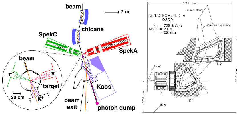
This experiment was carried out by the A1 Collaboration at the spectrometer facility at MAMI [15] (Fig. 1 left). A 1.508 GeV electron beam with a current of 20 A was incident on a 125 m thick target foil angled at 54 degrees with respect to the beam direction. Pions were detected with two high-resolution spectrometers (SpekA and SpekC), each having a quadrupole-sextupole-dipole-dipole, QSDD, configuration and a solid angle of 28 msr (Fig. 1 right). Vertical drift chambers (VDCs), situated close to the image plane (Fig. 1 right) were used for tracking, scintillation detectors for triggering and timing, and gas Cherenkov detectors for discrimination between electrons and pions. The VDCs are capable of measuring a particle track with effective position and angle resolutions of and mrad respectively. The spectrometers achieve a relative momentum resolution of and were operated at central momenta of 115 (SpekA) and 125 (SpekC) MeV/c with momentum acceptances of % (SpekA) and 25 % (SpekC). The tagging of kaons was performed by the Kaos spectrometer, positioned at zero degrees with respect to the electron beam direction. The central momentum was 924 MeV/c, covering a momentum range of % with a solid angle acceptance of msr.
3 Absolute Calibration of Magnetic Spectrometers
Absolute calibration of the magnetic spectrometers at MAMI can be realized by a TOF measurement of promptly produced pions and electrons [16]. Indeed, the TOF of pions or electrons of momentum over a flight path is:
| (2) |
| (3) |
| (4) |
| (5) |
From Eq. 4,5 and can be determined uniquely by measuring and . It is assumed that, for a fixed configuration of the system, the flight path and the magnetic rigidity of the spectrometer stay stable within a relative precision better than . A similar technique has been established for precise measurements of masses of exotic nuclei [17]. However, by using the RFPMT Cherenkov detector at MAMI we can determine absolute calibrations by measuring only the TOF differences for single and double pairs of particles. The details are described in Sec. 7 and Sec. 8.
4 The Radio Frequency Photomultiplier Tube
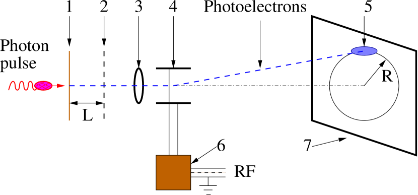
A schematic diagram of a RFPMT with a small size cathode is given in Fig. 2. Incident photons strike the photocathode, producing photoelectrons (PE) which are accelerated to 2.5 keV between the photo cathode and an electron-transparent electrode. They are then focused in an electrostatic lens and pass through the circular-sweep RF deflection system. PE’s passing through the RF deflector form a circle on the screen of the PE detector, where the time structure of the input photon signal is transformed into the spatial structure of the electron image on a circle.
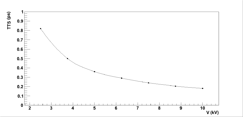
The detection of the RF analyzed PE’s is accomplished with a position sensitive (PS) PE detector. The time resolution for a single PE of this RF timing technique, , is determined by the transit time spread (TTS), , of PE’s in the electron tube and the time resolution of the RF deflector, . The transit time spreads were simulated by means of SIMION 8 software [18]. For an optimized tube geometry the calculated TTS as a function of applied accelerating voltage is shown in Fig. 3. In the simulations, PE energies were assumed to be distributed uniformly in the range 0-1 eV, while their initial directions were taken to be isotropic.
By definition the RF deflector time resolution is , where is a convolution of the size of the PE beam spot on the detector screen and the position resolution of the detector, and =2 is the scanning speed. Here is the radius of the circle and is the period of the RF field. For a properly designed 1 GHz RFPMT and PE detector with position resolution less than 0.1 mm, ps.
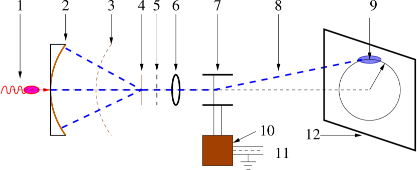
A schematic diagram of the RFPMT with an extended photocathode is given in Fig. 4. The primary photon pulse strikes the photocathode and produces PE’s. PE’s are accelerated in the “spherical-capacitor” region and focused on the crossover where they pass through a transmission dynode producing secondary electrons (SE) on both sides of the dynode. Low energy SE’s produced on the rear side of the transmission dynode are accelerated by the electron transparent electrode and enter into the electrostatic lens. SE’s passing through the RF deflector are deflected onto a circle on the screen of the PE detector and detected, similar to the case of the small-size cathode.
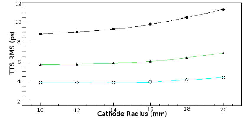
The TTS of PE’s at the crossover, simulated by means of SIMION 8 software, as a function of applied accelerating voltage between the cathode and the accelerating electrode are shown in Fig. 5. For an optimized large size photocathode RFPMT, the TTS can be as low as ps.
5 The RF Deflector and Anode Readout Architecture
The RF deflector consists of a pair of helical deflection electrodes [19]. These electrodes form a wire cavity with a quality factor . The resonant frequency can be fixed at the desired value by using a coaxial cavity or an additional variable capacitor. The sensitivity of the RF deflector at resonance frequencies is about 0.1 rad/W1/2 and a V (peak to peak) RF sine wave is sufficient to produce a scanning circle with a few cm radius and line-width on the PE detector plane. This new RF deflector can be operated in the 500-1000 MHz frequency range.
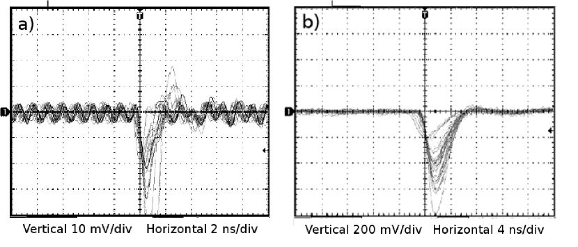
We have tested the operational principles of a PE detector consisting of a dual MCP chevron assembly, followed by an anode from which charge is collected. The ns rise time signal, generated by circularly scanned 2.5 keV electrons incident on the dual MCP chevron assembly and collected on the position sensitive resistive anode is shown in Fig. 6a. The signal after a preamplifier stage is displayed in Fig. 6b. The signal from the anode (Fig. 6a) consists of two parts: signals generated by 2.5 keV electrons and pickup from the RF driving the deflector. The single electron induced signals are an order of magnitude larger than the RF induced pickup and they can be processed by regular fast electronics. The few-ns integration time constant of the preamplifier stage is sufficient to suppress the RF background almost entirely.
Two readout methods have been devised to locate the position on the scanned circle: interpolation readout or pixel-by-pixel readout. Interpolation readout, using a circular resistive anode, needs only two readout channels and position is determined by applying charge-division or delay-line time difference techniques. However it can only bear a moderately high counting rate. For example with the dual MCP chevron assembly the anticipated maximum rate is about 1 MHz. A pixel-by-pixel readout anode will permit much higher counting rates [20] and pixel ASICs with 55 m resolution are readily available. A prototype resistive-anode RFPMT is under construction and will shortly be tested at an electron accelerator facility.
6 An Ultra Precise Timing Technique based on a Cherenkov Radiator and the RFPMT
qq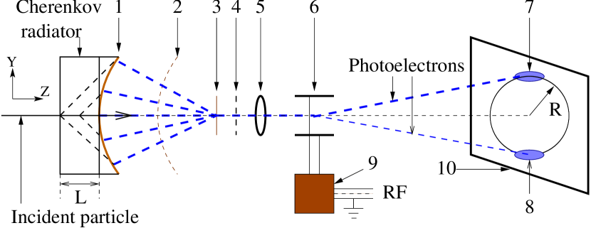
When a charged particle passes through a bar of transparent material, Cherenkov photons are emitted in a cone defined by the Cherenkov angle , where and is the refractive index. Cherenkov radiation is produced if the particle velocity and the flash duration of the Cherenkov radiation is ps [21]. The paths of the Cherenkov photons in a radiator are determined by (i.e. by the particle velocity) and the azimuthal angle [22]. These characteristics of the Cherenkov radiation, in combination with a ps-resolution photon detector, can produce an ultra high resolution timing detector. Here we will consider a Cherenkov TOF detector based on the RFPMT and a PbF2 radiator (). The following dominant factors have been taken into account in the MC simulations [13]:
-
1.
The time spread of Cherenkov radiation along the particle trajectory, over the thickness of the radiator, where Cherenkov photons were emitted uniformly along the particle track through the radiator.
-
2.
The transit time spread of Cherenkov photons due to different trajectories which, for individual photons, were determined according to and .
-
3.
The dependence of on the wavelength of the Cherenkov light, where we take a mean value and assume a Gaussian distribution for with .
-
4.
The timing precision of the photon detector, where a Gaussian distribution with ps has been used.
6.1 The Cherenkov TOF detector in a head-on geometry
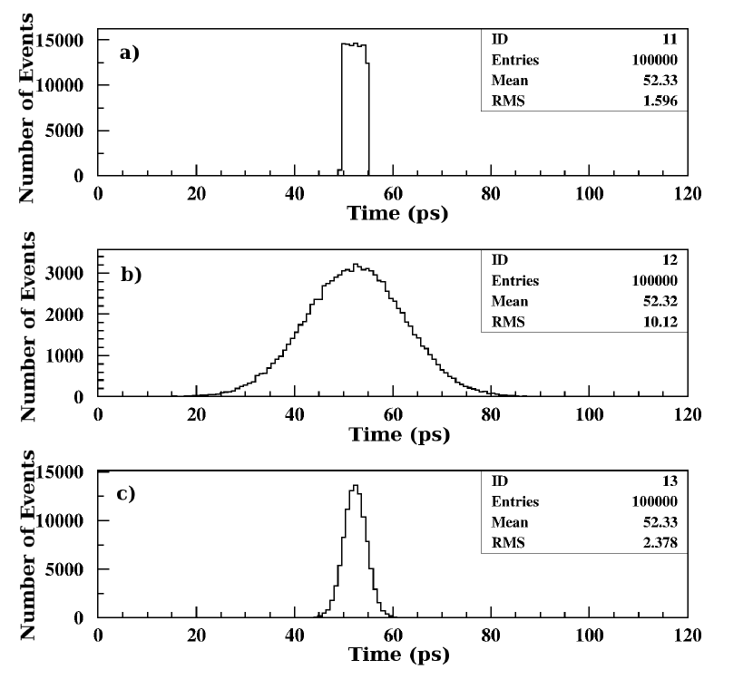
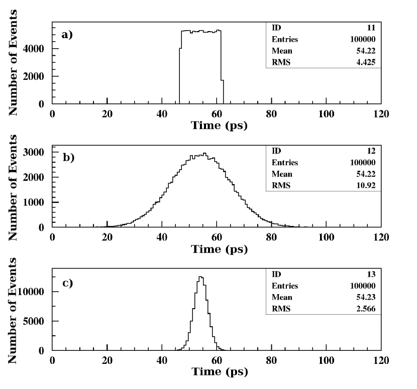
The Cherenkov TOF detector in a “head-on” geometry is shown schematically in Fig. 7 The incident particle produces Cherenkov photons in the radiator. These photons produce PE’s on the extended photocathode (1) which then pass through the tube as in Sec. 4. The expected time distribution of Cherenkov photons (a), single PE’s (b) and the mean of 20 PE’s (c), for normally incident 133 MeV/c pions and electrons on a PbF2 radiator (thickness cm) for a RFPMT with 10 ps time resolution, are displayed in Fig. 8 and Fig. 9, respectively. The time-zero, ps, is the time when a particle enters the radiator. The delay time of PE’s inside the RFPMT tube is assumed constant and has not been considered in these simulations. These simulations have demonstrated that such a Cherenkov detector can provide a time resolution ps FWHM. A similar result was obtained from a simulation using the GEANT-4 software package.
7 Absolute Calibration by a TOF Measurement of a Pair of Particles
We propose to use a Cherenkov detector in head on geometry for a TOF measurement of pions and electrons at MAMI. The detector will be located close to the focal plane of the spectrometer, with the RFPMT operated synchronously with the electron bunches [16, 23] produced by the MAMI accelerator. Both the bunch frequency (76.53 MHz) and the RFPMT drive frequency (612.25 MHz) would be derived as sub harmonics of the basic 2449 MHz operating frequency of the LINACs. In this case PE’s from Cherenkov radiation produced in the PbF2 radiator, by electrons and pions with the same momentum, will be located at different places of the scanning circle of the RFPMT (Fig. 7). The flight times of pions and electrons , from the target to the Cherenkov radiator can be expressed in terms of the period of the applied RF sinusoidal Voltage :
| (6) |
| (7) |
where , are integers and , are the coordinates of the PE produced by pions and electrons on the scanning circle of the RFPMT, relative to an arbitrary selected reference (see Fig. 7). The distributions of and were obtained by means of MC simulations for MAMI SpekC. The following factors have been taken into account:
-
1.
The timing accuracy of the RFPMT based Cherenkov detector, where a Gaussian distribution with ps has been used.
-
2.
The flight path of particles in the magnetic spectrometer: cm.
-
3.
The flight path spread, where a Gaussian distributions with cm has been used.
-
4.
The momentum distribution of electrons and pions, where we take MeV/c and assume a Gaussian distribution for the momentum spread with MeV/c.
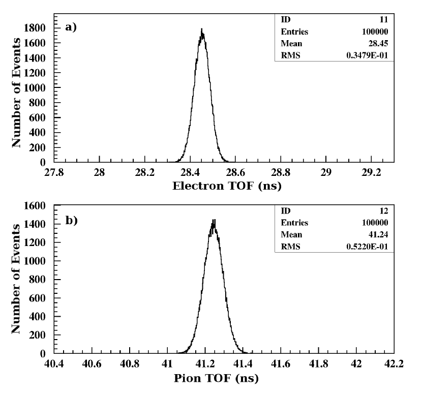
The obtained distributions of and are shown in Fig. 10. The histogram bin width is consistent with the expected resolving power of the RFPMT-Cherenkov detector.
The average times , and their difference can also be written:
| (8) |
| (9) |
| (10) |
The integers and were determined by using the parameters of the SpekC given above. For example, if ns we have and . Therefore, taking these parameters, can be determined from Eq. 10 by measuring . In this way the time delay in the RFPMT is canceled, because it is the same for photo electrons from pion and electron Cherenkov radiation. Rewriting Eq. 4 in the following form:
| (11) |
| (12) |
and solving Eq. 12 for gives:
| (13) |
where
| (14) |
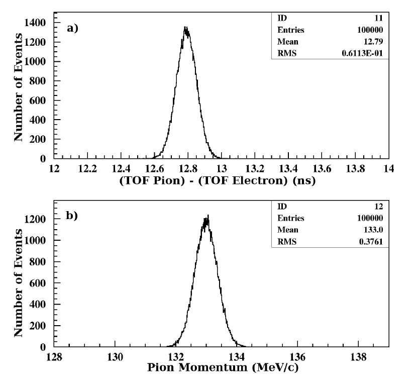
The flight time for pions, , and consequently the absolute value of momentum can be determined from Eq. 5. For example by using the mean values of the distributions displayed in Fig. 10 ( ps and ps) we obtain 132.99 MeV/c for the momentum . In principle we can also carry out this procedure by using the and event-by-event for every individual pion and electron pair, rather than taking their average values. The resulting distributions of and are displayed in Fig. 11. There are no significant differences in the values of obtained using either average or event-by-event methods, but in the case of an event-by-event analysis, any long term RFPMT time drifts are canceled [23].
| (MeV/c) | 132.0 | 132.5 | 133.0 | 133.5 | 134.0 |
|---|---|---|---|---|---|
| (ps) | 12955.4 | 12873.1 | 12791.4 | 12710.5 | 12630.4 |
| (MeV/c) | 132.004 | 132.504 | 133.004 | 133.504 | 134.004 |
The results of MC simulations for different values of initial momentum are presented in Table 2. From these simulations it follows that a 1 MeV/c difference in momentum produces a difference in ps over a flight path cm. Therefore must be measured to a precision of about 1.6 ps to give an absolute calibration of SpekC to better than 10 keV/c, which is achievable with the RFPMT. However the absolute value of would also require to be known to a precision of 853 cm 1.6 ps/12791.4 ps = 1.07 mm, which would be very difficult in practice.
8 Absolute Calibration by a TOF Measurement of a Triplet of Particles
The flight path uncertainty can be avoided if, in addition to the electron and pion, a third particle, e.g. a kaon, is detected. An absolute calibration of a magnetic spectrometer can be determined by measurement of differences in TOF of the two pair combinations e.g. pions and electrons, , and kaons and electrons, . Rewriting Eq. 4:
| (15) |
and deriving the following from Eq. 5
| (16) |
it follows that can be determined uniquely:
| (17) |
In this concept and, consequently , , and the absolute momentum , are determined by , and the masses of electrons, pions and kaons. In principle other combination of particles can be used, e.g. positrons, kaons and protons or positrons, protons and deuterons. Each combination of particles is effective in a given momentum range, where the momenta of at least 2 particles from three are non-relativistic. On the other hand they have to have enough velocity to produce prompt Cherenkov radiation. The effective momentum intervals are MeV/c for electrons, pions and kaons; MeV/c for positrons, kaons and protons; and MeV/c for positrons, protons and deuterons.
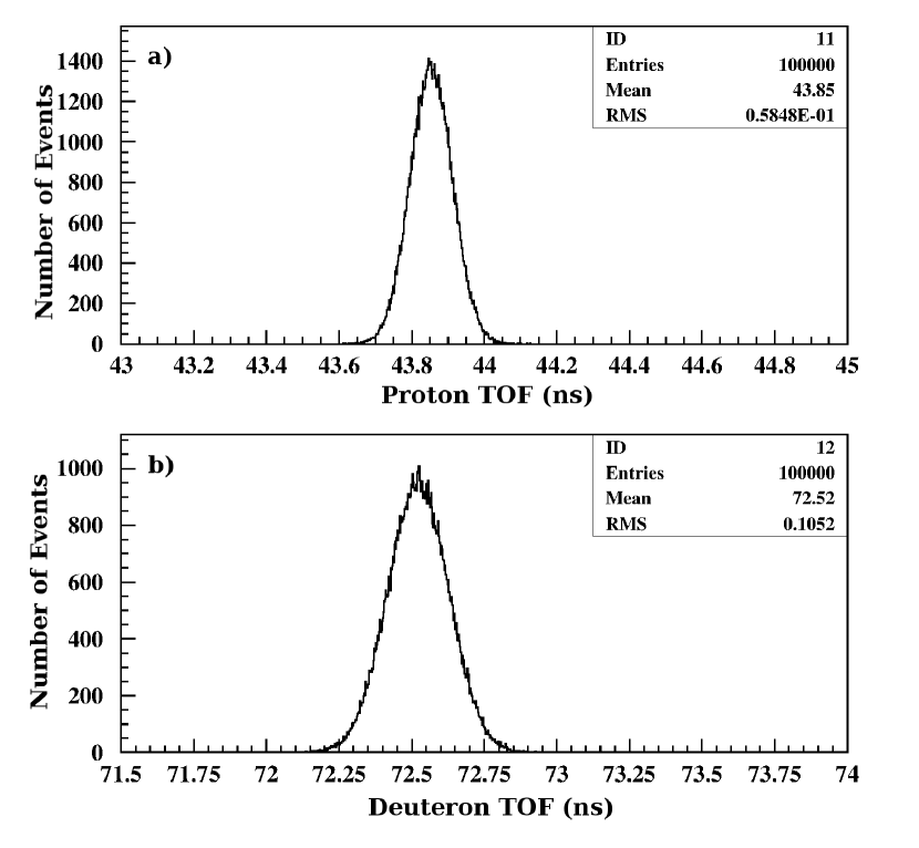
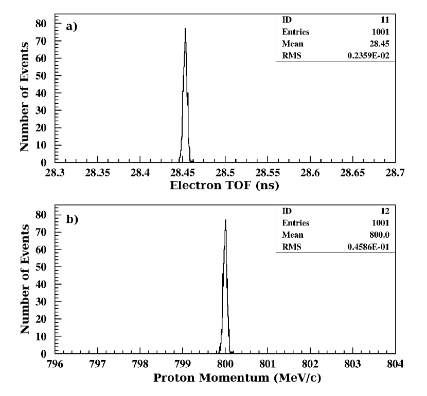
Since kaons in the previously mentioned momentum range will mainly decay over a 8.53 m flight path it may not be practical to use them. Alternatively one can use positrons, protons and deuterons to calibrate the magnetic spectrometer in the 800 - 1000 MeV/c momentum range and determine the central flight path . TOF distributions of protons and deuterons, obtained from MC simulations for 800 MeV/c are shown in Fig. 12. The average values of these distributions were used to determine their differences and calculate the absolute value of by using Eq. 17, where are replaced by .
The absolute value of determines the absolute calibration of and and the distributions of and obtained in this way are displayed in Fig. 13. In this simulation a synthetic rutile crystal (Titanium dioxide, TiO2, ), was considered as a radiator [24] in order to extend Cherenkov sensitivity to lower velocities. The value of determined in this way can then be used for absolute calibration of a magnetic spectrometer in the momentum range around 100 MeV/c by using the TOF difference of pions and electrons as described in Sec. 7. It is assumed that, for a fixed setup, the flight path length and other parameters of the spectrometer stay stable within a precision better than .
It is worth mentioning that Cherenkov radiation has already been registered by a circular-scan streak camera in Synchroscan mode [25]. Synchroscan operation of streak cameras is a regular timing technique for particle bunches at accelerators and the phase stability or time drift of the technique is 1-2 ps over periods of hours [26].
9 Practical Issues
As an example we consider the absolute calibration of SpekC at momenta around 133 MeV/c, which is close to the decay pion momentum of hyper hydrogen . If the flight path from the target to the Cherenkov detector is known, the calibration can be determined by TOF difference of electrons and pions. If the flight path from target to Cherenkov detector is not known we need three particles. As mentioned previously it may not be practical to use kaons due to the relatively long flight path of 8.53 m. Therefore we propose to use positrons, protons and deuterons to make a calibration at 800 MeV/c, which yields a value of with a precision better than 1 mm. Using this calibrated value of , and the TOF difference of pions and electrons, the magnetic spectrometer can be calibrated at a momentum range around 100 MeV/c, which is necessary for the decay pion experiment.
The Cherenkov detector will be mounted after the spectrometer’s drift chambers which sit close to the image plane of the spectrometer (see Fig. 1). Recently at MAMI the so-called single pulse operation, with few ps electron bunches every ns, was implemented and tested successfully up to average beam currents of 40 A. The bunch separation of ns follows from the use of a laser with a repetition frequency locked to the 32nd sub harmonic frequency of the MAMI standard microwave frequency of 2.449 GHz, that is 76.53 MHz. We can use this electron beam, but operate the RFPMT with a frequency locked to the 4th sub harmonic frequency of 2.449 GHz, which is 612.25 MHz. It is assumed that, by means of the tracking detectors, particles with well defined momentum can be selected, leading to a flight path spread mm.
The Cherenkov detector, readout by the RFPMT, will provide ns rise time electrical signals. These signals can be used, in a regular timing technique, to determine relative time differences between electrons and pions (or other particles) in SpekC and positrons/electrons in Kaos, with a precision of less than 1 ns [11]. This information will be used for identification of electrons and pions (or other particles) in SpekC.
Meanwhile charge comparison of the two signals from the RFPMT anode can be used to determine the position of PE’s on the scanning circle with a precision of about 50 m (see Fig. 7), equivalent to timing the PE’s with 1 ps precision, which would determine precisely the TOF differences of pions and electrons or any other pair of particles. This in turn is would determine the calibration of the spectrometer.
10 Conclusions
A new method for absolute momentum calibration of magnetic spectrometers employed in nuclear physics, using the time-of-flight (TOF) difference of pairs of particles is proposed. The situation of electrons and pions, for a known flight path, has been simulated at momenta around , where is the pion mass. Cases where the flight path is not known have been simulated by using the TOF differences of two pair combinations of three particles, in this case positrons, protons and positrons, deuterons at momenta close to , where is the proton mass. This yields a high-precision value of the flight path, which can then be fed back to the electron-pion case at lower momentum. A Cherenkov detector, read out by a radio frequency photomultiplier tube, has been simulated as the high-resolution and highly stable TOF detector. The Monte Carlo simulations predict that the technique, with the RFPMT operating at RF frequencies 500-1000 MHz, has a 10 ps resolution for single photons, and is capable of achieving 1 ps stability levels over periods of hours. The calculations predict that the magnetic spectrometers at the MAMI electron-scattering facility can be calibrated absolutely at momenta around 100 MeV/c with an accuracy , which will be crucial for precise determination of the binding energies of light hypernuclear systems.
Acknowledgments
This work was supported by the RA MES State Committee of Science, within the framework of research project 15T-2B206 and by the UK Science and Technology Facilities Council (Grant nos. STFC 57071/1 and STFC 50727/1).
References
- [1] W. Gajewski et al., A compilation of binding energy values of light hypernuclei, Nucl. Phys. B 1 (1967) 105-113.
- [2] G. Bohm et al., A determination of the binding-energy values of light hypernuclei, Nucl. Phys. B 4 (1968) 511-526.
- [3] M. Juric et al., A new determination of the binding-energy values of the light hypernuclei (), Nucl. Phys. B 52 (1973) 1-30.
- [4] H. Nemura et al., Ab initio approach to s-shell hypernuclei , , , and with a interaction, Phys. Rev. Lett. 89 (2002) 142504.
- [5] A. Gal, Charge symmetry breaking in hypernuclei revisited, Phys. Lett. B 744 (2015) 352.
- [6] D. Gazda and A. Gal, Ab initio calculations of charge symmetry breaking in the hypernuclei, Phys. Rev. Lett. 116 (2016) 122501.
- [7] A. Margaryan et al., Study of Hypernuclei by Pionic Decay, Letter of Intent LOI-07-001, Jefferson Lab. 2006.
- [8] A. Margaryan et al., Study of light hypernuclei by pionic decay at JLab, Experimental Proposal E-08-012 Jefferson Lab, 2007.
- [9] A. Esser et al., Prospects for hypernuclear physics at Mainz: from KAOS@MAMI to PANDA@FAIR, Nucl. Phys. A 914 (2013) 519-529.
- [10] A. Esser et al., Observation of hyperhydrogen by decay-pion spectroscopy in electron scattering, Phys. Rev. Lett. 114 (2015) 232501.
- [11] P. Achenbach et al., Experimental investigations of the hypernucleus , EPJ Web of Conferences 113, 07001, 2016.
- [12] P. Achenbach, Strange hadrons - strangeness in strongly interacting particles, Eur. Phys. J. ST 198 (2011) 307-327.
- [13] A. Margaryan et al., RF Cherenkov timing technique for high energy physics applications, Nucl. Instrum. Meth. A 595 (2008) 274.
- [14] A. Margaryan et al., Radio frequency picosecond phototube, Nucl. Instrum. Meth. A 566 (2006) 321.
- [15] K. I. Blomqvist et al., The three-spectrometer facility at the Mainz microtron MAMI, Nucl. Instrum. Meth. A 403 (1998) 263-301.
- [16] A. Margaryan. Radio frequency phototube, optical clock and precise measurements in nuclear physics, Preprint arXiv: 0910.3011 (2009).
- [17] A. Estrade et al., Time-of-flight mass measurements of neutron rich nuclides, 10th Symposium on Nuclei in the Cosmos, Michigan, USA, July 2008; Proceeding of Science, PoS (NIC) (2008) 184.
- [18] A. Margaryan et al., Picosecond photon detectors for the LHC, Acta Physica Polonica B Proc. Supliment 7 (4) (2014) 759.
- [19] L. Gevorgian et al., A radio frequency helical deflector for keV electrons, Nucl. Instrum. Meth. A 785 (2015) 175-179.
- [20] A. Margaryan et al., Single photon THz timer with radio frequency photomultiplier tube, Int. Workshop on New Photon-detectors, LAL, Orsay, France June 2012, http://pos.sissa.it).pos.sissa.it/archive/conferences/158/042/PhotoDet%202012_042.pdf.
- [21] I. M. Frank. Vavilov-Cherenkov Radiation. Theoretical Aspects. "Nauka" Moscow, (1988) 204-247 (In Russian).
- [22] B.N. Ratcliff, Imaging rings in Ring Imaging Cherenkov counters, Nucl. Instrum. Meth. A 502 (2003) 211.
- [23] A. Margaryan, Radio frequency phototube and optical clock: High resolution, high rate and highly stable single photon timing technique, Nucl. Instrum. Meth. A 652 (2011) 504-507.
- [24] V. P. Zrelov, Izluchenie Vavilova Cherenkova i ego priminenie v fizike visokikh energij, Chast II, ATOMIZDAT (1966) 70 (in Russian).
- [25] A. E. Huston and K. Helbrough, The Synchroscan picosecond streak camera system, Phil. Trans. R. Soc. Lond. A 298 (1980) 287-293.
- [26] K. Scheidt. Review of streak cameras for accelerators: features, applications and results. Proc. EPAC 2000, Vienna, Austria, (2000) 182, http://accelconf.web.cern.ch/accelconf/e00/PAPERS/WAYF202.pdf