Long-term stability test of a triple GEM detector
R. P. Adaka,
S. Biswasa∗,
S. Dasa,
D. Ghosalb,
S. K. Ghosha,
A. Mondalc,
D. Naga,
T. K. Nayakd,
R. N. Patrad,
S. K Prasada,
S. Rahaa,
P. K. Sahue,
S. Sahue,
and S. Swaine
a Bose Institute, Department of Physics and Centre for Astroparticle Physics and Space Science (CAPSS), EN-80, Sector V, Kolkata-700091, India
b Indian School of Mines, Dhanbad , Jharkhand-826 004, India
c Department of Physics, University of Calcutta, 92, APC Road, Kolkata-700 009, West Bengal, India
d Variable Energy Cyclotron Centre, 1/AF Bidhan Nagar, Kolkata-700 064, West Bengal, India
e Institute of Physics, Sachivalaya Marg, P.O: Sainik School, Bhubaneswar - 751 005, Odisha, India
∗E-mail: saikat@jcbose.ac.in, saikat.ino@gmail.com, saikat.biswas@cern.ch
Abstract
The main aim of the study is to perform the long-term stability test of gain of the single mask triple GEM detector. A simple method is used for this long-term stability test using a radioactive X-ray source with high activity. The test is continued till accumulation of charge per unit area 12.0 mC/mm2. The details of the chamber fabrication, the test set-up, the method of measurement and the test results are presented in this paper.
1 Introduction
Development of large area detectors based on Gas Electron Multiplier (GEM) technology is an advance area of research in the field of detector development for several upcoming High-Energy Physics (HEP) experimental projects [1]. For example A Large Ion Collider Experiment (ALICE) at the Large Hadron Collider (LHC) facility at CERN is upgrading it’s multi-wire proportional chamber based Time Projection Chamber (TPC) with GEM units, to cope with the foreseen increase of the LHC luminosity in Pb-Pb collisions after Long Shutdown 2 (LS2) [2, 3]. The Compressed Baryonic Matter (CBM) experiment at the future Facility for Antiproton and Ion Research (FAIR) in Darmstadt, Germany, will also use triple GEM detectors to instrument the muon detector MUCH (MUon CHamber) [4, 5, 6, 7, 8, 9, 10]. In line with the worldwide efforts, we have also taken an initiative in the experimental high-energy physics (EHEP) detector laboratories of different institutes in India, to carry on research and development with GEM detector prototypes. The GEM foils and other components of the detectors are obtained from CERN [11]. A triple GEM detector has been irradiated with Fe55 X-ray source while the anode current has been recorded continuously for a long period with Ar/CO2 gas in 70/30 volume ratio. During the whole period the ambient parameters such as temperature, atmospheric pressure and relative humidity are also measured and recorded continuously with a time stamp using a data logger developed in-house [12, 13]. Any large variation of the anode current indicates instability in the gain of the detector. The long-term stability test is performed measuring the anode current with the period of operation. The details of test results are presented in this article along with the details of the chamber fabrication test set-up and the method of measurement.
2 Description of the GEM detector prototype
A triple GEM detector prototype, consisting of 10 cm 10 cm standard stretched single mask foils, obtained from CERN is assembled in the clean room of RD51 laboratory [14, 15]. The drift gap, 2-transfer gaps and the induction gap of the chamber are kept as 3, 2, 2, 2 mm respectively. Although a triple GEM detector is built here, there is a provision of adding one more GEM foil to the detector to make it a quadrupole chamber required for ALICE TPC [3]. To keep this provision, two 10 mm thick G10 edge frames are used to make the gas enclosure. In such a system the Kapton window is eventually placed 11 mm above the drift plane. A voltage divider network is also built by resistors and a single negative high voltage (HV) channel is used to power the GEM chamber. The detector has a XY printed board (256 X-tracks, 256 Y-tracks) in the base plate and that works as the readout plane. Each of 256 X-tracks and 256 Y-tracks are connected to two 128 pin connectors. In each 128 pin connector a sum-up board (provided by CERN) is used. Total 4 sum-up boards are used in this detector. The Lemo output of the 4 sum-up boards are again summed and is directly connected by a short length Lemo cable to a 6485 Keithley Pico-ammeter to measure the total anode current.
3 Experimental set-up
Pre-mixed Ar/CO2 in 70/30 volume ratio has been used for the measurements. A constant gas flow rate of 3 l/h is maintained using a Vögtlin gas flow meter. The detector is biased through a resistive voltage divider chain. During the long-term test a constant HV of -4300 V is applied to the drift. The current through the divider chain is measured from the HV power supply. From the measured current and the known resistance value, the voltages across the different gaps and that across the GEM foils are calculated. At -4300 V the typical electric fields to the drift, transfer and induction gaps are found to be 2.4 kV/cm, 3.6 kV/cm and 3.6 kV/cm respectively and the voltage differences across the three GEM foils from top to bottom i.e. V1, V2 and V3 are 395 V, 360 V and 320 V respectively. A jig is made to place the Fe55 X-ray source on top of the detector. A place on the detector is marked to keep the source and to ensure that the source always irradiates a particular position of the detector. The collimator on the jig is made exactly same as the area of the source. The source diameter is 7.3 mm. The details of the measurements and the experimental results are described in Sec 4.
4 Experimental results
One crucial parameter for GEM technology to be used in modern age HEP experiment is the long-term stability of the gain of the detector. In that spirit, the following studies are performed for the GEM detector.
The HV to the GEM chamber is increased and the signals from the readout plane are counted for a fixed time interval. For each voltage setting the signals are counted with a Fe55 X-ray source and also without the source. For each voltage settings then count rate is calculated for the source only. Count rate is found to be increased with the increase of HV and reaches a plateau. At plateau the count rate is found to be 350 kHz.
The long-term stability of gain for the triple GEM detector is studied using a Fe55 source and measuring the anode current with and without source continuously [16, 17]. Similar type of measurements were carried out previously using 8 keV Cu X-ray generator and Sr90 beta radioactive source as referred in [16] and [17] respectively. At an interval of 15 minutes, the anode current with and without source are measured. Simultaneously the temperature (t in ), pressure (p in mbar) and relative humidity (RH in ) are also recorded using a data logger, built in-house, with a time stamp [12].
The output anode current due to the source is given by,
| (1) |
where is anode current due to source, is the measured anode current when the detector is irradiated by the Fe55 source and is the anode current without any source.
The absolute gain of the detector is calculated from the formula
| (2) |
where, is the rate of the X-ray, is the number of primary electrons and is the electronic charge. For each 5.9 keV Fe55 X-ray photon exposed in Ar/CO2 gas in 70/30 ratio is 212. Since in this measurement a Fe55 X-ray source is used and a Fe55 source has a finite half life of 2.7 years, the rate of the X-ray in the above equation is modified according to the following formula:
| (3) |
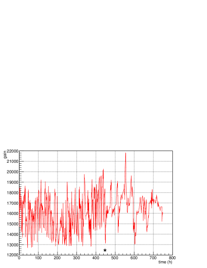
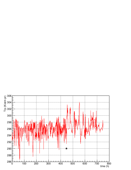
being 350 kHz, is the period of operation and is the half life of the Fe55 source. The variation of the measured gain is plotted as a function of total period of operation in Figure 1. It is well known that the gain of any gaseous detector depends significantly on T/p. The variation of the T/p as a function of the total period of operation is plotted in Figure 2, where T (= t+273) is the absolute temperature in Kelvin and p (p in mbar/1013) is in atmospheric pressure. The dependence of the gain (G) of a GEM detector on absolute temperature and pressure is given by [18]
| (4) |
where A and B are the parameters to be determined from the correlation plot.
The correlation plot, i.e. the gain is plotted as a function of T/p and fitted with a function
| (5) |
and is shown in Figure 3.
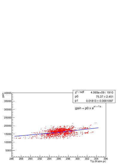
The values of the fit parameters A and B obtained, are 75.37 2.451 and 0.0181 0.0001 atm pr/K. Using the fit parameters, the gain is normalized by using the relation:
| (6) |
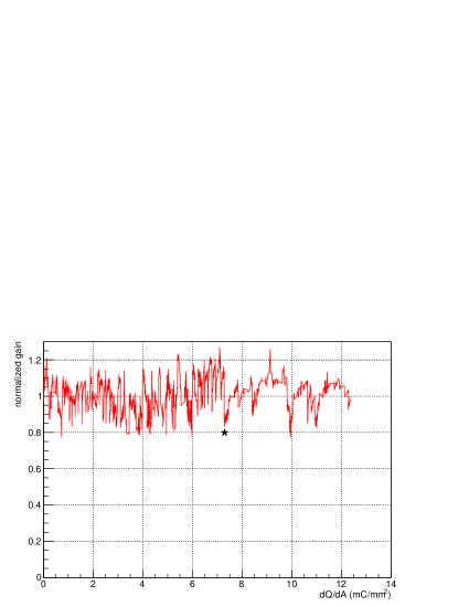
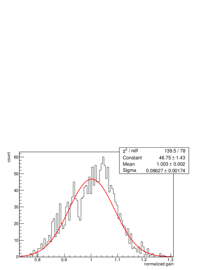
To check the stability of the detector with continuous radiation, the normalized gain is plotted against the total charge accumulated per unit irradiated area of the detector (that is directly proportional to time). To calculate the total charge accumulated, the average current of two time say and is taken and multiplied by the time interval . The total charge accumulated will be the sum of accumulated charge over all the intervals during every two adjacent readings. To get total charge accumulated per unit area, the total charge accumulated was divided by the area of the irradiated area. So mathematically the total charge per unit area is given by ]/A. Where A is the irradiated area. The normalized gain as a function of dQ/dA is shown in Figure 4. Although there is a fluctuation about 1 in the normalized gain value in Figure 4, but there is no steady decrease in the normalized gain. The distribution of the normalized gain fitted with a Gaussian function is shown in Figure 5. The mean of the Gaussian distribution has been found to be around 1.003 as shown in Figure 5 with a sigma of 0.086. In the first phase no ageing is observed even after operation of the GEM detector for about 450 hours or after an accumulation of charge per unit area 7.25 mC/mm2. After that a new gas cylinder of same mixture is used. This discontinuity is marked with a star (*) in Figure 4. In the second phase also there is no decrease in the normalized gain other than a fluctuation. In short no ageing is observed till accumulation of charge per unit area 12.0 mC/mm2.
5 Conclusions and outlooks
Triple GEM detector prototype is built and tested with a gas mixture of Ar/CO2 of 70/30 volume ratio. The long-term stability test of this detector is performed using Fe55 X-ray source. The gain is measured and normalized for the T/p effect. Only a fluctuation about 1 in the normalized gain is observed after T/p correction. No ageing is observed till an accumulation of charge per unit area 12.0 mC/mm2. From these results it can be concluded that triple GEM detector can safely be used in high-energy physics experiments where a long-term stability of the detector is an essential criterion.
6 Acknowledgement
The authors would like to thank the RD51 collaboration for the support in building and initial testing of the chamber in the RD51 laboratory at CERN. We would like to thank Dr. Eraldo Oliveri and Dr. Chilo Garabatos for his valuable discussions and suggestions during course of the work. R. P. Adak acknowledge the support UGC order no - 20-12/2009 (ii) EU-IV. This work is also partially supported by the research grant SR/MF/PS-01/2014-BI from Department of Science and Technology, Govt. of India.
References
- [1] F. Sauli, GEM: A new concept for electron amplification in gas detectors, Nuclear Instruments and Methods in Physics Research Section A 386 (1997) 531.
- [2] ALICE Collaboration, Technical Design Report for the Upgrade of the ALICE Time Projection Chamber, ALICE-TDR-016, CERN-LHCC- 2013-020, March 3, 2014.
- [3] Saikat Biswas, ALICE TPC upgrade for High-Rate operations, (To be published in the Proceedings of 7th International Conference on Physics and Astrophysics of Quark Gluon Plasma), [arXiv:1511.04988].
- [4] http://www.fair-center.eu/for-users/experiments/cbm.html
- [5] http://www.fair-center.eu/ .
- [6] CBM Progress report, 2008.
- [7] S. Biswas et al., Study of the characteristics of GEM detectors for the future FAIR experiment CBM, Nuclear Instruments and Methods in Physics Research Section A 718 (2013) 403.
- [8] S. Biswas et al., Measurement of the spark probability of a GEM detector for the CBM muon chamber (MuCh), Nuclear Instruments and Methods in Physics Research Section A 800 (2015) 93.
- [9] S. Biswas et al., Systematic measurements of the gain and the energy resolution of single and double mask GEM detectors, Nuclear Instruments and Methods in Physics Research Section A 824 (2016) 504.
- [10] R. P. Adak et al., Performance of a large size triple GEM detector at high particle rate for the CBM Experiment at FAIR),[arXiv:1604.02899v2].
- [11] GDD Group - CERN, http://gdd.web.cern.ch/GDD/ .
- [12] S. Sahu et al., Development of Data logger for atmospheric pressure, tempera- ture and relative humidity for gas-filled detector, Proceedings of the DAE Symposium on Nuclear Physics, Vol. 59, (2014), 876.
- [13] S. Sahu et al., Design and fabrication of a data logger for atmospheric pressure, temperature and relative humidity for gas-filled detector development, RD51-NOTE-2015-004, [arXiv:1507.03575v1].
- [14] http://rd51-public.web.cern.ch/rd51-public/ .
- [15] Supriya Das, Performance of a small triple GEM prototype, https://indico.cern.ch/event/334704/contributions/1727094/attachments/ 653571/898679/gem_test.pdf .
- [16] S. Biswas et al., Development of a GEM based detector for the CBM Muon Chamber (MUCH), 2013 JINST 8 C12002 doi:10.1088/1748-0221/8/12/C12002.
- [17] R.N. Patra et al., Characterisations of GEM detector prototype, Nuclear Instruments and Methods in Physics Research Section A 824 (2016) 501.
- [18] M.C. Altunbas et al., Aging measurements with the Gas Electron Multiplier (GEM), Nuclear Instruments and Methods in Physics Research Section A 515 (2003) 249.