Spacecraft observations and analytic theory of crescent-shaped electron distributions in asymmetric magnetic reconnection
Abstract
Supported by a kinetic simulation, we derive an exclusion energy parameter providing a lower kinetic energy bound for an electron to cross from one inflow region to the other during magnetic reconnection. As by a Maxwell Demon, only high energy electrons are permitted to cross the inner reconnection region, setting the electron distribution function observed along the low density side separatrix during asymmetric reconnection. The analytic model accounts for the two distinct flavors of crescent-shaped electron distributions observed by spacecraft in a thin boundary layer along the low density separatrix.
pacs:
Magnetic reconnection converts magnetic energy into kinetic energy of ions and electrons both during solar flare events krucker:2010 and reconnection observed in situ in Earth’s magnetosphere oieroset:2001 . Common for most theoretical models of reconnection is an emphasis on the dynamics of the electrons and their role in breaking the frozen in conditions for the electron fluid, permitting the magnetic field lines to change topology and release the stored magnetic stress in naturally occurring plasmas dungey:1953 . NASA’s new Magnetospheric Multiscale (MMS) mission is specially designed to address this question, as it can detect in situ possible mechanisms including electron inertia, pressure tensor effects, and anomalous dissipation for decoupling the electron motion from the magnetic field lines burch:2016b .
The identification of diffusion regions in the vast dataset now being recorded by MMS relies in part on numerical and theoretical models for distinct signatures of the reconnection region and the associated separatrix structure. Recent simulations of crescent-shaped electron distributions hesse:2014 ; chen:2016 have been proposed as a robust signature to find diffusion regions. The crescents are observed in two flavors: perpendicular and parallel to the magnetic field burch:2016 . The perpendicular crescent shapes are predicted theoretically in Refs. bessho:2016 ; shay:2016 , using 1D reasoning valid near the X-line, with electrons interacting strongly with a normal electric field .
Considering 2D geometries, here we provide a general derivation which accounts for the occurrence of both the perpendicular and parallel crescents. Only high-density (magnetosheath) particles with sufficient energy can cross the diffusion region to the low-density (magnetospheric) inflow region. Thus, the diffusion region acts like a Maxwell Demon allowing only the most energetic particles across. This provides an explanation for why the distributions are crescent shaped rather than filled in at lower energies. The requirement of having a sufficient energy is here quantified in terms of what we call the exclusion energy . As such, magnetosheath electrons with kinetic energies can access magnetic field lines on the magnetospheric side of the separatrix, exiting the region along the separatrix with nearly perfectly circular perpendicular motion. The parallel streaming and the absence of electrons with yields the parallel crescent-shaped distributions, and their origin is thus different from that proposed in Ref. burch:2016 . Contrary to the models applicable near the X-line bessho:2016 ; shay:2016 , we find that the perpendicular crescents along the separatrix are comprised of well magnetized electrons with nearly circular perpendicular orbit motion.
On October 16, 2015, NASA’s MMS mission had an encounter with an active reconnection region at the dayside magnetopause. The location of the encounter is sketched by the red rectangle in Fig. 1(a), as was established by the analysis in Ref. burch:2016 . Based in part on the recorded time series of the magnetic fields and ion flows, it was concluded that three of the four MMS spacecraft (MMS1, MMS2, and MMS3) passed the diffusion region on its northern side, while MMS4 passed it on the southern side. The four spacecraft all recorded similar structures, and here we consider data obtained by MMS3 and MMS4. The paths near the separatrix of these two spacecraft are sketched in Fig. 1(b), crossing from the low plasma density magnetosphere into the reconnection exhausts, in which the plasma is mainly provided by the much higher densities of the magnetosheath cassak:2007 .
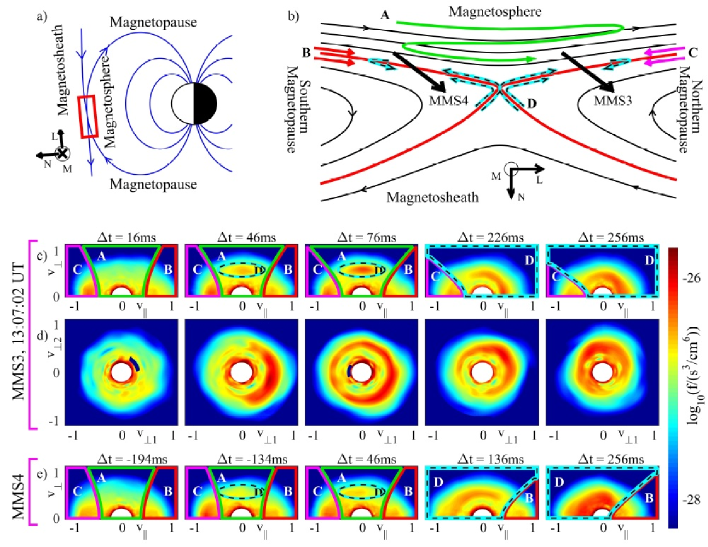
The distinct types of electron trajectories indicated in Fig. 1(b) are important to the structures in the electron distribution function. Passing electrons, labeled and , stream into the reconnection region along magnetic field lines, and do not change the signs of their magnetic field aligned (parallel) velocity as they pass through the region. Trapped electrons, illustrated by the green line labeled , have their bounce motion caused by trapping by the magnetic mirror force lavraud:2016 and the acceleration potential of Ref. egedal:2009pop . During the course of several bounce motions they convect slowly with the magnetic field lines towards the reconnection separatrix. The basis of this kinetic electron behavior is analogous to that of symmetric reconnection egedal:jan2005 ; egedal:2008jgr ; egedal:2013 , but for asymmetric reconnection trapping is most significant in the low density magnetospheric inflow egedal:2011popAsym . Trajectories of magnetosheath electrons near the separatrix (including their possible reflection back toward the X-line) are schematically illustrated by the cyan-black dashed lines labeled in Fig. 1(b).
The distribution functions displayed in Figs. 1(c-e) are calculated based on the full 3D electron data recorded by the Fast Plasma Investigation (FPI; pollock:2016 ) onboard MMS3 and MMS4 for selected time points relative to 13:07:02.000 UT. In the following we denote gyro-averaged distributions by . The distributions in Figs. 1(c,e) are obtained by first rotating the “raw” 3D electron distributions into a coordinate system aligned with the direction of the measured magnetic field. With , values of are then computed as the average of over the azimuthal gyroangle .
We first consider of MMS3 in Fig. 1(c) for ms. Corresponding to the orbit classification in Fig. 1(b), the regions of trapped electrons are labeled , while the regions of passing electrons are labeled by and . The trapped passing boundaries are obtained based on the local magnetic field and by estimating V by methods given in egedal:2010jgr . In agreement with Refs. egedal:2011popAsym ; graham:2016 , this is evidence that the strong parallel electron heating noted in Fig. 3(i) of Ref. burch:2016 is mainly due to energization by .
The distributions in Fig. 1(c) for ms are similar to that at ms, except that these include an additional feature within the trapped region. We mark this feature , as it is caused by energetic magnetosheath electrons penetrating across the separatrix to this location in the magnetospheric inflow. As MMS3 progresses across the separatrix, continues to change. At times ms, the regions of incoming passing electrons with (labeled in the ms plots in Fig. 1c) are now dominated by pitch angle mixed magnetosheath electrons streaming out along the separatrix from the reconnection region. These magnetosheath electrons are, naturally, also subject to parallel acceleration (deceleration) by and the mirror force, such that a fraction of these will be reflected back toward the diffusion region. Due to their larger density, the magnetosheath electrons dominate the full area in -space labeled , previously occupied by trapped electrons and region passing electrons.
The distributions in Fig. 1(d) are cuts through with . For ms complete rings in the -plane are clearly visible. Meanwhile, at ms, the ring is incomplete and only a crescent is observed. For this location, the recorded magnetic field is relatively strong, nT, corresponding to a Larmor radius for the typical crescent electrons of less than 2km. As shown in Fig. 1(e), the distributions recorded by MMS4 are similar to those of MMS3. However, the main and key difference (also discussed in Refs. burch:2016 ; shay:2016 ) is the reversed -sign of the -crescent for ms in Fig. 1(e). This is consistent with MMS4 crossing into the southern outflow, such that the passing electrons (region ) are eliminated in favor of magnetosheath electrons streaming southward, away from the diffusion region.
To explore the dynamics shaping the electron distribution function, we consider the trajectory in Fig. 2(a) calculated using the magnetic and electric fields of a fully kinetic simulation (to be further described below). This electron enters the reconnection region on a trapped trajectory originating in the magnetosheath. It then travels into the diffusion region and exits on the magnetopheric side of the separatrix. Only later does it reach the reconnection exhaust from the magnetospheric side. Apart from the electron’s brief encounters with the diffusion region, it is well magnetized with buchner:1989 , where is the radius of curvature of the magnetic field and is the Larmor radius of the electrons. On the other hand, the regions of chaotic unmagnetized electron dynamics in Fig. 2(a) are identified by the red areas where . Here the electron magnetic moments are not conserved, and their pitch angles are randomized le:2013 ; lavraud:2016 .
The above observations motivate a model for the electron dynamics as sketched in Fig. 2(b), where the electron motion outside the chaotic regions is described by the guiding center approximation. For 2D geometries, the canonical momentum in the out-of-plane direction of the guiding centers is a constant of the guiding center motion. Here is the out-of-plane component of the magnetic vector potential, with the reconnection X-line characterized by the value observed at the saddle point in the profile of . Upstream and close to the separatrix, is small so that , and it follows that guiding centers are locked to contours of constant .
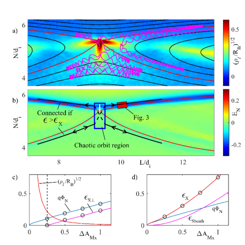
A quantitative condition required for magnetosheath electrons to jump to the magnetospheric inflow region is obtained through the use of the canonical momentum of the full electron motion. This quantity is a constant of motion throughout the cross section, including the chaotic orbit region. Variations in determine the orbit size and allow the Fig. 2(a) electron to move off its particular -contour by the amount . Thus, a magnetosheath electron entering the chaotic region on a guiding center trajectory characterized by can cross the separatrix only if the orbit permits a variation
| (1) |
This requires an initial minimum kinetic energy in the magnetosheath given by
| (2) |
Magnetosheath electrons passing through the diffusion region are energized by the strong electric field shown in Fig. 2(b), characterized by in Fig. 2(c), with evaluated along a cut starting at the X-line (short white line in Fig. 2(b)). The minimum kinetic energy is then given by , where the contribution dominates for (see Fig. 2(d)). The energization by is in the perpendicular direction, but for pitch angle mixing transfers a random fraction to the parallel direction for each electron. Meanwhile for , there is no pitch angle mixing such that the energization , identified in Fig. 2(c), remains in the perpendicular direction. Thus, any magnetosheath electron reaching sufficiently deep into the magnetospheric inflow will have a minimum perpendicular energy given by , acquired outside the region of pitch angle mixing.
We may now derive a simple model for the drift kinetic kulsrud:1983 guiding center distribution of magnetosheath electrons on the magnetospheric side of the separatrix. Consistent with the simulation, we assume that the chaotic region is characterized by a Maxwellian distribution . Using Liouville mapping of the phase density (), it follows that
| (3) |
where is the Heaviside step function. The heating by is included by evaluating at .
To validate the model in Eq. (3), we consider a kinetic simulation performed with the VPIC code bowers:2009 using asymptotic plasma parameters identical to those of Ref. burch:2016 . Here, however, the initial plasma current is carried by a modified Harris sheet roytershteyn:2012 . The reconnecting magnetic field and background temperatures vary as ( based on the magnetosheath density), and the density profile is adjusted to ensure magnetohydrodynamic pressure balance. The simulation is periodic in and has conducting boundaries in , with a total size of cells = . Separate populations of magnetosheath and magnetosphere particles with different numerical weights are loaded so that plasma mixing may be tracked over time daughton:2014 and so that both regions are resolved with 400 particles per cell per species. Other simulation parameters are a mass ratio of and (based on magnetosheath field and density).
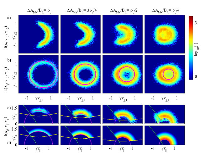
Particle distributions are computed at time , when reconnection has reached a quasi-steady state, and as indicated in Fig. 2(b), we use electron data collected away from the X-line along the separatrix. The data includes only electrons originating from the magnetosheath side and is collected as a function of for four locations within a narrow region reaching from the separatrix into the magnetospheric inflow. Here is the characteristic Larmor radius of a typical crescent electron (with relativistic momentum ). Fig. 3(a) shows the sequence of the full distributions integrated over the parallel velocity , revealing crescent-shaped and ring distributions qualitatively consistent with the MMS observations. Meanwhile, Fig. 3(b) shows the sequence of distributions also integrated over the parallel velocity , but now with the numerical electrons binned as a function of their guiding center locations. As such, is the distribution of guiding centers, defined without approximation through , where the direction of the vector is a function of the gyro-phase . The distributions are characterized by nearly perfect circles in a frame slightly off-centered from the origin by the EB-drift; in this frame these crescent electrons follow nearly perfectly circular perpendicular gyro-orbits, and is nearly independent of .
The gyro-averaged distribution of guiding centers in Fig. 3(c) are also compiled from the simulation particle data, where is evaluated in the frame of the EB-drift. The exclusion energies of Fig. 2(d) are shown by the magenta lines, accurately predicting the lower energy bound of the numerical distributions. The matching distributions in Fig. 3(d) are obtained from Eq. (3), based on values of , , and marked in Figs. 2(c,d). The combination of the exclusion energies reproduces the behavior of the -ring distributions with , evolving into crescent-shaped -distributions for locations very close to the separatrix, . We have verified that the model distribution in Eq. (3) is applicable along the separatrix of the full simulation domain, excluding only the region in Fig. 2(b) where the electrons are unmagnetized.
It is evident from Fig. 3(b-d) how rapidly increases with , practically eliminating all electron guiding centers for . However, the actual electron location is displaced from the guiding center . Depending on , this allows electrons to penetrate up to an additional into the magnetospheric inflow. As the separatrix is approached from the magnetopause inflow, the first magnetosheath electrons to be observed are those with placing their guiding centers closer to the separatrix. As such, the crescent distributions are a manifestation of the diamagnetic drifts associated with the rapidly changing pressure of the magnetosheath electrons at the magnetopause/exhaust separatrix.
In summary, we have extended the analysis of the MMS electron data of Ref. burch:2016 and shown that the observed parallel heating of the magnetospheric inflow is consistent with the trapping model of Refs. egedal:jan2005 ; egedal:2008jgr . Furthermore, the -crescent distribution encountered by MMS can be accounted for by extending the electron dynamics of the trapping model to include magnetosheath electrons penetrating into the magnetophere. Here the cutoff energy forbids electrons with insufficient diffusion region orbit size to reach into the magnetospheric inflow. The profile of depends strongly on the distance from the separatrix, where the chaotic region works like a Maxwell Demon, only letting the most energetic magnetosheath electrons pass to the magnetospheric side. The perpendicular crescent-shaped distributions are formed due to the spatial gradients imposed by . They are a direct manifestation of the diamagnetic drift of well magnetized magnetosheath electrons in a boundary layer with a width of about an electron Larmor radius all along the low density separatrix.
References
- (1) S. Krucker, H. S. Hudson, L. Glesener, S. M. White, S. Masuda, J. P. Wuelser, and R. P. Lin, “Measurements of the coronal acceleration region of a solar flare,” Astrophys. J., vol. 714, pp. 1108–1119, MAY 10 2010.
- (2) M. Øieroset, T. Phan, M. Fujimoto, R. P. Lin, and R. P. Lepping, “In situ detection of collisionless reconnection in the earth’s magnetotail,” Nature, vol. 412, pp. 414–417, JUL 26 2001.
- (3) J. Dungey, “Conditions for the occurence of electrical discharges in astrophysical systems,” Philosophical Magazine, vol. 44, p. 725, 1953.
- (4) J. L. Burch, T. E. Moore, R. B. Torbert, and B. L. Giles, “Magnetospheric Multiscale Overview and Science Objectives,” SPACE SCIENCE REVIEWS, vol. 199, pp. 5–21, MAR 2016.
- (5) M. Hesse, N. Aunai, D. Sibeck, and J. Birn, “On the electron diffusion region in planar, asymmetric, systems,” Geophy. Res. Lett., vol. 41, pp. 8673–8680, DEC 28 2014.
- (6) L.-J. Chen, M. Hesse, S. Wang, N. Bessho, and W. Daughton, “Electron energization and structure of the diffusion region during asymmetric reconnection,” Geophy. Res. Lett., vol. 43, pp. 2405–2412, MAR 28 2016.
- (7) J. L. Burch, R. B. Torbert, T. D. Phan, L. J. Chen, T. E. Moore, R. E. Ergun, J. P. Eastwood, D. J. Gershman, P. A. Cassak, M. R. Argall, S. Wang, M. Hesse, C. J. Pollock, B. L. Giles, R. Nakamura, B. H. Mauk, S. A. Fuselier, C. T. Russell, R. J. Strangeway, J. F. Drake, M. A. Shay, Y. V. Khotyaintsev, P. A. Lindqvist, G. Marklund, F. D. Wilder, D. T. Young, K. Torkar, J. Goldstein, J. C. Dorelli, L. A. Avanov, M. Oka, D. N. Baker, A. N. Jaynes, K. A. Goodrich, I. J. Cohen, D. L. Turner, J. F. Fennell, J. B. Blake, J. Clemmons, M. Goldman, D. Newman, S. M. Petrinec, K. J. Trattner, B. Lavraud, P. H. Reiff, W. Baumjohann, W. Magnes, M. Steller, W. Lewis, Y. Saito, V. Coffey, and M. Chandler, “Electron-scale measurements of magnetic reconnection in space,” SCIENCE, vol. 352, pp. 1189+, JUN 3 2016.
- (8) N. Bessho, L.-J. Chen, and M. Hesse, “Electron distribution functions in the diffusion region of asymmetric magnetic reconnection,” Geophy. Res. Lett., vol. 43, no. 5, pp. 1828–1836, 2016. 2016GL067886.
- (9) M. A. Shay, T. D. Phan, C. C. Haggerty, M. Fujimoto, J. F. Drake, K. Malakit, P. A. Cassak, and M. Swisdak, “Kinetic signatures of the region surrounding the x line in asymmetric (magnetopause) reconnection,” Geophy. Res. Lett., vol. 43, no. 9, pp. 4145–4154, 2016. 2016GL069034.
- (10) P. A. Cassak and M. A. Shay, “Scaling of asymmetric magnetic reconnection: General theory and collisional simulations,” Phys. Plasmas, vol. 14, OCT 2007.
- (11) B. Lavraud, Y. C. Zhang, Y. Vernisse, D. J. Gershman, J. Dorelli, P. A. Cassak, J. Dargent, C. Pollock, B. Giles, N. Aunai, M. Argall, L. Avanov, A. Barrie, J. Burch, M. Chandler, L. J. Chen, G. Clark, I. Cohen, V. Coffey, J. P. Eastwood, J. Egedal, S. Eriksson, R. Ergun, C. J. Farrugia, S. A. Fuselier, V. Genot, D. Graham, E. Grigorenko, H. Hasegawa, C. Jacquey, I. Kacem, Y. Khotyaintsev, E. MacDonald, W. Magnes, A. Marchaudon, B. Mauk, T. E. Moore, T. Mukai, R. Nakamura, W. Paterson, E. Penou, T. D. Phan, A. Rager, A. Retino, Z. J. Rong, C. T. Russell, Y. Saito, J. A. Sauvaud, S. J. Schwartz, C. Shen, S. Smith, R. Strangeway, S. Toledo-Redondo, R. Torbert, D. L. Turner, S. Wang, and S. Yokota, “Currents and associated electron scattering and bouncing near the diffusion region at Earth’s magnetopause,” Geophy. Res. Lett., vol. 43, pp. 3042–3050, APR 16 2016.
- (12) J. Egedal, W. Daughton, J. F. Drake, N. Katz, and A. Le, “Formation of a localized acceleration potential during magnetic reconnection with a guide field,” Phys. Plasmas, vol. 16, MAY 2009.
- (13) J. Egedal, M. Øieroset, W. Fox, and L. R. P., “In situ discovery of an electrostatic potential, trapping electrons and mediating fast reconnection in the earth’s magnetotail,” Phys. Rev. Lett., vol. 94, p. 025006, JAN 21 2005.
- (14) J. Egedal, W. Fox, N. Katz, M. Porkolab, M. Øieroset, R. P. Lin, W. Daughton, and D. J. F., “Evidence and theory for trapped electrons in guide field magnetotail reconnection,” J. Geophys. Res., vol. 113, p. A12207, MAR 25 2008.
- (15) J. Egedal, A. Le, and W. Daughton, “A review of pressure anisotropy caused by electron trapping in collisionless plasma, and its implications for magnetic reconnection,” Phys. Plasmas, vol. 20, JUN 2013.
- (16) J. Egedal, A. Le, P. L. Pritchett, and W. Daughton, “Electron dynamics in two-dimensional asymmetric anti-parallel reconnection,” Phys. Plasmas, vol. 18, OCT 2011.
- (17) C. Pollock, T. Moore, A. Jacques, J. Burch, U. Gliese, Y. Saito, T. Omoto, L. Avanov, A. Barrie, V. Coffey, J. Dorelli, D. Gershman, B. Giles, T. Rosnack, C. Salo, S. Yokota, M. Adrian, C. Aoustin, C. Auletti, S. Aung, V. Bigio, N. Cao, M. Chandler, D. Chornay, K. Christian, G. Clark, G. Collinson, T. Corris, A. De Los Santos, R. Devlin, T. Diaz, T. Dickerson, C. Dickson, A. Diekmann, F. Diggs, C. Duncan, A. Figueroa-Vinas, C. Firman, M. Freeman, N. Galassi, K. Garcia, G. Goodhart, D. Guererro, J. Hageman, J. Hanley, E. Hemminger, M. Holland, M. Hutchins, T. James, W. Jones, S. Kreisler, J. Kujawski, V. Lavu, J. Lobell, E. LeCompte, A. Lukemire, E. MacDonald, A. Mariano, T. Mukai, K. Narayanan, Q. Nguyan, M. Onizuka, W. Paterson, S. Persyn, B. Piepgrass, F. Cheney, A. Rager, T. Raghuram, A. Ramil, L. Reichenthal, H. Rodriguez, J. Rouzaud, A. Rucker, Y. Saito, M. Samara, J. A. Sauvaud, D. Schuster, M. Shappirio, K. Shelton, D. Sher, D. Smith, K. Smith, S. Smith, D. Steinfeld, R. Szymkiewicz, K. Tanimoto, J. Taylor, C. Tucker, K. Tull, A. Uhl, J. Vloet, P. Walpole, S. Weidner, D. White, G. Winkert, P. S. Yeh, and M. Zeuch, “Fast Plasma Investigation for Magnetospheric Multiscale,” SPACE SCIENCE REVIEWS, vol. 199, pp. 331–406, MAR 2016.
- (18) J. Egedal, A. Le, N. Katz, L. J. Chen, B. Lefebvre, W. Daughton, and A. Fazakerley, “Cluster observations of bidirectional beams caused by electron trapping during antiparallel reconnection,” J. Geophys. Res., vol. 115, p. A03214, MAR 23 2010.
- (19) D. B. Graham, Y. V. Khotyaintsev, C. Norgren, A. Vaivads, M. André, P.-A. Lindqvist, G. T. Marklund, R. E. Ergun, W. R. Paterson, D. J. Gershman, B. L. Giles, C. J. Pollock, J. C. Dorelli, L. A. Avanov, B. Lavraud, Y. Saito, W. Magnes, C. T. Russell, R. J. Strangeway, R. B. Torbert, and J. L. Burch, “Electron currents and heating in the ion diffusion region of asymmetric reconnection,” Geophysical Research Letters, pp. n/a–n/a, 2016. 2016GL068613.
- (20) J. Buchner and L. Zelenyi, “Regular and chaotic charged-particle motion in magnetotail-like field reversals .1. basic theory of trapped motion,” J. Geophys. Res., vol. 94, pp. 11821–11842, SEP 1 1989.
- (21) A. Le, J. Egedal, O. Ohia, W. Daughton, H. Karimabadi, and V. S. Lukin, “Regimes of the Electron Diffusion Region in Magnetic Reconnection,” Phys. Rev. Lett., vol. 110, MAR 28 2013.
- (22) R. M. Kulsrud, MHD description of plasma, vol. 1. North-Holland Publishing Company; New York, 2000.
- (23) K. Bowers, B. Albright, L. Yin, W. Daughton, V. Roytershteyn, B. Bergen, and T. Kwan, “Advances in petascale kinetic plasma simulation with VPIC and Roadrunner,” Journal of Physics: Conference Series, vol. 180, p. 012055 (10 pp.), 2009 2009.
- (24) V. Roytershteyn, W. Daughton, H. Karimabadi, and F. Mozer, “Influence of the lower-hybrid drift instability on magnetic reconnection in asymmetric configurations,” Phys. Rev. Lett., vol. 108, no. 18, p. 185001, 2012.
- (25) W. Daughton, T. Nakamura, H. Karimabadi, V. Roytershteyn, and B. Loring, “Computing the reconnection rate in turbulent kinetic layers by using electron mixing to identify topology,” Phys. Plasmas, vol. 21, no. 5, p. 052307, 2014.