Send correspondence to K. S. Karkare: 60 Garden St., MS
42, Cambridge, MA 02138, USA. E-mail: kkarkare@cfa.harvard.edu
Optical characterization of the BICEP3 CMB polarimeter at the South Pole
Abstract
Bicep3 is a small-aperture refracting cosmic microwave background (CMB) telescope designed to make sensitive polarization maps in pursuit of a potential -mode signal from inflationary gravitational waves. It is the latest in the Bicep/Keck Array series of CMB experiments located at the South Pole, which has provided the most stringent constraints on inflation to date. For the 2016 observing season, Bicep3 was outfitted with a full suite of 2400 optically coupled detectors operating at 95 GHz. In these proceedings we report on the far field beam performance using calibration data taken during the 2015-2016 summer deployment season in situ with a thermal chopped source. We generate high-fidelity per-detector beam maps, show the array-averaged beam profile, and characterize the differential beam response between co-located, orthogonally polarized detectors which contributes to the leading instrumental systematic in pair differencing experiments. We find that the levels of differential pointing, beamwidth, and ellipticity are similar to or lower than those measured for Bicep2 and Keck Array. The magnitude and distribution of Bicep3’s differential beam mismatch – and the level to which temperature-to-polarization leakage may be marginalized over or subtracted in analysis – will inform the design of next-generation CMB experiments with many thousands of detectors.
keywords:
Inflation, Gravitational waves, Cosmic microwave background, Polarization, BICEP1 INTRODUCTION
A period of accelerated exponential expansion in the early Universe, while a radical extrapolation from understood physics, naturally solves the flatness, horizon, and monopole problems of standard cosmology[1]. This inflationary period also explains the origin of structure by stretching quantum fluctuations to macroscopic scales. Inflation predicts perturbations to the metric in both scalars (density waves) and tensors (gravitational waves). Both types of perturbations affect the polarization of the cosmic microwave background (CMB) at last scattering[2]: scalars can only generate a gradient-type (-mode) pattern, while tensors can also generate a curl-type (-mode) pattern. Measurement of -mode power in the CMB at degree angular scales in excess of the expectation from gravitational lensing would be direct evidence for an inflationary period, and the amplitude of the signal – parametrized by , the tensor-to-scalar ratio – would indicate the energy scale of inflation.
Since 2006, the Bicep/Keck Array CMB polarization experiments have been mapping of low-foreground sky from the Amundsen-Scott South Pole Station. The telescopes are optimized to detect fluctuations at degree angular scales, and therefore use a compact, on-axis refracting optical system with the minimum aperture necessary to resolve the peak in the inflationary gravitational wave -mode spectrum. In 2014 we reported a detection of -mode power at degree angular scales at 150 GHz by Bicep2[3], which was quickly confirmed by data from the Keck Array[4]. Multifrequency maps are required to separate Galactic foreground emission (thermal dust at high frequencies and synchrotron at low frequencies) from the CMB signal. Using all available Planck and Wmap maps and the latest Keck Array maps at both 95 and 150 GHz, we find that the excess at 150 GHz is consistent with dust emission, and have constrained the tensor-to-scalar ratio to at confidence[5, 6]. To push this limit further – or achieve a detection of primordial -modes – we have deployed 220 GHz detectors in the Keck Array to measure dust at high precision, and have deployed Bicep3[7] at 95 GHz to probe deeply at a low-foreground frequency. For the 2016 observing season, Bicep3 was outfitted with a full complement of 20 detector tiles (2400 optically coupled detectors).
The Bicep/Keck Array telescopes measure polarization by differencing co-located, orthogonally polarized detector pairs[8]. Any mismatch in beam shape between the two polarizations will leak some of the bright CMB temperature signal into polarization. Temperature-to-polarization leakage is the most prominent instrumental systematic effect which may cause a false -mode signal and must be precisely characterized[9]. We have developed an analysis technique called deprojection[10] to marginalize over any false polarization signal which would arise from the coupling of the CMB temperature sky to a second-order expansion of the measured differential beam; however, the contribution from higher-order beam mismatch remains. In the Bicep2 final results, using high-fidelity far field beam maps we constrained the undeprojected residual contribution to the final -mode spectrum to an equivalent .
In these proceedings, we present an analysis of the far field beam response of the Bicep3 detectors observing in the 2016 season. In February and March of 2016, we obtained far field beam maps of all Bicep3 detectors in situ at the South Pole using a chopped thermal source in the far field of the telescope. These measurements serve several purposes: the array-averaged beam profile is used to smooth Healpix maps for simulations, the measured beam shapes offer a cross-check that the modes removed by deprojection correspond to actual beam mismatch and also allow for direct subtraction of the deprojection templates, and the beam maps are used in dedicated simulations to explicitly predict the residual -mode power after deprojection.
In Section 2 we review the optical design of Bicep3. In Section 3 we describe the far field beam measurement setup and the new chopped source constructed in 2016. In Section 4 we present two-dimensional Gaussian fits to each detector and characterize beamwidth, ellipticity, differential pointing, differential beamwidth, and differential ellipticity across the entire array. In Section 5 we coadd all beam measurements to obtain high signal-to-noise composite maps of individual beams, and use these beams to calculate the array-averaged beam response. In Section 6 we discuss the measured beam mismatch in the context of deprojection and the residual beam systematics levels achieved by Bicep2 and Keck Array. Three companion papers – a Bicep3 status update[11], Bicep3 detector performance[12], and measurements of Keck Array detector polarization angles with a dielectric sheet calibrator[13] – are also presented at this conference.
2 OPTICAL DESIGN
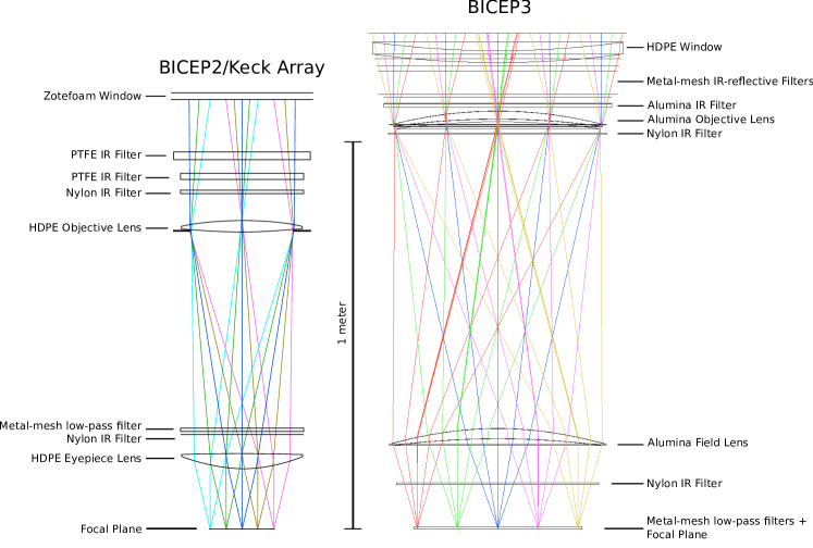
Like Bicep1, Bicep2 and Keck Array, Bicep3 is a compact, two-lens on-axis telecentric refracting telescope[14]. However, the aperture is twice as large as that of its predecessors ( mm vs mm), the field of view is larger ( vs ), and the optics are faster ( vs ). For observations at a wavelength of , the far field is at roughly .
Figure 1 shows a schematic of the optical system compared to that of Bicep2/Keck Array. Mounted directly on the detector modules are metal-mesh low pass filters with a cutoff at (120 GHz) to block out-of-band power. Two lenses, made of 99.6% pure alumina ceramic, perform the imaging; a cold Lyot stop skyward of the objective lens defines the aperture. The telescope housing, lenses, and aperture stop are all cooled to 4 K. The alumina lenses are anti-reflection coated with a mix of Stycast 1090 and 2850 epoxy tuned to the correct index of refraction ( for alumina at ), machined to the correct thickness and laser diced into patches to relieve mechanical stress from differential thermal contraction.
The aperture high-density polyethylene vacuum window is thick and anti-reflection coated with Teadit 24RGD. The large aperture allows over of infrared power to enter the cryostat, and the purely absorptive filtering used in Bicep2 and Keck Array would overload the Cryomech PT415 pulse tube; we therefore reject a majority of the loading with a stack of 10 metal-mesh IR-reflective filters mounted just below the receiver window at ambient temperature. Below these are flat absorptive filters: a thick alumina filter at 50 K above the objective lens, a thick nylon filter at 4 K above the field lens, and thick nylon filter at 4 K between the field lens and focal plane. There is an additional reflective metal mesh filter below the alumina filter at 50 K. The resulting IR load allows continuous operation of the pulse tube at K and hour hold time of the sub-Kelvin refrigerator.
To terminate far sidelobes in CMB observations, we install a co-moving absorptive forebaffle coated with a combination of Eccosorb HR-25/AN-75 and weatherproofed with Volara foam. The forebaffle is tall, in diameter, and intercepts radiation from the telescope boresight. The telescope is surrounded by a stationary reflective ground shield which redirects off-axis rays to cold sky; the geometry requires that a ray must diffract twice – around the forebaffle and ground shield – before it hits the ground.
3 FAR FIELD BEAM MEASUREMENT SETUP
The far field beam mapping setup for Bicep3 is very similar to that used for Bicep2 and the Keck Array; see the Beams paper[9] for additional details.
3.1 Flat Mirror and Thermal Chopped Microwave Source
Since the telescope is contained within its ground shield and can only tip down to from zenith, we use a flat mirror to redirect the beams over the ground shield and towards the thermal chopper (Figure 2, left panel). The 1.7 x 2.5 m aluminum honeycomb mirror is flat to 0.2 mm across its surface and is mounted at a angle, such that when the telescope is pointed at zenith, the beams are redirected towards the horizon (the source is above the horizon). The forebaffle is removed to provide room for the mirror.
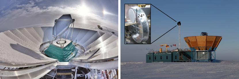
For the 2016 deployment season, we built two identical chopped thermal microwave sources so that Bicep3 and Keck Array could take far field beam map data simultaneously. These choppers consist of a rotating blade, an enclosure surrounding the blade, and a motor drive assembly to spin the blade. The blade is a composite material made from carbon fiber, low density foam, and honeycomb Nomex, coated with Eccosorb HR-10. The enclosure is made of a similar carbon fiber composite, coated with aluminum foil so that rays which do not terminate on the source aperture are reflected to cold sky (see the right inset of Figure 2). The source aperture is 24” in diameter, behind which is a flat mirror directed to zenith, so that the source chops between ambient ( K) and sky ( K). The entire assembly weighs 55 pounds. The right panel of Figure 2 shows the chopper mounted on a 40 ft high mast on the Martin A. Pomerantz Observatory, 211 meters away from Bicep3. The chopper can spin at a maximum of 9 Hz (18 Hz chop rate due to the two blades); for beam mapping in 2016 we operated at a 14 Hz chop rate. The aperture is sealed with HD-30 Zotefoam111HD-30 is also used for the Keck Array vacuum window and has transmission loss in our band. to prevent air turbulence from slowing down the blade. Compared to previous chopped thermal microwave sources deployed at South Pole, the 24” diameter chopper offers higher signal due to the larger aperture and lower noise due to the faster chop rate.
3.2 2016 Data Set
The far field beam maps presented in these proceedings were taken in February and March of 2016. Due to the comparatively high loading of the K source, beam maps are taken with the detectors on the aluminum superconducting transition222Our transition edge sensor (TES) detectors contain superconductors with different transition temperatures suitable for various loading conditions: titanium for CMB observations and aluminum for the higher loading in calibration measurements.. In this higher-loading configuration the sub-Kelvin refrigerator lasts for 12 hours. We scan across the source in azimuth rasters at per second, increasing the elevation by in between each scan. The scan speed was chosen so that at the fast detector sample rate (150 Hz) and source chop rate (14 Hz), multiple chop cycles would be recorded across the beam. The full field of view of the instrument is therefore covered in hours. To fill in the gap before the next fridge cycle, we additionally run “half” schedules which only cover the top, middle, or bottom of the focal plane. Schedules are evenly divided among five boresight angles: , , , , and . Consistency of beam maps across boresight angles offers a robust check on the repeatability of our beam measurements. Including both full and half focal plane configurations, we took a total of 77 beam mapping schedules. Once the data are taken, we demodulate the timestream data using a reference signal from the chopper and bin into maps with pixelization. The reflection off the mirror is handled with a pointing model that describes both the mount and the mirror.
4 GAUSSIAN BEAM PARAMETERS
4.1 Coordinate System and 2D Gaussian Fits
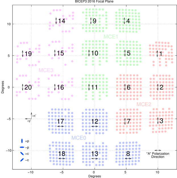
To facilitate comparison of beam parameters across measurements taken at multiple telescope orientations, we define a coordinate system similar to that used for Bicep2 and Keck Array beams analysis – see the Beams paper[9] for further details. Each pixel , consisting of two orthogonally polarized detectors, is at a location from the boresight. is the radial distance away from the boresight, and is the counterclockwise angle looking out from the telescope toward the sky from the ray, defined to be the great circle that runs along tiles 11/10/9 on the focal plane. For each pixel we then define a local coordinate system. The positive axis is along the great circle passing through which is an angle from the direction of the pixel, while the axis is along the great circle counterclockwise away from the axis. The coordinate system is then projected onto a plane at . This coordinate system is fixed to the instrument and rotates on the sky with the boresight rotation angle and the angle with which the receiver is clocked with respect to the line, or the drum angle ; for Bicep3, . In a simplified sense, to transform from mount coordinates to detector-centered coordinates, we flip the elevation axis to account for the mirror and rotate by to arrive at . All focal plane and beam map plots in these proceedings are rendered as the instantaneous projection of each beam onto the sky, with the same parity (viewing the projection from inside the celestial sphere) and orientation (with the axis pointing up and the axis pointing to the left); this is consistent with the conventions established in our other publications. Figure 3 shows the coordinate axes, the location of each nominally working beam, tile numbers and polarization axes, and the division of tiles into separate Multi-Channel Electronics (MCE) systems used to control the multiplexing and readout of the detectors.
Each beam is fit to a two-dimensional elliptical Gaussian model with six free parameters:
| (1) |
where is the location of the beam center, is the origin, is the normalization, and is the covariance matrix parametrized as
| (2) |
is the beamwidth and and are the ellipticities in the “plus” and “cross” directions respectively, such that an elliptical Gaussian with a major axis oriented along or would have a or ellipticity, and one with a major axis oriented diagonally would have a ellipticity (see Figure 3). Parametrization with (), while equivalent to the more common (), is more convenient because differential parameters are simple differences: , , , , and , where and refer to the orthogonally polarized detectors within a pair. These parameters directly scale the deprojection templates used to remove temperature-to-polarization leakage in analysis. Note that we do not use the absolute beam locations because of the complicated mirror model, instead obtaining beam centers from cross-correlation with the Planck CMB temperature maps.
In each of the 77 beam map schedules, we find the best fit , , , , and for every beam. Not all beams are covered in each schedule, and occasionally some detectors are not working normally even when they are covered. We then remove maps in which the fit failed, or in which only one of the or polarizations were working, so that the same number of measurements and detectors are used in per-detector and per-pair parameters. After cuts, the average pair has good measurements. Table 1 shows summary statatistics derived from these measurements. For each detector/pair, we take the median across the measurements as the best estimate of each parameter, and take half the width of the central 68% of the distribution of those measurements as the measurement uncertainty.333This statistic is relatively insensitive to outliers, and would equal for a Gaussian distribution of measurements. The characteristic uncertainty for an individual measurement – taken to be the median measurement uncertainty for all detectors/pairs across the array – is shown in the “Individual Measurement Uncertainty” column of Table 1.
To characterize the distribution of parameters, we also find the median across the focal plane (“FPU Median” column) and quantify the variation across the focal plane as half the width of the central 68% of the distribution of best estimates for each detector/pair (“FPU Scatter” column). Note that the “FPU Scatter” measures the spread of best-estimate parameters across the array and is not a measurement uncertainty.
| Parameter | FPU Median | FPU Scatter | Individual Measurement Uncertainty |
|---|---|---|---|
| Beamwidth (degrees) | 0.167 | 0.002 | 0.002 |
| Ellipticity plus (+) | 0.010 | 0.021 | 0.026 |
| Ellipticity cross () | -0.004 | 0.016 | 0.026 |
| Diff. X pointing (arcmin) | 0.03 | 0.13 | 0.05 |
| Diff. Y pointing (arcmin) | -0.12 | 0.17 | 0.05 |
| Diff. Beamwidth (degrees) | -0.001 | 0.001 | 0.001 |
| Diff. Ellipticity plus (+) | -0.006 | 0.017 | 0.004 |
| Diff. Ellipticity cross () | 0.000 | 0.005 | 0.004 |
The median Gaussian beamwidth across the focal plane is , corresponding to a FWHM of 23.6 arcminutes, and has been corrected for the non-negligible size of the source aperture (see Section 5.2). The per-detector ellipticity has large variation across the focal plane, with a central value close to zero for both and . The ellipticity individual measurement uncertainty is somewhat large (but similar to those obtained for Bicep2/Keck Array) because random artifacts in the beam maps occasionally cause the beam fitting routine to choose an ellipticity which is a poor fit to the beam. These measurements can be improved by careful deglitching or visually inspecting beam residuals and removing failed fits. We also note that the typical measurement uncertainties of differential parameters are much smaller; this is because artifacts tend to affect both detectors in a pair equally and thus bias the parameter estimate in the same way.
4.2 Per-Pair Parameters
In pair differencing experiments, differential beam parameters correspond to components of the intensity field which leak into polarization. Here we characterize the distribution of beam parameters corresponding to the difference of elliptical Gaussians, which approximately couple to the CMB temperature map and its derivatives, and which are marginalized over in our deprojection procedure. In Section 6 we compare the magnitude and distribution of these measurements to those found for Bicep2 and Keck Array.
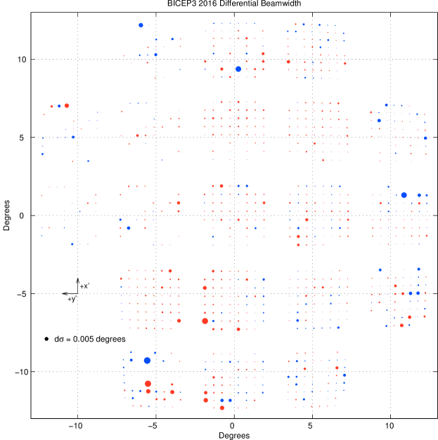
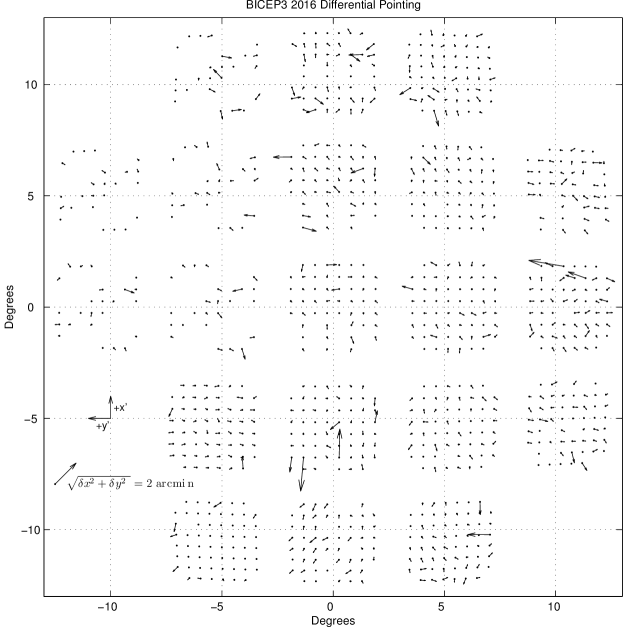
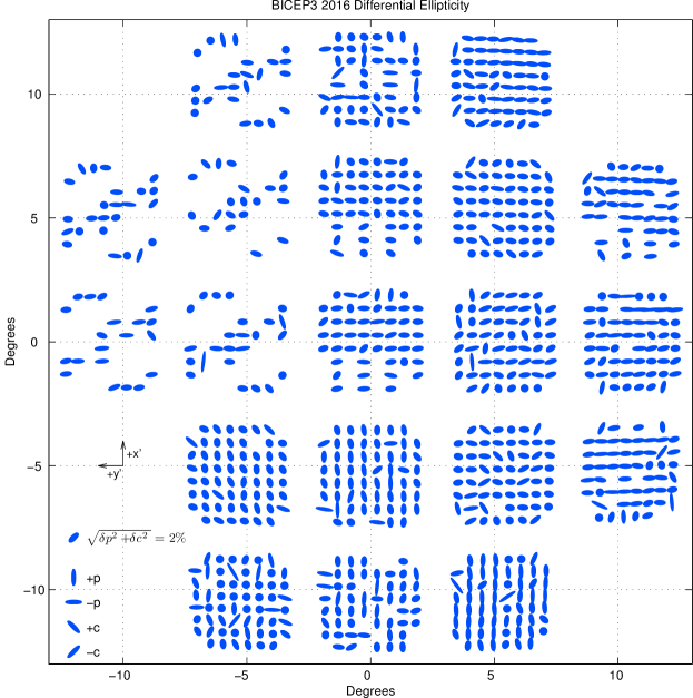
Figure 4 shows the differential beamwidth across the focal plane. The distribution is centered around zero, incoherent across the array, and small compared to the beamwidth – the median absolute differential beamwidth is compared to . Figure 5 shows the differential pointing, which for Bicep2 and Keck Array has traditionally been the largest beam shape mismatch mode. The distribution appears random across the focal plane, although several tiles exhibit coherence across the tile (e.g. Tiles 1 and 17); the median offset magnitude is 0.103 arcminutes. Figure 6 shows the differential ellipticity across the focal plane. We notice that differential ellipticity is largely coherent within tiles, and is mostly corresponding to ellipse orientations along the or axis. Tiles 8, 12, 13, 17, and 18 (those corresponding to MCE0; see Figure 3) are rotated with respect to the rest of the tiles. When their parameters are rotated so that all tiles have the same polarization orientation (i.e. with along the axis), we find that differential ellipticity is primarily , corresponding to the direction on the focal plane and the polarization axis on the tiles. The median differential ellipticity for the array in the same orientation is and .
5 COMPOSITE BEAM MAPS AND ARRAY-AVERAGED MAPS
5.1 Composite Maps
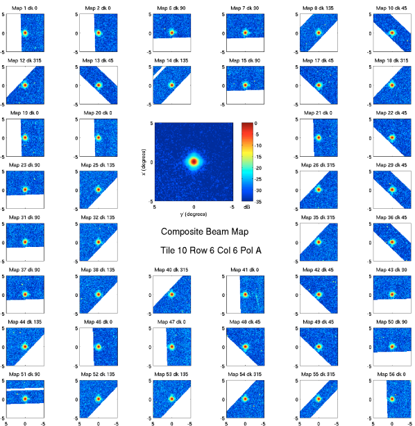
Since each detector has many beam maps at multiple boresight rotation angles, we can coadd them to obtain a high signal-to-noise composite map which covers all parts of the beam. We only use beam maps which have acceptable 2D Gaussian fits and in which both the and detectors were measured. Each component map is rotated to account for the boresight angle and centered on the common centroid for each detector pair. The ground is masked out since it causes visible response even in the demodulated maps. The composite map is then made from the median amplitude of each pixel across component maps. Figure 7 shows an example composite and the components which were used to make it. Spurious pixels in the component maps do not contribute to the final composite, which has visibly lower noise. In the 2016 dataset, only 38 optically responsive detectors have fewer than 10 good component maps (the typical detector has ). Although the composite beams shown in these proceedings only extend to away from the main beam, we can generate maps out to much larger angles. Future work with extended composite maps will allow for explicit measurement of extended beam response, including detailed constraints on reflections and total integrated sidelobe power out to large angles.
5.2 Array-Averaged Beam
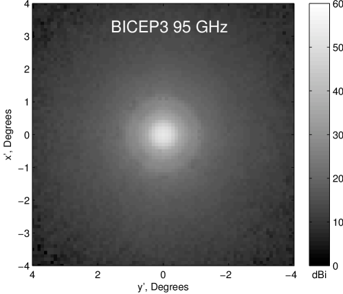
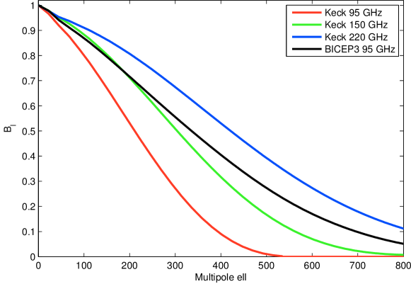
From the composite beam maps, we integral normalize and coadd all operational beams to form an array-averaged beam map. Figure 8 shows the averaged map in dBi (i.e. relative to an isotropic radiator); Airy ring structure is clearly visible. This map is then averaged in radial bins and Fourier transformed to obtain the circularly symmetric beam window function . The measured is corrected for the effect of the finite size of the source aperture:
| (3) |
where is the Bessel function of the first kind and is the diameter of the thermal source as seen from Bicep3. Figure 9 shows for Bicep3 and Keck Array, which we use to smooth the Planck input maps sampled in our timestream-level simulations.
6 DEPROJECTION AND EXPECTED SYSTEMATICS CONTROL
| Parameter | Keck Array 2015 (95 GHz) | Bicep2 (150 GHz) | Keck Array 2012 (150 GHz) |
|---|---|---|---|
| (degrees) | 0.306 | 0.220 | 0.216 |
| Detector count | 544 | 500 | 2480 |
| (arcmin) | 0.19 0.51 0.05 | 0.81 0.29 0.14 | 0.00 0.97 0.07 |
| (arcmin) | -0.24 0.48 0.04 | 0.78 0.35 0.14 | -0.21 0.54 0.06 |
| (degrees) | 0.000 0.001 0.001 | 0.000 0.001 0.001 | 0.000 0.001 0.001 |
| (+) | -0.010 0.008 0.002 | -0.002 0.013 0.011 | -0.007 0.015 0.003 |
| () | 0.002 0.003 0.002 | -0.003 0.012 0.005 | -0.007 0.009 0.003 |
| Parameter | Keck Array 2013 (150 GHz) | Bicep3 (95 GHz) | Keck Array 2015 (220 GHz) |
|---|---|---|---|
| (degrees) | 0.216 | 0.167 | 0.142 |
| Detector count | 2480 | 2400 | 992 |
| (arcmin) | 0.11 0.58 0.07 | 0.03 0.13 0.05 | -0.05 0.19 0.04 |
| (arcmin) | -0.22 0.56 0.06 | -0.12 0.17 0.05 | -0.01 0.28 0.04 |
| (degrees) | 0.000 0.001 0.001 | -0.001 0.001 0.001 | 0.000 0.001 0.001 |
| (+) | -0.011 0.012 0.002 | -0.006 0.017 0.004 | -0.017 0.008 0.006 |
| () | -0.004 0.007 0.002 | 0.000 0.005 0.004 | 0.003 0.007 0.006 |
In this section, we compare Bicep3’s differential beam parameters with those from Bicep2 and Keck Array (Table 2) and comment on the expected level of temperature-to-polarization leakage. In our CMB analysis pipeline, for each detector pair we perform a deprojection procedure in which the timestream data are regressed against templates of the real CMB temperature sky and its derivatives corresponding to the difference modes of two mismatched beams. The template multiplied by the best-fit regression coefficient is removed from the timestream, eliminating all leakage caused by a particular mode without external knowledge of the beams. As an alternative to deprojection, we may also choose to fix the coefficient which scales the deprojection template to the beam-map-derived value – we refer to this procedure as “subtraction.” Since differential gain is likely time-variable, we deproject it. Gain is not measured in beam maps because of the different TES used and loading environment between calibration measurements and CMB observations. In our previous results, we have chosen to deproject differential pointing; the measured correlation between beam-map-derived values and deprojection coefficients offers a robust check that our beam maps correspond to reality. Differential beamwidth has been found to be negligible, and so has neither been deprojected nor subtracted. We subtract differential ellipticity, because the real-sky correlation would be filtered out of our and spectra.
We first consider differential pointing, which for Bicep2 and Keck Array has been the beam mismatch mode contributing the most leakage and is independent of beam size. While Bicep2’s and were quite large, significant development effort[15] resulted in subsequent Keck Array focal planes at 95, 150, and 220 GHz with differential pointing that was several times smaller. Bicep3 is most similar to Keck Array 220 GHz in both the magnitude and the measurement precision. We can expect Bicep3’s pre-deprojection leakage from differential pointing to be much less than that of Bicep2; the distribution is also incoherent across the focal plane and will likely average down significantly.
Bicep3’s differential beamwidth is incoherent across the focal plane, centered close to zero, and is measured with precision similar to that of previous receivers. The level of leakage scales with one power of the beamwidth. Though in previous results we have found differential beamwidth to contribute negligible leakage, if beam map simulations show that this mode is significant for Bicep3, deprojection is a possibility.
Differential ellipticity is subtracted in our standard results, and therefore the precision requirements become stronger. We first observe that the measurement uncertainties in Table 2 are lower than those achieved by Bicep2, so we may expect that Bicep3 will be able to subtract leakage from differential ellipticity with higher precision than in previous results. We also note that the pre-subtraction leakage scales as the square of the beam size – Bicep3’s beams are the size of Bicep2’s, so a similar level of inherent differential ellipticity would produce significantly less leakage in Bicep3.
Ultimately, the effectiveness of deprojection is simulated explicitly using beam map simulations in which we convolve the Planck CMB temperature sky with the individual beam maps and process simulated timestreams just like the real data. We can then deproject these maps which contain only temperature-to-polarization leakage from measured beam mismatch. Based on comparison of the magnitude of the dominant differential pointing in Table 2, we expect the inherent leakage from beam mismatch modes to be equal to or lower than that from Bicep2.
Though deprojection removes all power corresponding to the coupling of the CMB temperature sky to a second-order expansion of the measured differential beam shape, real beams contain higher-order power which deprojection does not remove. Since the undeprojected beam mismatch residuals are often complicated, vary significantly across the focal plane, and may nontrivially cancel or amplify in the final map, the degree to which they will affect the final -mode power spectrum is not immediately obvious. The undeprojected residual level is the final result of the beam map simulations after deprojection. In the Bicep2 final results, we found that after deprojection of relative gain and differential pointing, and subtraction of differential ellipticity, we were able to constrain the residual temperature-to-polarization leakage to an equivalent . Similar simulations for Bicep3 will be run using the composite beam maps presented above, and we expect the measurement uncertainty on the beam maps to be much lower than that of Bicep2 because of higher signal strength afforded by the new thermal chopper.
7 CONCLUSIONS
In these proceedings we have presented a preliminary analysis of Bicep3’s far field beam performance for the 2016 observing season. Measurements were made during the 2015-2016 deployment season using a new chopped thermal microwave source with a 24” aperture. We find that Bicep3 has a median beamwidth of (23.6 arcminutes) and present the array-averaged profile. When detector pairs are fit to 2D elliptical Gaussians, we find that differential pointing, beamwidth, and ellipticity are similar to or lower than those measured for Bicep2 and Keck Array. The high-fidelity per-detector composite beam maps we have constructed from 77 beam mapping schedules will allow for explicit simulation of the undeprojected residual temperature-to-polarization leakage expected in the final polarization maps produced by Bicep3.
Acknowledgements.
The Bicep3 project has been made possible through support from the National Science Foundation (grant Nos. 1313158, 1313010, 1313062, 1313287, 1056465, and 0960243), the SLAC Laboratory Directed Research and Development Fund, the Canada Foundation for Innovation, and the British Columbia Development Fund. The development of antenna-coupled detector technology was supported by the JPL Research and Technology Development Fund and grants 06-ARPA206-0040 and 10-SAT10-0017 from the NASA ARPA and SAT programs. The development and testing of focal planes were supported by the Gordon and Betty Moore Foundation at Caltech. The computations in these proceedings were run on the Odyssey cluster supported by the FAS Science Division Research Computing Group at Harvard University. Tireless administrative support was provided by Irene Coyle, Kathy Deniston, Donna Hernandez, and Dana Volponi. We are grateful to Samuel Harrison and Hans Boenish as our 2015 and 2016 winterovers, respectively. We thank the staff of the US Antarctic Program and in particular the South Pole Station without whose help this research would not have been possible. We thank our Bicep1, Bicep2, Keck Array and Spider colleagues for useful discussions and shared expertise.References
- [1] Planck Collaboration, Ade, P. A. R., Aghanim, N., Arnaud, M., Arroja, F., Ashdown, M., Aumont, J., Baccigalupi, C., Ballardini, M., Banday, A. J., and et al., “Planck 2015 results. XX. Constraints on inflation,” ArXiv e-prints (Feb. 2015).
- [2] Polnarev, A. G., “Polarization and Anisotropy Induced in the Microwave Background by Cosmological Gravitational Waves,” Sov. Ast. 29, 607–613 (Dec. 1985).
- [3] BICEP2 Collaboration, Ade, P. A. R., Aikin, R. W., Barkats, D., Benton, S. J., Bischoff, C. A., Bock, J. J., Brevik, J. A., Buder, I., Bullock, E., Dowell, C. D., Duband, L., Filippini, J. P., Fliescher, S., Golwala, S. R., Halpern, M., Hasselfield, M., Hildebrandt, S. R., Hilton, G. C., Hristov, V. V., Irwin, K. D., Karkare, K. S., Kaufman, J. P., Keating, B. G., Kernasovskiy, S. A., Kovac, J. M., Kuo, C. L., Leitch, E. M., Lueker, M., Mason, P., Netterfield, C. B., Nguyen, H. T., O’Brient, R., Ogburn, R. W., Orlando, A., Pryke, C., Reintsema, C. D., Richter, S., Schwarz, R., Sheehy, C. D., Staniszewski, Z. K., Sudiwala, R. V., Teply, G. P., Tolan, J. E., Turner, A. D., Vieregg, A. G., Wong, C. L., Yoon, K. W., and Bicep2 Collaboration, “Detection of B-Mode Polarization at Degree Angular Scales by BICEP2,” Physical Review Letters 112, 241101 (June 2014).
- [4] BICEP2 and Keck Array Collaborations, Ade, P. A. R., Ahmed, Z., Aikin, R. W., Alexander, K. D., Barkats, D., Benton, S. J., Bischoff, C. A., Bock, J. J., Brevik, J. A., Buder, I., Bullock, E., Buza, V., Connors, J., Crill, B. P., Dowell, C. D., Dvorkin, C., Duband, L., Filippini, J. P., Fliescher, S., Golwala, S. R., Halpern, M., Harrison, S., Hasselfield, M., Hildebrandt, S. R., Hilton, G. C., Hristov, V. V., Hui, H., Irwin, K. D., Karkare, K. S., Kaufman, J. P., Keating, B. G., Kefeli, S., Kernasovskiy, S. A., Kovac, J. M., Kuo, C. L., Leitch, E. M., Lueker, M., Mason, P., Megerian, K. G., Netterfield, C. B., Nguyen, H. T., O’Brient, R., Ogburn, IV, R. W., Orlando, A., Pryke, C., Reintsema, C. D., Richter, S., Schwarz, R., Sheehy, C. D., Staniszewski, Z. K., Sudiwala, R. V., Teply, G. P., Thompson, K. L., Tolan, J. E., Turner, A. D., Vieregg, A. G., Weber, A. C., Willmert, J., Wong, C. L., and Yoon, K. W., “BICEP2/Keck Array V: Measurements of B-mode Polarization at Degree Angular Scales and 150 GHz by the Keck Array,” Astrophys. J. 811, 126 (Oct. 2015).
- [5] BICEP2/Keck and Planck Collaborations, Ade, P. A. R., Aghanim, N., Ahmed, Z., Aikin, R. W., Alexander, K. D., Arnaud, M., Aumont, J., Baccigalupi, C., Banday, A. J., Barkats, D., Barreiro, R. B., Bartlett, J. G., Bartolo, N., Battaner, E., Benabed, K., Benoît, A., Benoit-Lévy, A., Benton, S. J., Bernard, J.-P., Bersanelli, M., Bielewicz, P., Bischoff, C. A., Bock, J. J., Bonaldi, A., Bonavera, L., Bond, J. R., Borrill, J., Bouchet, F. R., Boulanger, F., Brevik, J. A., Bucher, M., Buder, I., Bullock, E., Burigana, C., Butler, R. C., Buza, V., Calabrese, E., Cardoso, J.-F., Catalano, A., Challinor, A., Chary, R.-R., Chiang, H. C., Christensen, P. R., Colombo, L. P. L., Combet, C., Connors, J., Couchot, F., Coulais, A., Crill, B. P., Curto, A., Cuttaia, F., Danese, L., Davies, R. D., Davis, R. J., de Bernardis, P., de Rosa, A., de Zotti, G., Delabrouille, J., Delouis, J.-M., Désert, F.-X., Dickinson, C., Diego, J. M., Dole, H., Donzelli, S., Doré, O., Douspis, M., Dowell, C. D., Duband, L., Ducout, A., Dunkley, J., Dupac, X., Dvorkin, C., Efstathiou, G., Elsner, F., Enßlin, T. A., Eriksen, H. K., Falgarone, E., Filippini, J. P., Finelli, F., Fliescher, S., Forni, O., Frailis, M., Fraisse, A. A., Franceschi, E., Frejsel, A., Galeotta, S., Galli, S., Ganga, K., Ghosh, T., Giard, M., Gjerløw, E., Golwala, S. R., González-Nuevo, J., Górski, K. M., Gratton, S., Gregorio, A., Gruppuso, A., Gudmundsson, J. E., Halpern, M., Hansen, F. K., Hanson, D., Harrison, D. L., Hasselfield, M., Helou, G., Henrot-Versillé, S., Herranz, D., Hildebrandt, S. R., Hilton, G. C., Hivon, E., Hobson, M., Holmes, W. A., Hovest, W., Hristov, V. V., Huffenberger, K. M., Hui, H., Hurier, G., Irwin, K. D., Jaffe, A. H., Jaffe, T. R., Jewell, J., Jones, W. C., Juvela, M., Karakci, A., Karkare, K. S., Kaufman, J. P., Keating, B. G., Kefeli, S., Keihänen, E., Kernasovskiy, S. A., Keskitalo, R., Kisner, T. S., Kneissl, R., Knoche, J., Knox, L., Kovac, J. M., Krachmalnicoff, N., Kunz, M., Kuo, C. L., Kurki-Suonio, H., Lagache, G., Lähteenmäki, A., Lamarre, J.-M., Lasenby, A., Lattanzi, M., Lawrence, C. R., Leitch, E. M., Leonardi, R., Levrier, F., Lewis, A., Liguori, M., Lilje, P. B., Linden-Vørnle, M., López-Caniego, M., Lubin, P. M., Lueker, M., Macías-Pérez, J. F., Maffei, B., Maino, D., Mandolesi, N., Mangilli, A., Maris, M., Martin, P. G., Martínez-González, E., Masi, S., Mason, P., Matarrese, S., Megerian, K. G., Meinhold, P. R., Melchiorri, A., Mendes, L., Mennella, A., Migliaccio, M., Mitra, S., Miville-Deschênes, M.-A., Moneti, A., Montier, L., Morgante, G., Mortlock, D., Moss, A., Munshi, D., Murphy, J. A., Naselsky, P., Nati, F., Natoli, P., Netterfield, C. B., Nguyen, H. T., Nørgaard-Nielsen, H. U., Noviello, F., Novikov, D., Novikov, I., O’Brient, R., Ogburn, R. W., Orlando, A., Pagano, L., Pajot, F., Paladini, R., Paoletti, D., Partridge, B., Pasian, F., Patanchon, G., Pearson, T. J., Perdereau, O., Perotto, L., Pettorino, V., Piacentini, F., Piat, M., Pietrobon, D., Plaszczynski, S., Pointecouteau, E., Polenta, G., Ponthieu, N., Pratt, G. W., Prunet, S., Pryke, C., Puget, J.-L., Rachen, J. P., Reach, W. T., Rebolo, R., Reinecke, M., Remazeilles, M., Renault, C., Renzi, A., Richter, S., Ristorcelli, I., Rocha, G., Rossetti, M., Roudier, G., Rowan-Robinson, M., Rubiño Martín, J. A., Rusholme, B., Sandri, M., Santos, D., Savelainen, M., Savini, G., Schwarz, R., Scott, D., Seiffert, M. D., Sheehy, C. D., Spencer, L. D., Staniszewski, Z. K., Stolyarov, V., Sudiwala, R., Sunyaev, R., Sutton, D., Suur-Uski, A.-S., Sygnet, J.-F., Tauber, J. A., Teply, G. P., Terenzi, L., Thompson, K. L., Toffolatti, L., Tolan, J. E., Tomasi, M., Tristram, M., Tucci, M., Turner, A. D., Valenziano, L., Valiviita, J., Van Tent, B., Vibert, L., Vielva, P., Vieregg, A. G., Villa, F., Wade, L. A., Wandelt, B. D., Watson, R., Weber, A. C., Wehus, I. K., White, M., White, S. D. M., Willmert, J., Wong, C. L., Yoon, K. W., Yvon, D., Zacchei, A., and Zonca, A., “Joint Analysis of BICEP2/Keck Array and Planck Data,” Phys. Rev. Lett. 114, 101301 (Mar 2015).
- [6] BICEP2 Collaboration, Keck Array Collaboration, Ade, P. A. R., Ahmed, Z., Aikin, R. W., Alexander, K. D., Barkats, D., Benton, S. J., Bischoff, C. A., Bock, J. J., Bowens-Rubin, R., Brevik, J. A., Buder, I., Bullock, E., Buza, V., Connors, J., Crill, B. P., Duband, L., Dvorkin, C., Filippini, J. P., Fliescher, S., Grayson, J., Halpern, M., Harrison, S., Hilton, G. C., Hui, H., Irwin, K. D., Karkare, K. S., Karpel, E., Kaufman, J. P., Keating, B. G., Kefeli, S., Kernasovskiy, S. A., Kovac, J. M., Kuo, C. L., Leitch, E. M., Lueker, M., Megerian, K. G., Netterfield, C. B., Nguyen, H. T., O’Brient, R., Ogburn, R. W., Orlando, A., Pryke, C., Richter, S., Schwarz, R., Sheehy, C. D., Staniszewski, Z. K., Steinbach, B., Sudiwala, R. V., Teply, G. P., Thompson, K. L., Tolan, J. E., Tucker, C., Turner, A. D., Vieregg, A. G., Weber, A. C., Wiebe, D. V., Willmert, J., Wong, C. L., Wu, W. L. K., and Yoon, K. W., “Improved Constraints on Cosmology and Foregrounds from BICEP2 and Keck Array Cosmic Microwave Background Data with Inclusion of 95 GHz Band,” Physical Review Letters 116, 031302 (Jan. 2016).
- [7] Wu, W. L. K., Ade, P. A. R., Ahmed, Z., Alexander, K. D., Amiri, M., Barkats, D., Benton, S. J., Bischoff, C. A., Bock, J. J., Bowens-Rubin, R., Buder, I., Bullock, E., Buza, V., Connors, J. A., Filippini, J. P., Fliescher, S., Grayson, J. A., Halpern, M., Harrison, S. A., Hilton, G. C., Hristov, V. V., Hui, H., Irwin, K. D., Kang, J., Karkare, K. S., Karpel, E., Kefeli, S., Kernasovskiy, S. A., Kovac, J. M., Kuo, C. L., Megerian, K. G., Netterfield, C. B., Nguyen, H. T., O’Brient, R., Ogburn, R. W., Pryke, C., Reintsema, C. D., Richter, S., Sorensen, C., Staniszewski, Z. K., Steinbach, B., Sudiwala, R. V., Teply, G. P., Thompson, K. L., Tolan, J. E., Tucker, C. E., Turner, A. D., Vieregg, A. G., Weber, A. C., Wiebe, D. V., Willmert, J., and Yoon, K. W., “Initial Performance of Bicep3: A Degree Angular Scale 95 GHz Band Polarimeter,” Journal of Low Temperature Physics 184, 765–771 (Aug. 2016).
- [8] BICEP2 Collaboration, Ade, P. A. R., Aikin, R. W., Amiri, M., Barkats, D., Benton, S. J., Bischoff, C. A., Bock, J. J., Brevik, J. A., Buder, I., Bullock, E., Davis, G., Day, P. K., Dowell, C. D., Duband, L., Filippini, J. P., Fliescher, S., Golwala, S. R., Halpern, M., Hasselfield, M., Hildebrandt, S. R., Hilton, G. C., Irwin, K. D., Karkare, K. S., Kaufman, J. P., Keating, B. G., Kernasovskiy, S. A., Kovac, J. M., Kuo, C. L., Leitch, E. M., Llombart, N., Lueker, M., Netterfield, C. B., Nguyen, H. T., O’Brient, R., Ogburn, IV, R. W., Orlando, A., Pryke, C., Reintsema, C. D., Richter, S., Schwarz, R., Sheehy, C. D., Staniszewski, Z. K., Story, K. T., Sudiwala, R. V., Teply, G. P., Tolan, J. E., Turner, A. D., Vieregg, A. G., Wilson, P., Wong, C. L., and Yoon, K. W., “BICEP2. II. Experiment and three-year Data Set,” Astrophys. J. 792, 62 (Sept. 2014).
- [9] BICEP2 and Keck Array Collaborations, Ade, P. A. R., Aikin, R. W., Barkats, D., Benton, S. J., Bischoff, C. A., Bock, J. J., Bradford, K. J., Brevik, J. A., Buder, I., Bullock, E., Dowell, C. D., Duband, L., Filippini, J. P., Fliescher, S., Golwala, S. R., Halpern, M., Hasselfield, M., Hildebrandt, S. R., Hilton, G. C., Hui, H., Irwin, K. D., Kang, J. H., Karkare, K. S., Kaufman, J. P., Keating, B. G., Kefeli, S., Kernasovskiy, S. A., Kovac, J. M., Kuo, C. L., Leitch, E. M., Lueker, M., Megerian, K. G., Netterfield, C. B., Nguyen, H. T., O’Brient, R., Ogburn, IV, R. W., Orlando, A., Pryke, C., Richter, S., Schwarz, R., Sheehy, C. D., Staniszewski, Z. K., Sudiwala, R. V., Teply, G. P., Thompson, K., Tolan, J. E., Turner, A. D., Vieregg, A. G., Weber, A. C., Wong, C. L., and Yoon, K. W., “BICEP2/Keck Array. IV. Optical Characterization and Performance of the BICEP2 and Keck Array Experiments,” Astrophys. J. 806, 206 (June 2015).
- [10] BICEP2 Collaboration, Ade, P. A. R., Aikin, R. W., Barkats, D., Benton, S. J., Bischoff, C. A., Bock, J. J., Brevik, J. A., Buder, I., Bullock, E., Dowell, C. D., Duband, L., Filippini, J. P., Fliescher, S., Golwala, S. R., Halpern, M., Hasselfield, M., Hildebrandt, S. R., Hilton, G. C., Irwin, K. D., Karkare, K. S., Kaufman, J. P., Keating, B. G., Kernasovskiy, S. A., Kovac, J. M., Kuo, C. L., Leitch, E. M., Lueker, M., Netterfield, C. B., Nguyen, H. T., O’Brient, R., Ogburn, IV, R. W., Orlando, A., Pryke, C., Richter, S., Schwarz, R., Sheehy, C. D., Staniszewski, Z. K., Sudiwala, R. V., Teply, G. P., Tolan, J. E., Turner, A. D., Vieregg, A. G., Wong, C. L., and Yoon, K. W., “BICEP2 III: Instrumental Systematics,” Astrophys. J. 814, 110 (Dec. 2015).
- [11] Grayson, J. A. et al., “BICEP3 performance overview and plans for a multi-receiver array,” in [These proceedings ], Society of Photo-Optical Instrumentation Engineers (SPIE) Conference Series 9914 (2016).
- [12] Hui, H. et al., “Second year detector performance of BICEP3,” in [These proceedings ], Society of Photo-Optical Instrumentation Engineers (SPIE) Conference Series 9914 (2016).
- [13] Bullock, E. et al., “Dielectric Sheet Calibrator for measuring polarization angles of Keck Array telescope,” in [These proceedings ], Society of Photo-Optical Instrumentation Engineers (SPIE) Conference Series 9914 (2016).
- [14] Ahmed, Z., Amiri, M., Benton, S. J., Bock, J. J., Bowens-Rubin, R., Buder, I., Bullock, E., Connors, J., Filippini, J. P., Grayson, J. A., Halpern, M., Hilton, G. C., Hristov, V. V., Hui, H., Irwin, K. D., Kang, J., Karkare, K. S., Karpel, E., Kovac, J. M., Kuo, C. L., Netterfield, C. B., Nguyen, H. T., O’Brient, R., Ogburn, R. W., Pryke, C., Reintsema, C. D., Richter, S., Thompson, K. L., Turner, A. D., Vieregg, A. G., Wu, W. L. K., and Yoon, K. W., “BICEP3: a 95GHz refracting telescope for degree-scale CMB polarization,” in [Society of Photo-Optical Instrumentation Engineers (SPIE) Conference Series ], Society of Photo-Optical Instrumentation Engineers (SPIE) Conference Series 9153 (Aug. 2014).
- [15] O’Brient, R., Ade, P. A. R., Ahmed, Z., Aikin, R. W., Amiri, M., Benton, S., Bischoff, C., Bock, J. J., Bonetti, J. A., Brevik, J. A., Burger, B., Davis, G., Day, P., Dowell, C. D., Duband, L., Filippini, J. P., Fliescher, S., Golwala, S. R., Grayson, J., Halpern, M., Hasselfield, M., Hilton, G., Hristov, V. V., Hui, H., Irwin, K., Kernasovskiy, S., Kovac, J. M., Kuo, C. L., Leitch, E., Lueker, M., Megerian, K., Moncelsi, L., Netterfield, C. B., Nguyen, H. T., Ogburn, R. W., Pryke, C. L., Reintsema, C., Ruhl, J. E., Runyan, M. C., Schwarz, R., Sheehy, C. D., Staniszewski, Z., Sudiwala, R., Teply, G., Tolan, J. E., Turner, A. D., Tucker, R. S., Vieregg, A., Wiebe, D. V., Wilson, P., Wong, C. L., Wu, W. L. K., and Yoon, K. W., “Antenna-coupled TES bolometers for the Keck array, Spider, and Polar-1,” in [Society of Photo-Optical Instrumentation Engineers (SPIE) Conference Series ], Society of Photo-Optical Instrumentation Engineers (SPIE) Conference Series 8452 (Sept. 2012).