Thickness Engineered Tunnel Field-Effect Transistors based on Phosphorene
Abstract
Thickness engineered tunneling field-effect transistors (TE-TFET) as a high performance ultra-scaled steep transistor is proposed. This device exploits a specific property of 2D materials: layer thickness dependent energy bandgap (Eg). Unlike the conventional hetero-junction TFETs, TE-TFET uses spatially varying layer thickness to form a hetero-junction. This offers advantages by avoiding the interface states and lattice mismatch problems. Furthermore, it boosts the ON-current to 1280 for 15nm channel length. TE-TFET shows a channel length scalability down to 9nm with constant field scaling . Providing a higher ON current, phosphorene TE-TFET outperforms the homojunction phosphorene TFET and the TMD TFET in terms of extrinsic energy-delay product. In this work, the operation principles of TE-TFET and its performance sensitivity to the design parameters are investigated by the means of full-band atomistic quantum transport simulation.
I Introduction
Since first experimental realization of Appenzeller et al. (2004) in tunnel field-effect transistors (TFETs), these devices have been the main candidate for reduction of supply voltage and energy consumption in electronic devices. TFETs lower the energy consumption of a transistor by removing the hot carrier injection from the source region of the transistor. However, TFETs have 2 main challenges: 1) small ON-current and 2) channel length scaling.
The small ON-current challenge of TFET is even more pronounced in the conventional CMOS channel materials, namely Si and Ge. These materials have an indirect gap which requires phonon assistance for band-to-band tunneling (BTBT). Si has also a large Eg which further reduces . Smaller band gap channel materials such as Ge can improve the tunneling current and , however they also increase the , hence degrade the ratioToh et al. (2008). Previously, several designs have been proposed to increase the ON-current of TFETs such as 1) heterostructure channels Avci and Young (2013); Shih and Chien (2011), 2) dielectric engineering Ilatikhameneh et al. (2015a, 2016) 3) internal polarization Li et al. (2015), and 4) 2D materials Ilatikhameneh et al. (2015b); Chen et al. (2016); Ilatikhameneh et al. (2015c).

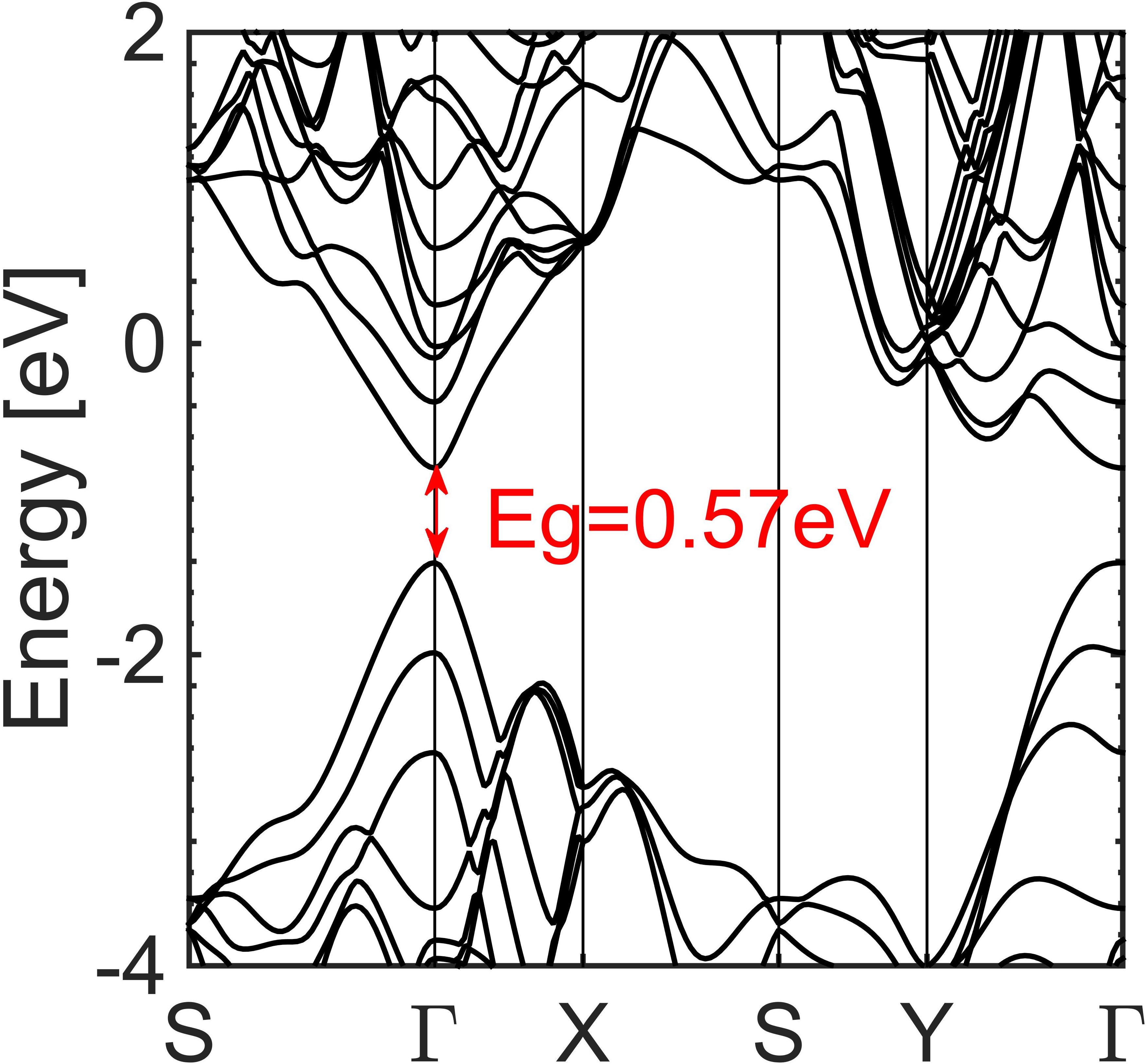
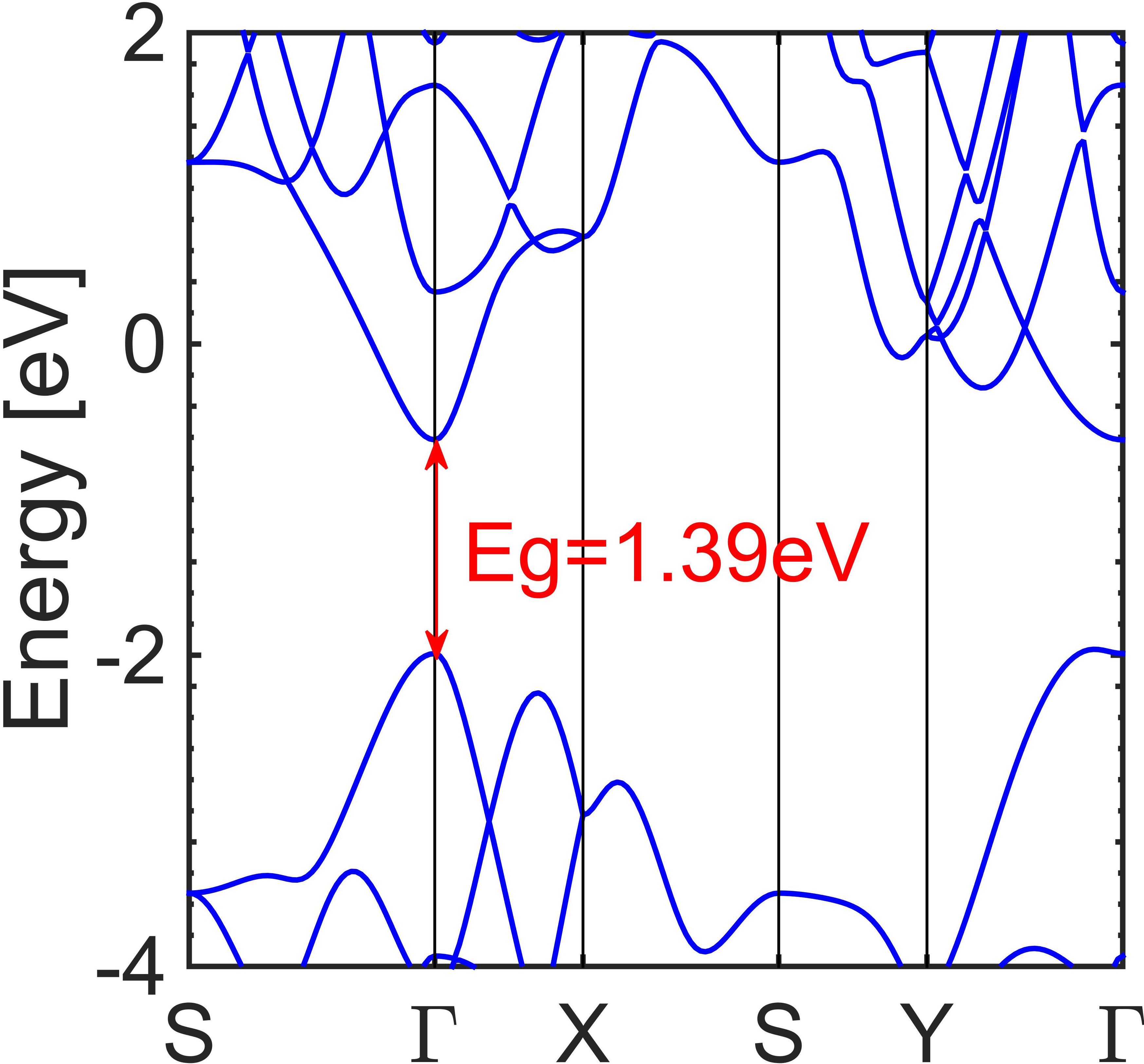
Heterostructure channels improve the performance of TFETs by using small Eg as source, Si as channel material to improve while keeping small. Unfortunately, the large lattice mismatch People and Bean (1985); Vandooren et al. (2013) and interface states Kim et al. (2015); Ilatikhameneh, Klimeck, and Rahman (2016a); Koswatta, Koester, and Haensch (2010) between the materials prevent the formation of an ideal heterojunction. Artifical heterojunctions based on a single channel material have been achieved in graphene by varying the width of graphene nanoribbon (GNR)Lam et al. (2010). However, the edge roughness and device-to-device variations due to the lack of atomic level control in top down fabrication pose a big challenge for their technology developmentLuisier and Klimeck (2009); Yoon and Guo (2007); Basu et al. (2008).
Novel 2D materials have interesting properties which can be used to provide artificial heterostructures. The bandgap of transition metal dichacogenides (TMDs), graphene and phosphorene depends on the layer thickness Chu et al. (2015); Kang, Zhang, and Wei (2016); Cai, Zhang, and Zhang (2014); Chen et al. ; Chen et al. (2015a). In these materials, artificial heterojunctions can be achieved by spatially varying the layer thicknessHowell et al. (2015). Unlike the GNR heterojunctions where a sub-nanometer width control is required, a spatially varying layer thickness can be easily achieved with 2D material exfoliation and transfer techniques Mas-Balleste et al. (2011); Coleman et al. (2011) . Therefore, a thickness engineered TFET (TE-TFET) which exploits this spatially varying layer thickness technique is proposed in this letter. TE-TFET is designed to have a small Eg in source and the channel near source and larger Eg in the rest of device. TE-TFET can be applied to any material that has a band gap dependence on layer thickness. In this work, phosphorene is chosen as the channel material due to the fact that multi-layer phosphorene is direct gap material Tran et al. (2014); Liu et al. (2014) and its bandgap range includes the optimum bandgap of 1.2 for TFET applications Ilatikhameneh, Klimeck, and Rahman (2016b); Ameen et al. (2015); Liu et al. (2015). Although, the bandgap of TMD flakes depends on the flake thickness, only monolayer TMDs are direct gap materials.
A TE-TFET has several advantages: (1) Artificial heterojunction structure avoids the problems with lattice mismatch and interface states observed in a conventional heterojunction; (2) the ON-state current can be enhanced due to the small bandgap and small tunnel distance in source-channel interface; (3) the OFF-state current remains small because of the large Eg barrier inside the channel.
The device structure of the TE-TFET based on phosphorene is shown in Fig. 1a. The layer thickness and the length of the small band gap region inside the channel region are denoted by and . The dependence of device performance on these design parameters and total channel length will be discussed in details in section III. Finally, the capacitance voltage (CV) characteristics and energy delay product comparison with homojunction phosphorene TFET are discussed.
II Simulation Details
| Layer | 1 | 2 | 3 | 4 |
|---|---|---|---|---|
| Eg(eV) | 1.390 | 0.803 | 0.570 | 0.481 |
| 4.56 | 7.41 | 8.77 | 9.98 | |
| 1.36 | 1.52 | 1.80 | 2.04 |
The Hamiltonian of phosphorene is represented using a 10 band second nearest neighbor tight binding model. The tight-binding parameters are well calibrated to match the band structure and effective mass from density function theory (DFT) HSE06 by the standard mapping method Tan et al. (2015, 2013). Fig. 1b and Fig. 1c show the tight-binding bandstructure of 3L- and 1L-phosphorene, respectively. The Eg of phosphorene flakes with different number of layers are listed in Table 1. The relative permittivity for both in-plane and out-of-plane are taken from Wang, Kawazoe, and Geng (2015) and are also listed in Table 1. All the transport characteristics of the TE-TFET have been simulated using the self-consistent Poisson-Non Equilibrium Green′s Function (NEGF) method in the multi-scale Chen et al. (2015b) and multi-physics Miao et al. (2016); Chen et al. (2015c) Nano-Electronic MOdeling (NEMO5) tool Fonseca et al. (2013).
The default parameters of the TE-TFET device (, and shown in Fig. 1a) are set to , and 3L respectively. is 0.4V for 12nm. Source and drain regions are doped with the doping level of . Equivalent oxide thickness (EOT) is set to 0.5nm. Constant field scaling E is chosen for the device scaling, where .
III Results and Discussion
The transfer characteristics () of TE-TFET compared against 1L, 2L, and 3L phosphorene TFETs is shown in Fig. 2. All the curves, except the 3L-TFET, are shifted to have the same of . The minimum current of 3L-TFET is , which is larger than the required level. Hence, 3L phosphorene TFET is shifted by the same voltage shift as that of the TE-TFET.
Fig. 2 shows that TE-TFET has the advantages of both 3L and 1L homojunction TFETs: small of 1L-TFET and high ON-current of 3L-TFET. The of about is achieved in TE-TFET with , which is 2 times larger than 2L-TFET. , the current when SS becomes Seabaugh and Lu (2014), in TE-TFET is about which is larger by two orders compared to that of the best phosphorene TFET.


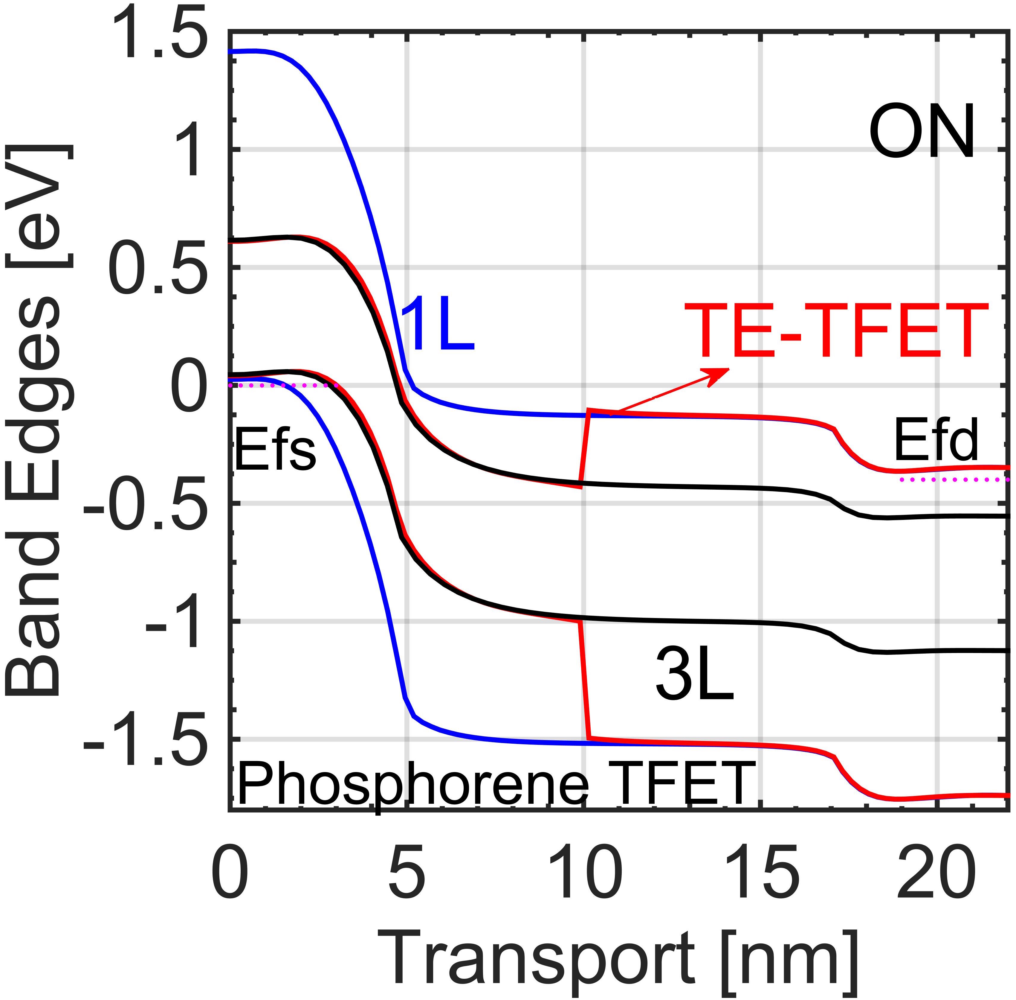
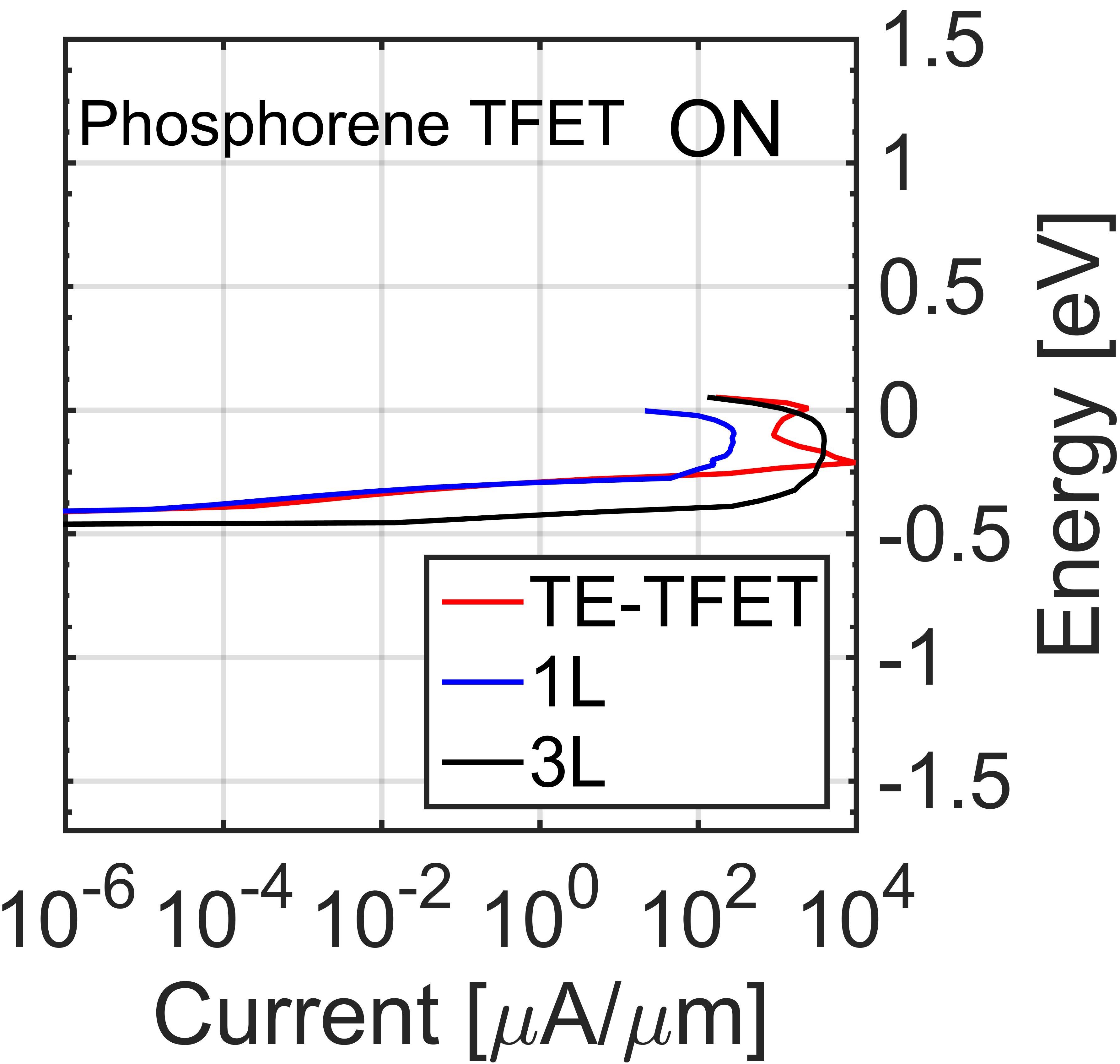
A comparison of TE-TFET against 3L-TFET in the ON-state and 1L-TFET in the OFF-state are shown in Fig. 3; the band diagrams along with energy resolved current of these devices are also plotted. At OFF state, as shown in Fig. 3a and b, TE-TFET has a larger barrier compared to the 3L-TFET which blocks the direct source-to-drain tunneling in the 1L section. TE-TFET thus achieves a small OFF-current. In the ON-state, shown in Fig. 3c and d, TE-TFET has a smaller tunnel distance compared to the 1L-TFET. Thus, TE-TFET is able to achieve a higher ON-current compared to 1L-TFET due to the smaller tunnel distance at the source-channel interface. TE-TFET has over four decades of drain current. In spite of high current levels in TE-TFET, its ON-current does not reach that of 3L-TFET due to the 1L barrier inside channel that blocks the current as shown in Fig. 3c and d.
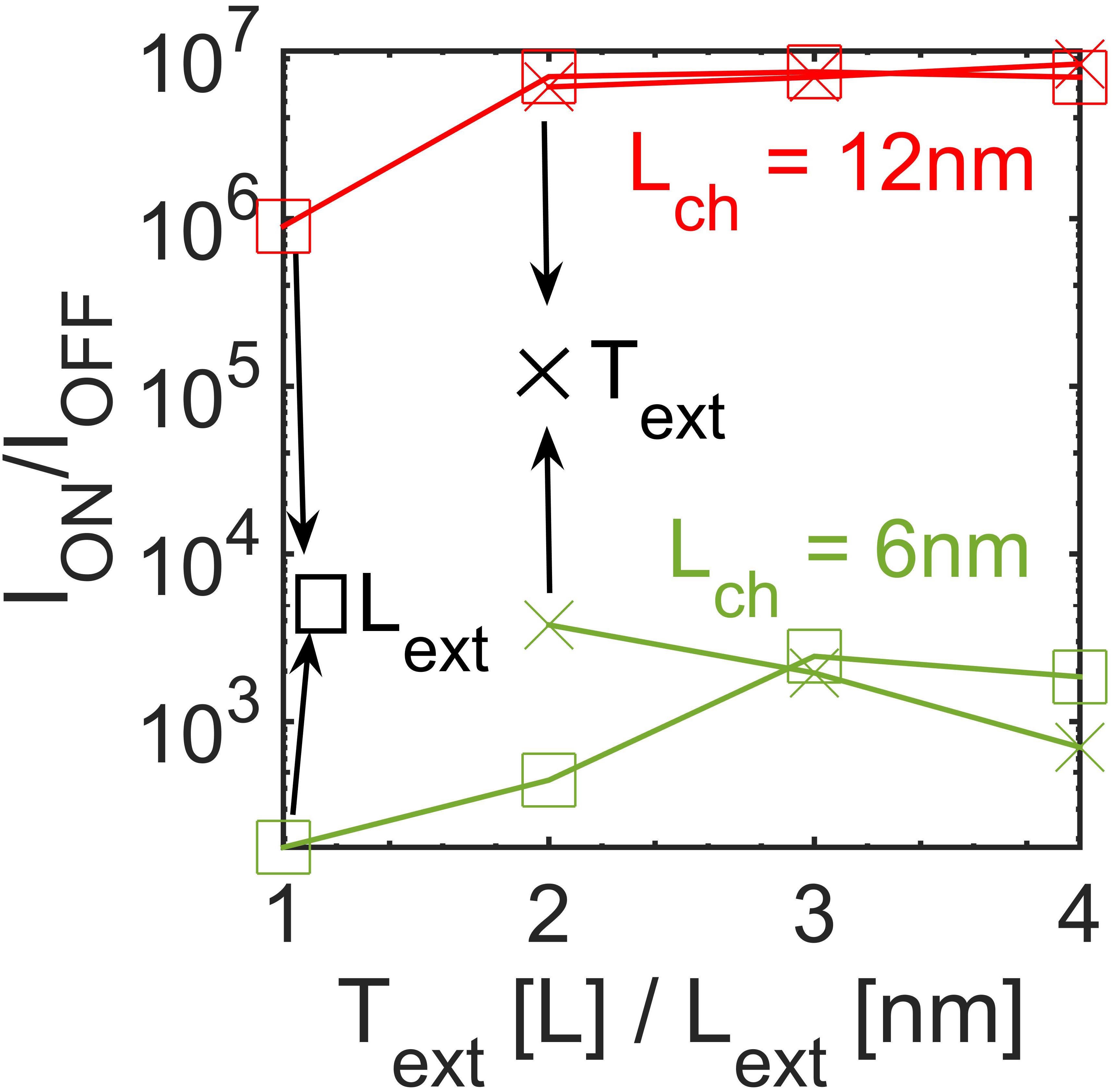
The impact of device design parameters and on its performance is discussed for a TE-TFET with . As shown in Fig. 4a, 4L, 3L and 2L flakes are used in the extension region of TE-TFET which translate into a bandgap of 0.481eV, 0.570eV and 0.803eV respectively. The ON-current can be improved from to by replacing 3L with 4L in the extension region. TE-TFET with 2L extension still achieves an ON-current similar to 3L, but its degrades by two orders of magnitude. Fig. 4b shows the impact of on the performance of TE-TFET; by increasing from 1nm to 2nm, the ON current improves by an order of magnitude. However, the performance saturates for beyond 2nm (up to 4nm). This minimum value of is because for the cases where is too short, the tunneling in the ON-state does not occur completely in the small Eg region. Hence, a lower ON-current is achieved with below 2nm.
The ratio as a function of and for and is plotted in Fig. 4c. For the 6nm channel length with of 0.2V (constant field scaling), the trend is similar to that of . The OFF current of TE-TFET with increases beyond due to the fact that 1L barrier inside the channel is not long enough to block the leakage current. For a fair comparison, is fixed to for analysis, whereas is set to for study. It is worthwhile to mention that there is only a small range of for in which the SS is smaller than .

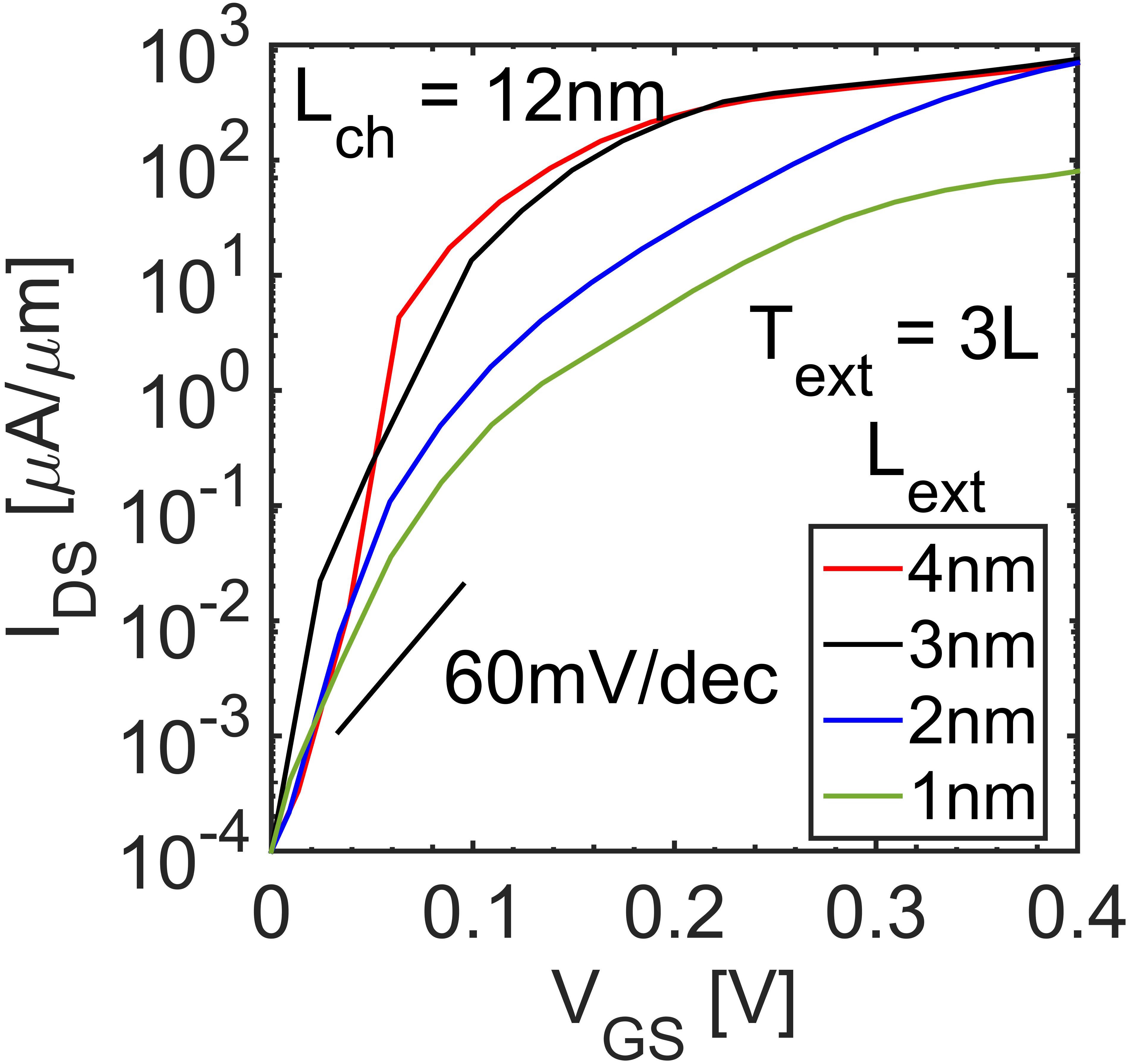
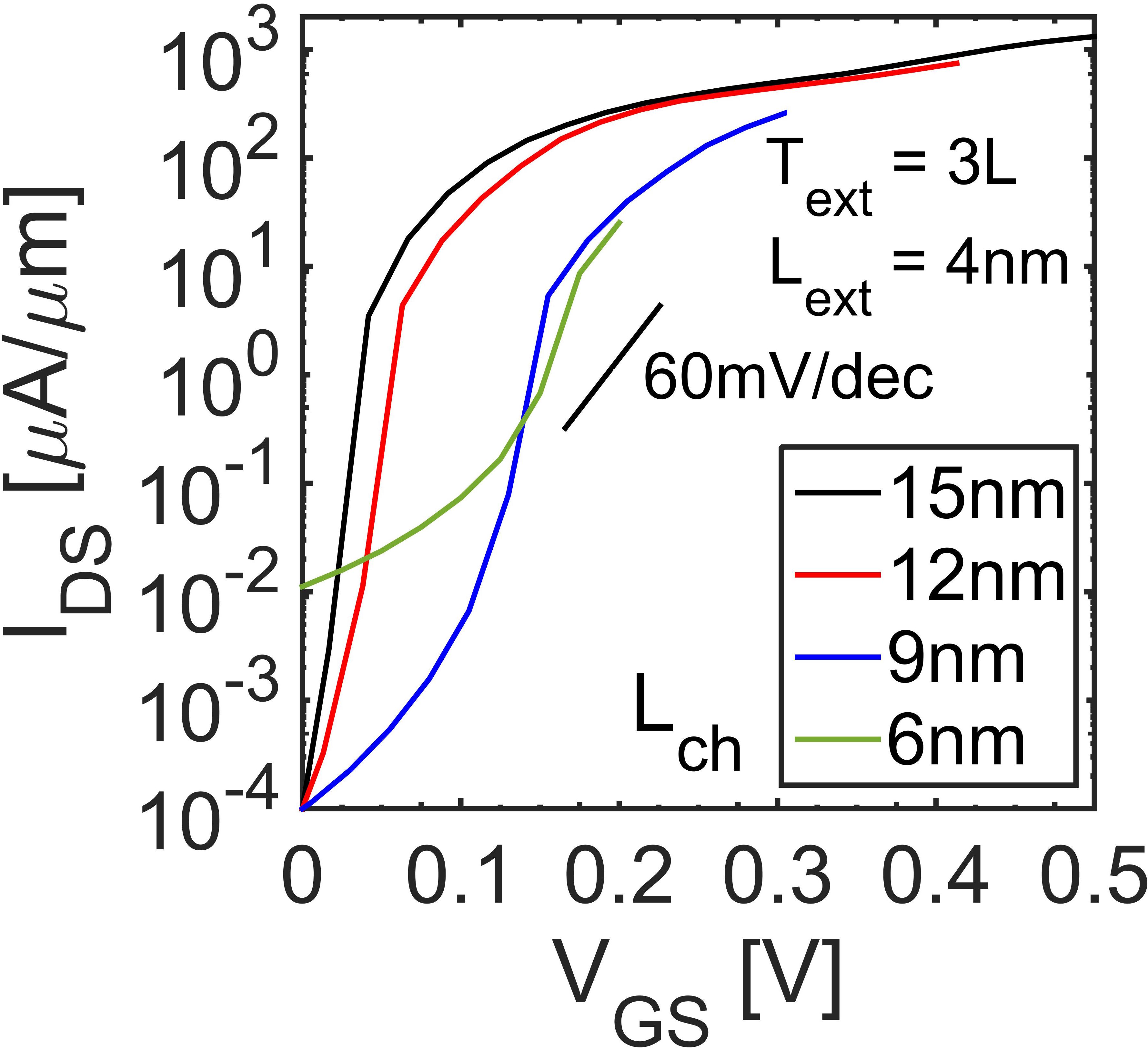
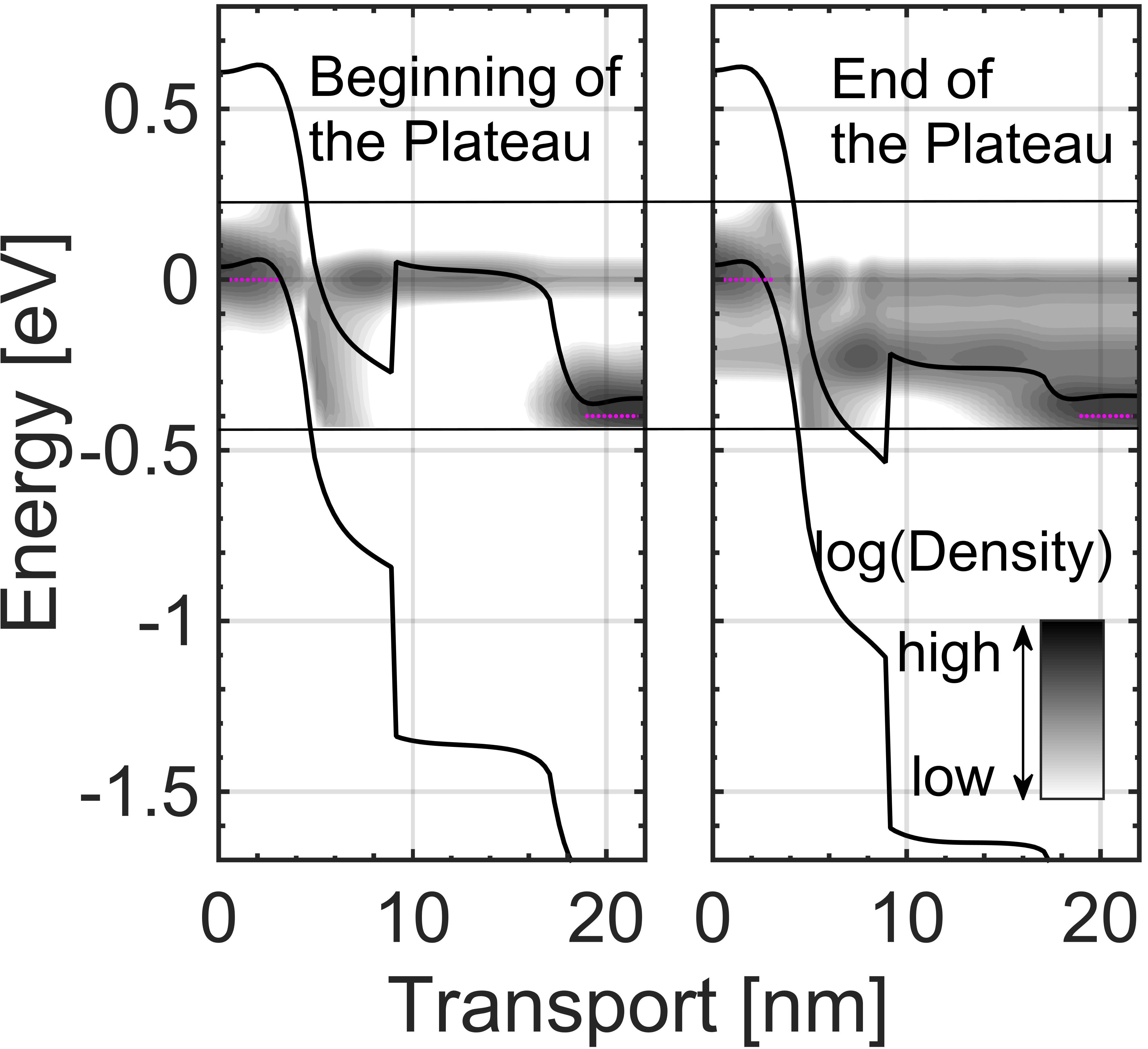
Constant field scaling E of TE-TFETs is studied in this part (). Fig. 4d shows that the of TE-TFET is over 6 orders of magnitude for above 9nm, however there is a noticeable increase in for the channel length of 6nm. Fig. 5a shows the impact of scaling on the total gate capacitance characteristics (). The gate capacitance is noticeably smaller than most TMD materials. This smaller capacitance originates from the smaller effective mass of phosphorene Ameen et al. (2015). Unlike homojunctions, the CV curve of TE-TFET has a plateau region. This plateau in CV appears due to the strong density of states (DOS) modulation within the quantum well region. Fig. 5b illustrates the carrier density along the transport direction at the beginning and the end of the plateau region. In both cases, source Fermi level is aligned with the maximum DOS. From the beginning to the end, is aligned with a lower DOS due to the confinement. This decrease in DOS in the quantum well region compensates for the increase in DOS inside the 1L region and forms the plateau in the C-V curves. The length of the plateau region is different for different since the carrier density is also influenced by the carrier injection from drain Ilatikhameneh, Klimeck, and Rahman (2015).

Compared to homojunction phosphorenene TFETs Ameen et al. (2015), TE-TFETs exhibit higher ON-currents and slightly higher capacitances. These higher ON-currents translate to an improvement in 32 bit adder energy-delay product as shown in Fig. 6. The 32-bit adder energy-delay product is calculated using BCB 3.0 model Nikonov and Young (2015) in which the parasitic capacitances are taken into account. The circuit parameters required in BCB model are taken from ITRS roadmap.

IV Conclusion
In conclusion, thickness engineered tunneling field-effect transistor (TE-TFET)is proposed and evaluated in this work. By taking advantage of flake-thickness-dependent direct bandgap in phosphorene, an artificial heterostructure TFET can be achieved. The absence of interface, between different materials in artificial heterojunctions, allows TE-TFET to avoid the interface states and lattice mismatch problems observed in conventional heterojunction TFETs while providing similar boost in the ON-current of 1280 with a 15nm channel length. TE-TFETs are scalable down to 9nm with constant field scaling E . Offering higher ON-current, TE-TFETs outperform the best homojunction phosphorene TFETs and TMD TFETs in terms of circuit energy-delay product.
Acknowledgements.
This work was supported in part by the Center for Low Energy Systems Technology, one of six centers of STARnet, and in part by the Semiconductor Research Corporation Program through Microelectronics Advanced Research Corporation and Defense Advanced Research Projects Agency.References
- Appenzeller et al. (2004) J. Appenzeller, Y.-M. Lin, J. Knoch, and P. Avouris, “Band-to-band tunneling in carbon nanotube field-effect transistors,” Physical Review Letters 93, 196805 (2004).
- Toh et al. (2008) E.-H. Toh, G. H. Wang, G. Samudra, and Y.-C. Yeo, “Device physics and design of germanium tunneling field-effect transistor with source and drain engineering for low power and high performance applications,” Journal of Applied Physics 103, 104504 (2008).
- Avci and Young (2013) U. E. Avci and I. A. Young, “Heterojunction tfet scaling and resonant-tfet for steep subthreshold slope at sub-9nm gate-length,” in 2013 IEEE International Electron Devices Meeting (IEEE, 2013) pp. 4–3.
- Shih and Chien (2011) C.-H. Shih and N. D. Chien, “Sub-10-nm tunnel field-effect transistor with graded si/ge heterojunction,” IEEE Electron Device Letters 32, 1498–1500 (2011).
- Ilatikhameneh et al. (2015a) H. Ilatikhameneh, T. Ameen, G. Klimeck, J. Appenzeller, and R. Rahman, “Dielectric engineered tunnel field-effect transistor,” Electron Device Letters, IEEE 36, 1097–1100 (2015a).
- Ilatikhameneh et al. (2016) H. Ilatikhameneh, G. Klimeck, J. Appenzeller, and R. Rahman, “Design rules for high performance tunnel transistors from 2d materials,” (2016).
- Li et al. (2015) W. Li, S. Sharmin, H. Ilatikhameneh, R. Rahman, Y. Lu, J. Wang, X. Yan, A. Seabaugh, G. Klimeck, D. Jena, et al., “Polarization-engineered iii-nitride heterojunction tunnel field-effect transistors,” IEEE Journal on Exploratory Solid-State Computational Devices and Circuits 1, 28–34 (2015).
- Ilatikhameneh et al. (2015b) H. Ilatikhameneh, Y. Tan, B. Novakovic, G. Klimeck, R. Rahman, and J. Appenzeller, “Tunnel field-effect transistors in 2-d transition metal dichalcogenide materials,” IEEE Journal on Exploratory Solid-State Computational Devices and Circuits 1, 12–18 (2015b).
- Chen et al. (2016) F. W. Chen, H. Ilatikhameneh, G. Klimeck, Z. Chen, and R. Rahman, “Configurable electrostatically doped high performance bilayer graphene tunnel fet,” IEEE Journal of the Electron Devices Society 4, 124–128 (2016).
- Ilatikhameneh et al. (2015c) H. Ilatikhameneh, F. W. Chen, R. Rahman, and G. Klimeck, “Electrically doped 2d material tunnel transistor,” in Computational Electronics (IWCE), 2015 International Workshop on (2015) pp. 1–3.
- People and Bean (1985) R. People and J. C. Bean, “Calculation of critical layer thickness versus lattice mismatch for gexsi1−x/si strained‐layer heterostructures,” Applied Physics Letters 47, 322–324 (1985).
- Vandooren et al. (2013) A. Vandooren, D. Leonelli, R. Rooyackers, A. Hikavyy, K. Devriendt, M. Demand, R. Loo, G. Groeseneken, and C. Huyghebaert, “Analysis of trap-assisted tunneling in vertical si homo-junction and sige hetero-junction tunnel-fets,” Solid-State Electronics 83, 50–55 (2013).
- Kim et al. (2015) M. Kim, Y. K. Wakabayashi, M. Yokoyama, R. Nakane, M. Takenaka, and S. Takagi, “Ge/si heterojunction tunnel field-effect transistors and their post metallization annealing effect,” Electron Devices, IEEE Transactions on 62, 9–15 (2015).
- Ilatikhameneh, Klimeck, and Rahman (2016a) H. Ilatikhameneh, G. Klimeck, and R. Rahman, “Can homojunction tunnel fets scale below 10 nm?” IEEE Electron Device Letters 37, 115–118 (2016a).
- Koswatta, Koester, and Haensch (2010) S. O. Koswatta, S. J. Koester, and W. Haensch, “On the possibility of obtaining mosfet-like performance and sub-60-mv/dec swing in 1-d broken-gap tunnel transistors,” IEEE Transactions on Electron Devices 57, 3222–3230 (2010).
- Lam et al. (2010) K.-T. Lam, D. Seah, S.-K. Chin, S. B. Kumar, G. Samudra, Y.-C. Yeo, and G. Liang, “A simulation study of graphene-nanoribbon tunneling fet with heterojunction channel,” Electron Device Letters, IEEE 31, 555–557 (2010).
- Luisier and Klimeck (2009) M. Luisier and G. Klimeck, “Performance analysis of statistical samples of graphene nanoribbon tunneling transistors with line edge roughness,” Applied Physics Letters 94, 223505 (2009).
- Yoon and Guo (2007) Y. Yoon and J. Guo, “Effect of edge roughness in graphene nanoribbon transistors,” Applied Physics Letters 91, 073103 (2007).
- Basu et al. (2008) D. Basu, M. Gilbert, L. Register, S. K. Banerjee, and A. H. MacDonald, “Effect of edge roughness on electronic transport in graphene nanoribbon channel metal-oxide-semiconductor field-effect transistors,” Applied Physics Letters 92, 042114 (2008).
- Chu et al. (2015) T. Chu, H. Ilatikhameneh, G. Klimeck, R. Rahman, and Z. Chen, “Electrically tunable bandgaps in bilayer mos2,” Nano Letters 15, 8000–8007 (2015), pMID: 26560813, http://dx.doi.org/10.1021/acs.nanolett.5b03218 .
- Kang, Zhang, and Wei (2016) J. Kang, L. Zhang, and S.-H. Wei, “A unified understanding of the thickness-dependent bandgap transition in hexagonal two-dimensional semiconductors,” The Journal of Physical Chemistry Letters 7, 597–602 (2016), pMID: 26800573, http://dx.doi.org/10.1021/acs.jpclett.5b02687 .
- Cai, Zhang, and Zhang (2014) Y. Cai, G. Zhang, and Y.-W. Zhang, “Layer-dependent band alignment and work function of few-layer phosphorene,” Scientific reports 4 (2014).
- (23) F. W. Chen, H. Ilatikhameneh, G. Klimeck, R. Rahman, T. Chu, and Z. Chen, “Achieving a higher performance in bilayer graphene fet-strain engineering,” in 2015 International Conference on Simulation of Semiconductor Processes and Devices (SISPAD), (IEEE) pp. 177–181.
- Chen et al. (2015a) F. Chen, H. Ilatikhameneh, T. Chu, R. Rahman, J. Appenzeller, Z. Chen, and G. Klimeck, “Transport properties of bilayer graphene field effect transistor,” in Proc. TECHCON (2015).
- Howell et al. (2015) S. L. Howell, D. Jariwala, C.-C. Wu, K.-S. Chen, V. K. Sangwan, J. Kang, T. J. Marks, M. C. Hersam, and L. J. Lauhon, “Investigation of band-offsets at monolayer–multilayer mos2 junctions by scanning photocurrent microscopy,” Nano letters 15, 2278–2284 (2015).
- Mas-Balleste et al. (2011) R. Mas-Balleste, C. Gomez-Navarro, J. Gomez-Herrero, and F. Zamora, “2d materials: to graphene and beyond,” Nanoscale 3, 20–30 (2011).
- Coleman et al. (2011) J. N. Coleman, M. Lotya, A. O’Neill, S. D. Bergin, P. J. King, U. Khan, K. Young, A. Gaucher, S. De, R. J. Smith, et al., “Two-dimensional nanosheets produced by liquid exfoliation of layered materials,” Science 331, 568–571 (2011).
- Tran et al. (2014) V. Tran, R. Soklaski, Y. Liang, and L. Yang, “Layer-controlled band gap and anisotropic excitons in few-layer black phosphorus,” Physical Review B 89, 235319 (2014).
- Liu et al. (2014) F. Liu, Y. Wang, X. Liu, J. Wang, and H. Guo, “Ballistic transport in monolayer black phosphorus transistors,” IEEE Transactions on Electron Devices 61, 3871–3876 (2014).
- Ilatikhameneh, Klimeck, and Rahman (2016b) H. Ilatikhameneh, G. Klimeck, and R. Rahman, “Can homojunction tunnel fets scale below 10 nm?” IEEE Electron Device Letters 37, 115–118 (2016b).
- Ameen et al. (2015) T. A. Ameen, H. Ilatikhameneh, G. Klimeck, and R. Rahman, “Few-layer phosphorene: An ideal 2d material for tunnel transistors,” arXiv preprint arXiv:1512.05021 (2015).
- Liu et al. (2015) F. Liu, Q. Shi, J. Wang, and H. Guo, “Device performance simulations of multilayer black phosphorus tunneling transistors,” Applied Physics Letters 107, 203501 (2015).
- Tan et al. (2015) Y. P. Tan, M. Povolotskyi, T. Kubis, T. B. Boykin, and G. Klimeck, “Tight-binding analysis of si and gaas ultrathin bodies with subatomic wave-function resolution,” Physical Review B 92, 085301 (2015).
- Tan et al. (2013) Y. Tan, M. Povolotskyi, T. Kubis, Y. He, Z. Jiang, G. Klimeck, and T. B. Boykin, “Empirical tight binding parameters for gaas and mgo with explicit basis through dft mapping,” Journal of Computational Electronics 12, 56–60 (2013).
- Wang, Kawazoe, and Geng (2015) V. Wang, Y. Kawazoe, and W. Geng, “Native point defects in few-layer phosphorene,” Physical Review B 91, 045433 (2015).
- Chen et al. (2015b) F. W. Chen, M. Manfra, G. Klimeck, and T. Kubis, “Nemo5: Why must we treat topological insulator nanowires atomically?” in International Workshop on Computational Electronics (IWCE 2015) (http://in4.iue.tuwien.ac.at/pdfs/iwce/iwce18_2015/IWCE_2015_33-34.pdf, 2015).
- Miao et al. (2016) K. Miao, S. Sadasivam, J. Charles, G. Klimeck, T. Fisher, and T. Kubis, “Büttiker probes for dissipative phonon quantum transport in semiconductor nanostructures,” Applied Physics Letters 108, 113107 (2016).
- Chen et al. (2015c) F. Chen, L. Jauregui, Y. Tan, M. Manfra, Y. Chen, K. Gerhard, and T. Kubis, “In-surface confinement of topological insulator nanowire surface states,” Applied Physics Letters 107, 121605 (2015c).
- Fonseca et al. (2013) J. E. Fonseca, T. Kubis, M. Povolotskyi, B. Novakovic, A. Ajoy, G. Hegde, H. Ilatikhameneh, Z. Jiang, P. Sengupta, and Y. Tan, “Efficient and realistic device modeling from atomic detail to the nanoscale,” Journal of Computational Electronics 12, 592–600 (2013).
- Seabaugh and Lu (2014) A. Seabaugh and H. Lu, “Tunnel field-effect transistors - update,” in Solid-State and Integrated Circuit Technology (ICSICT), 2014 12th IEEE International Conference on (2014) pp. 1–4.
- Ilatikhameneh, Klimeck, and Rahman (2015) H. Ilatikhameneh, G. Klimeck, and R. Rahman, “2d tunnel transistors for ultra-low power applications: Promises and challenges,” in Energy Efficient Electronic Systems (E3S), 2015 Fourth Berkeley Symposium on (2015) pp. 1–3.
- Nikonov and Young (2015) D. Nikonov and I. Young, “Benchmarking of beyond-cmos exploratory devices for logic integrated circuits,” IEEE Exploratory Solid-State Computational Devices and Circuits 1, 3–11 (2015).