A Method to Produce Intense Positron Beams via Electro Pair Production on Electrons
Abstract
Intense positron beams can be prepared via electro production with the reaction due to the availability of high current electron beams. Head on collisions inside of a magnetic field of a solenoid are used to produce unpolarized/polarized positrons via - pair production. A flux of unpolarized positrons, , has been obtained as a result of calculations for a special case of parameters with beam currents for both electron beams of =10 mA and beam momenta of =0.63 MeV/c and =10.0 MeV/c. Intensities are an order of magnitude smaller in the case of polarized positrons due to a reduced current of one of the electron beams. Suitable cuts on momenta of the positrons allow to achieve a polarization transfer from electrons to positrons of 85% reducing, however, the intensity to 27%.
Physikalisches Institut, Universität Bonn, Nussallee 12, D-53115 Bonn, Germany
1 Introduction
Positrons and beams of positrons find applications in several branches of science. Positrons as a probe are used in solid state physics as well as in particle physics, covering an energy range from eV up to 250 GeV, respectively. The status of the field at low and medium energies and the need for improved positron beams have been stressed in several recent publications [1],[2],[3]. Ideally, the beam qualities should approach that of electron beams and in certain cases, polarized beams are needed, too. So far, the decay of radio isotopes via -decay and electron-positron pair production via photo production in the electric field of heavy nuclei have been the reactions of choice. Positrons leaving beam pipes on nuclear power reactors provide, so far, the most intense beams of thermalized positrons, however, in the process of thermalization only a small fraction, of the order of , survive from around /s to /s down to /s to /s. Pair production on the other hand allows preparation of beams of positrons over a wide range of energy. The accelerator facility in Saclay, France [4], serves as an early example. Beams of positrons have been prepared in the 1980ties in Saclay, with a 720 MeV electron LINAC, for particle physics experiments in the several hundred MeV region. Currents of 20-50 nA for a beam with a momentum spread of p/p=1.5% and an emittance of 4 mmmrad have been prepared via bremsstrahlung processes on high Z targets. An efficiency of 0.1 has been reached to transform an incoming electron beam into a positron beam. A similar set-up was used with the Mainz LINAC [5] for positron annihilation experiments. Both facilities were able to run with electron beam currents of the order of . Problems to overcome were the construction of high Z targets standing the heat and build a shielding against a high flux of neutrons around those targets.

2 Electro production within a magnetic field of a solenoid
With the development of injectors providing polarized electron beams, pair production offers a convenient way to produce polarized positrons via the use of circular polarized -rays. Improvements and a better exploitation of the method for future applications are necessary and possible. In this paper the reaction of trident (triplet) pair production is proposed as a source of a positron beam. Fig. 1 shows the total cross section for positron production via the reaction together with the total cross section of the reaction taken from Ref. [6]. The similar sizes of the cross sections demonstrate that the Coulomb field plays the decisive role for the reaction despite the large mass difference of the targets. The cross section for photo production of pairs on electrons =1 mb at =10 MeV (see Fig. 1) has to be compared with the cross section on high Z elements e.g. on Ta(Z=73) with =10 b. The difference explains the preferred use of high Z targets for photo production of positrons. By using electrons as a target special properties of the reaction and kinematic must be found and explored in order to compensate for the smallness of that cross section. Instead of photo production electro production might offer a way to achieve a high enough luminosity for being competitive with other methods. A schematic set-up for an electro production experiment is shown in Fig. 2. Two electron beams collide head on and produce electron-positron pairs in a longitudinal magnetic field within a solenoid.


2.1 Luminosity
Luminosity L for such a set-up for one interaction zone is given by:
| (1) |
and stand for the number of electrons/s in the beams, respectively, and and for the Gaussian beam profiles of the two intersecting beams of same extension. D.C. beams of electrons are assumed in the following discussion but other time structures are not excluded. Electron currents in the mA range with useful emittances became available in the last years e.g. by the development of energy recovering linacs. The results of those developments gave reason to consider a set-up as shown in Fig. 2 for a positron source with remarkable features. However, cross sections for electro production are generally two orders of magnitude smaller compared to photo production cross sections investigating the same reactions at the same energy transfers. Thus, the beam extensions and at interaction zone will be decisive whether a positron current of the order of 1010 positrons/s or more can be reached.
2.2 Particle trajectories in a field of a solenoid
Solenoid fields are used to focus charged particle beams in beam lines for many applications. The propagation of beams in beam lines with solenoids is well incorporated in beam transport programs. The trajectories of single particles, however, are of special importance for the application of extended solenoid fields providing several foci and, thus, new opportunities for colliding beams see e.g. [7]. The trajectory of a charged particle entering the solenoid field parallel to the symmetry axis, z-direction, with distance R to the symmetry axis is considered under the assumption of a fringe field with no extension (hard edge approximation) and incoming momentum large enough in order to leave the magnetic field with little change in its transverse coordinates. Inside, the particle’s trajectory forms a helix, see Fig. 3, propagating in z- direction with radius R/2 in the projected x-y plane whose center is at distance R/2 from the symmetry axis of the solenoid. The particle rotates with the cyclotron frequency = (rad/sT), with e and m the charge and rest mass of the particle, with E as total energy of the particle and B the magnetic field inside the solenoid. All particles rotate with the same frequency independently of R.
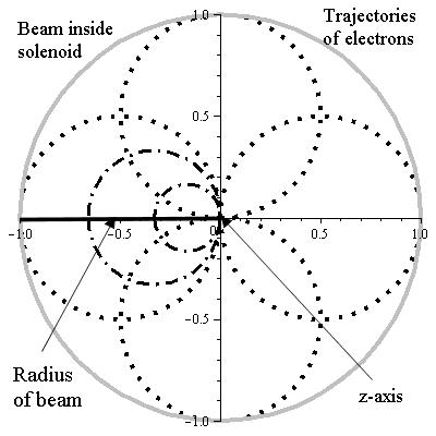
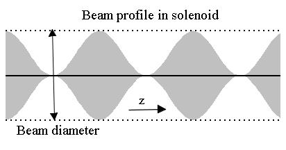
Fig. 4 illustrates the projection of the rotation of six particles onto the x-y plane in one period, demonstrating the focusing to the symmetry axis of the solenoid. That means that for an exactly parallel beam of particles with diameter 2R outside the field and a constant density along the z-axis a density modulated beam traverses the solenoid as shown in Fig. 5. for the outer four particles. The inner two particles reach at the same time the axis as the outer ones but have slightly different velocities in z-direction because the radii of the helices are different. A discussion of all relevant quantities for fixed beam parameters can be found in the appendix. The conservation of canonical angular momentum
| (2) |
serves as a starting point for discussion of trajectories of electrons, with as vector potential and as the momentum of electrons. L=0 stands for a beam outside of the magnetic field parallel to the symmetry axis. Due to induced Lenz force that value remains zero inside. Quantitatively, a solenoid magnet with field has a vector potential =, with being the angle of rotation in x-y plane. A current (due to Lenz law) is induced in such a way that r. A real beam has, however, transverse momenta due to finite emittances and, thus changing somewhat the ideal picture. One of the challenges for the preparation of a beam will be to optimize the parameters in view to achieve high luminosity. Another important relation carrying out calculations is given by the radius of an electron in a homogeneous magnetic field . With special choices of beam and field parameters a case study will be presented in order to prepare a discussion of the luminosity.
2.3 A case study
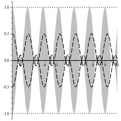
Two electron beams are brought to interaction in a set-up as shown schematically in Fig. 2. Electron beam e2 with momentum =10 MeV/c interacts in a longitudinal magnetic field with a field strength of 1.0 Tesla with electron beam e1 with momentum 0.63 MeV/c corresponding to a kinetic energy of 300 keV. In order to reach relevant numbers for luminosity detailed calculations of the trajectories of the beams in the solenoid have to be performed. The results are presented in the appendix. As so far discussed, all particle trajectories pass through the magnetic axis of the solenoid. However, the velocities in z-direction of particle trajectories change due to their r-dependence. The size of the effect finds its expression on the different path lengths s of the helices, e.g. for peripheral particles, with s=1.032 m and s=1.0001 m for the e1- and e2 beam, respectively. The number of foci are for the e1-beam 78 and 5 for the e2-beam. Remains to be discussed the waists of the beams finding its expression in the formula for the luminosity by located at the foci which are shown in Fig. 5 for a trajectory of electrons entering the magnetic field coming from the periphery of the beam. It stands for all electrons entering the magnetic field parallel to the axis of the field. However, such an ideal situation can only be approached by optimizing the available parameters, like the incoming momenta and the emittances of the particles involved, the strength of the magnetic field and the diameter of the beam. Unavoidable transverse components of the incoming beams lead to trajectories including or excluding the axis of field symmetry and, thus, widening the waists of beams. Non zero values of emittances lead to transverse momentum components of the beams. Focusing and defocusing of beams lead to transverse momentum components, too. Fig. 6 shows the beam profiles for particles situated on the periphery of the beam with r=1 mm and half way to the periphery with r= 0.5 mm. A inclusion of the axis of symmetry by a distance of has been assumed in order to amplify the effect of a transverse component of momentum responsible for waists of the beams. In the case study outlined in the appendix values for the two beams of and have been calculated for beam e1 and beam e2, respectively. However, as input for formula 1 defining the luminosity a value for as well as of will be taken and, thus, including possible uncertainties in calibrating the set-up. Experience from other set-ups give confidence that calibrations with a precision of the order can be achieved. Fig. 6 shows in addition that the velocities in z-direction are r-dependent, as mentioned above. However, that behavior of the beam particles has no relevance for the application considered in this paper. The number of foci is another important outcome of the calculations presented in the Appendix. Five foci of beam e2 and 78 foci of bam e1 demonstrate the usefulness of a solenoid to create many interaction regions for two beams in head on collisions.
2.4 Positron production with electrons
2.4.1 Thresholds
The threshold energy for the reaction with e1 at rest in the lab. system yields according to the equation for invariant masses
| (3) |
The threshold energy for a beam with a head on collision with beam with energy and momentum results to or Those energies should be compared with the c.m. energy for the chosen e2 and e1 energies.
2.4.2 Kinematic of positron momenta
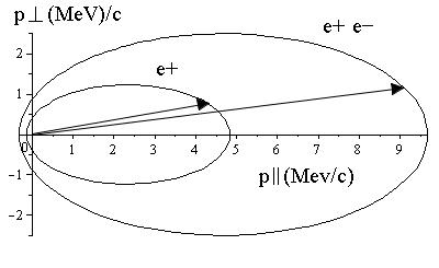
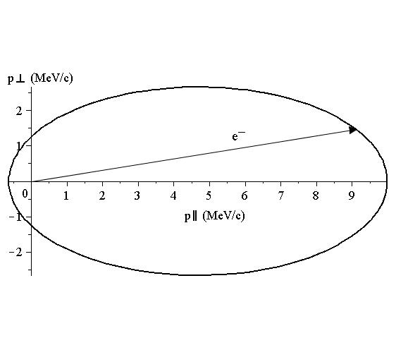
The reaction considered has two particles in the initial state and four particles in the final state all with the same mass. The available momentum space for positrons can be determined by reducing the four body state to a two body state considering the c.m. movements of two pairs of particles consisting of and . From those distributions it is possible to extract the available momentum space of the positrons. Fig. 7 shows that momentum space. The positrons are almost all emitted into forward direction with the highest momentum reaching almost =5 MeV/c. The transverse momentum with =1.25 MeV/c leads to a helical trajectory with a radius r of =4.2 mm.
2.4.3 Energy of beam e2 in the rest system of beam e1
The cross sections are usually measured in the laboratory system with e1 at rest.That is the case shown in Fig. 1 for - pair production cross sections. In head on collisions, however, smaller energies are needed to cover the same energy region in the c.m.-system. The lab. energy is given by a Lorentz transformation
| (4) |
yields =28.32 MeV. That means energy has to be transformed accordingly when using a cross section for reaction as shown in Fig. 2.
2.5 Intensity of the electron beams and luminosity
The knowledge of the number of electrons/s in the beams e1 and e2 provides the last ingredients for formula (1) in order to calculate the luminosity. Conservative numbers for electron currents with = =10 mA will do it at this point of discussion. In section 5 values already reached will be addressed. With all numbers in place the luminosity reads
| (5) |
That value for the luminosity L for one interaction zone has to be multiplied with the product of the periods of the beams e1 and e2 in the solenoid. With that product 78 the luminosity of formula (5) increases to
| (6) |
The last step towards a calculation of positron rates needs a knowledge of the cross section.
3 Cross sections and reaction rates
3.1 Positron production
A cross section for the reaction has been reported in reference [8]. The formula
| (7) |
has been extracted as a fit to the results of two previous publications [9] and [10]. The energy of beam e2, =10.01 MeV, corresponds to =28.32 MeV in the laboratory system. The total cross section for that energy yields, using formula 7, . Thus, the rate of the number of positrons results from the product luminosity times cross section:
| (8) |
A discussion of uncertainty of the value of could not be found. However, the value has the right order of magnitude as estimates along the lines of virtual photon theory suggest.
3.2 Other scattering processes
In addition to pair production two other reactions take place: Elastic electron scattering and bremsstrahlung. Elastic scattering is by far the largest contribution of all three processes. Fig. 8 shows the momenta of the scattered electrons. The Moeller cross section, however, has two poles from the t and the u channel as well contributing to the cross section. The differential cross section [11], [12]
| (9) |
show forward, interference and backward pieces, with as fine structure constant, Planck constant divided by , s, t, u Mandelstam variables and c.m. momentum of beam e2. The total cross section, that means the integration of formula (9), diverges. How to go around the singularities in principle, see [13]. An integration over the range of positron angles yields still a value of 0.5 b . The size of elastic cross section drops proportional to s, the positron production rate increases with the incoming electron energy. Thus elastic scattering will be one of several boundary conditions by selection of an optimal set-up. The bremsstrahl contribution plays a role, too, not so much as an additional electron background, but as a real photon beam into direction of the beam lines of the incoming beams.
4 Polarized positrons
An additional advantage using pair production via photo- or electro induced reactions, besides reaching high rates, resides in the possibility to create polarized positrons. Already very early [14] it has been realized that longitudinally polarized electrons emit bremsstrahlung with circular polarization. Olson and Maximon [15] extended that finding by showing that pair production induced with circularly polarized photons produce polarized positrons. Finally, based on the general method described e.g. in [18], first devised by Weizsaecker-Williams [16] and [17], tractable expressions could be found. Formulae for virtual photon spectra, see e.g. [19, 20], have been developed in order to understand and describe quantitatively electro induced reactions.The region close to the endpoint, that means highest energy point of the virtual photon spectrum, has been identified as energy region to carry out reliable calculations in order to extract photo production cross sections out of electro production data, see e.g. [21]. Thus, along those lines it can be understood and calculated that circularly polarized electrons produce polarized positrons. Given the fact that electron beams with polarization are routinely used at several laboratories that method can be applied without further difficulties. The degree of polarization transfer depends on the (virtual) photon energy transfer as shown in Fig. 9. The helicity transfer for (virtual) photons close to the end point of the spectrum comes close to 100.
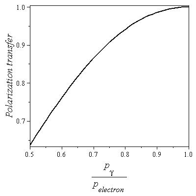
Thus, positrons with high momenta, see Fig. 7, have a high polarization close to the polarization of the incoming
electrons.
Calculations within the framework of virtual photon theory for the given case show that
the integrated intensity of the
virtual photon spectrum from threshold to the highest energy yield a polarization of positrons of 52 ,
integration of the upper half of the spectrum result in an intensity of 44 and a polarization of 76 and,
finally, integration of the
upper third of the virtual spectrum yield an intensity of 27 and a polarization of 85. Those values for the
polarization have to be multiplied with the degree of polarization of the electrons in order to get the final
polarization
of the positrons.
The low mass of the target might lead to corrections [20]. However,
the corrections, especially close to the end point region, are probably not so large in order to change the picture
described above. The closeness of the cross sections of real photons on the proton and the electron shown in Fig. 1
suggest, as already mentioned above, that the target mass plays not a dominant role in that reaction.
5 Developments towards higher electron currents
One of the useful properties of the method resides in a lesser dependence on the emittances of the beams in order to achieve high luminosities compared to intersecting beams e.g. using storage rings. All particles entering the magnetic field parallel to the symmetry axis touch the axis. However, particles entering at a larger distance R to the symmetry axis do have a smaller and , thus, a larger trajectory s, see Appendix. Thus, part of the transverse emittance gets transferred towards the longitudinal direction. That property helps to use higher beam currents with poor transverse emittance in order to increase luminosity. Remarkable progress has been achieved recently by preparing high electron beam current [22],[25]. Electron beam currents of up to =100 mA have been achieved with a remarkable low emittance by using a d.c. gun with a voltage of 385 keV. The situation concerning polarized electrons looks promising, too. Developments reaching currents in the mA region are under way [3]. An ambitious project tries to reach a polarized electron beam current of =50 mA by using a Gatlin gun [23],[24]. For such a gun the expected normalized emittance of the beam is of the order of =20 mmmrad.
6 Conclusions
Electro production of electron-positron pairs on electrons has the potential to provide an efficient method to prepare positron beams. The method offers flexibility due to many parameters to prepare a positron beam for a plethora of applications. Positrons can be produced without disturbances due to nuclear material causing multiple scattering and producing - depending on energy - as a byproduct a large neutron background. A high degree of polarization of positrons can be reached by using a polarized electron beam and by selecting the upper part of the momentum distribution of positrons. Calculations using the envelope equation, see e.g. [26], will allow to judge the limits of the hard edge approximation for both electron beams.
7 Appendix
7.1 Beam e1 and e2
An electron gun delivers a beam e1 with a kinetic energy of keV, an emittance of mmmrad and a diameter 2R=2 mm. The total energy MeV, the momentum MeV/c, and determine the trajectories of the electrons. has been chosen for the case considered here. For particles on the periphery (R=1 mm) of the incoming beam the Lenz momentum MeV/c and the radius of the helix m The cyclotron frequency is given by rad/s. The helix does have a different velocity in the z-direction for each r due to Hence, changes, e.g. for r=R, to The length of a period is given by m, with s given by the cyclotron frequency. The length of the helix is determined by via slope and number of periods with for a effective field length of 1 m. The slope for the peripheral electrons of the beam with yields , translating into an angle of the helix of Putting the different pieces together the length of the helix amounts to m. With the chosen , the diameter 2R and the momentum of the incoming beam the transverse momentum can be calculated to MeV/c. That momentum has to be added to MeV/c and leads to an extension of R=1 mm to . The trajectory of electrons of the periphery of the beam contains the magnetic axis with a distance of m.
The beam e2 has an momentum =10 MeV/c, a beam diameter of 2 R = 2 mm, and normalized emittance =5 mmmrad. With those values the parameters for the trajectories can be calculated with the same formulae as used for beam 1. The results are shown together with the values of beam e1 in tables 1-4.
7.2 Tables
7.2.1 Common values for both beams
| T | MeV/c | mm | |
| 1 | 0.15 | 0.5 |
7.2.2 Kinematic values
| E | p | ||||
| MeV | MeV/c | rad/s | |||
| e1 | |||||
| e2 |
7.2.3 Derived values 1
| s | m | |||
| e1 | ||||
| e2 |
7.2.4 Derived values 2
| m | deg | MeV/c | |||
| e1 | |||||
| e2 |
References
- [1] E. Voutier, EPJ Web of conferences 73, (2014)
- [2] S. Golge et al., arXiv: 1401.1534v2
- [3] J. Grames, Positron Sources, Applications, and the PEPPo Experiment, JLAB E11-105: PPEPo-Experiment
- [4] P. Argan et al., Nucl. Instr. Meth. 228, 20 (1984)
- [5] R. Leicht et al., Nucl. Instr. Meth. 179, 131 (1981)
- [6] J.H. Hubbell et al., AIP: Journal of Physical and Chemical Reference Data9, 1023 (1980)
- [7] V. Kumar, Am. J. Phys. 77(8), August (2009)
- [8] D. A. Gryaznykh et al., JEPT LETTERS 67, 4, 25 Feb. (1998)
- [9] V. N. Baier and V. S. Fadin, Zh. Eksp. Teor. Fiz. 61 476, (1971) [Sov.Phys.JETP 34, 253 (1972)]
- [10] L. Landau and E. Lifchiz, Sow. Phys. 6, 244 (1934)
- [11] C. Amsler et al., Physics Letters B 667, (2008)
- [12] F. Halzen and A. D. Martin, Quarks and Leptons, 29, (1984), JOHN WILEY/SONS, New York
- [13] R. P.Feynman, Theory of Fundamental Processes, p.138, W.A. Benjamin, Inc. New York (1962)
- [14] Ia. B. Zel’dovich, Doklady Akad. Nauk. S.S.S.R83 63 (1952)
- [15] H. Olsen and L. C. Maximon, Phys. Rev. 114, Number 3, May 1 (1959)
- [16] C. F. von Weizaecker, Z. Physik 88, 612, (1934)
- [17] E. J. Williams, Kgl. Dansk. Vid. Selsk. 1935
- [18] J. D. Jackson, Classical Electrodynamics, John Wiley/Sons, Inc. New York, 520, (1962)
- [19] R. H. Dalitz and D. R. Yennie, Phys. Rev. 105, 1598 (1957)
- [20] L. Tiator and L. E. Wright, Nucl. Phys. A 379, 407 (1982)
- [21] Ch. Schmidt et al., Nucl. Phys. A 392, 345 (1983)
- [22] C. Gulliford et al., arXiv:1501.04081v1
- [23] D. Gassner et al., Proceedings of IBIC2012, Tsukuba, Japan
- [24] O. Rahman et al., Presented at the 6th International Particle Accelerator Conference (IPAC’15), May 2015
- [25] B. Dunham et al., Appl. Phys. Lett. 102, 034105(2013)
- [26] M. Reiser, Theory and Design of Charged Particle Beams (Wiley, New York, 1994)