DNA Image Pro - A Tool for Generating Pixel Patterns using DNA Tile Assembly
Abstract
Self-assembly is a process found everywhere in the Nature. In particular, it is known that DNA self-assembly is Turing universal. Thus one can do arbitrary computations or build nano-structures using DNA self-assembly. In order to understand the DNA self-assembly process, many mathematical models have been proposed in the literature. In particular, abstract Tile Assembly Model (aTAM) received much attention. In this work, we investigate pixel pattern generation using aTAM. For a given image, a tile assembly system is given which can generate the image by self-assembly process. We also consider image blocks with specific cyclic pixel patterns (uniform shift and non uniform shift) self assembly. A software, DNA Image Pro, for generating pixel patterns using DNA tile assembly is also given.
Keywords:
DNA self-assembly, Algorithmic self-assembly, DNA computing, DNA Image Pro, Xgrow, Pixel patterns
1 INTRODUCTION
Self-assembly of DNA has shown remarkable potential for diverse areas of applications since last two decades. It has been used to build 3D cube [10], 2D lattice [9], [13], [6], polyhedra [5], octahedron [4], DNA nanotubes [8], 2D arrays [3], complex nano structures [7]. In early days people used trial and error approach to construct the nan-scale structure until E. Winfree shows that self assembly of DNA is Turing universal by proposing a model for algorithmic self-assembly [12], [2]. Two types of tile assembly models have been studied widely viz. abstract Tile Assembly Model (aTAM) and the kinetic Tile Assembly Model (kTAM) [1]. Winfree also developed a simulator Xgrow [11] to visualize the DNA tile assembly growth with specific tile set as an input file.
In this work, we investigate pixel pattern generation using aTAM. Each pixel of an image can be mapped to unique tile and by obtaining a rule and set of tiles in aTAM one can re-construct the image using DNA self-assembly. Thus, in other words, we obtain an aTAM representation of the image and a .tile file (an input for the Xgrow simulator of Winfree) for the corresponding image. Such a representation could be useful for the image compression. If we want to communicate an image we can send the .tile file which is often less in size than the original image size, however, the computational time cost is more for generating the image. It would be an interesting task to use redundancy in the image and discover minimal sets of tiles for the image generation. Thus in our preliminary study we focus our attention to some simple set of cyclic pixel blocks and study their tile sets.
The paper is organized as follows. Section 2 introduced DNA tiles systems. Section 3 considers the different pixels patterns using DNA tile assembly. Section 4 gives an overview about DNA Image Pro software. An interesting open question is given in Section 5 and the final section discusses about the software availability.
.
2 DESIGN OF DNA TILES
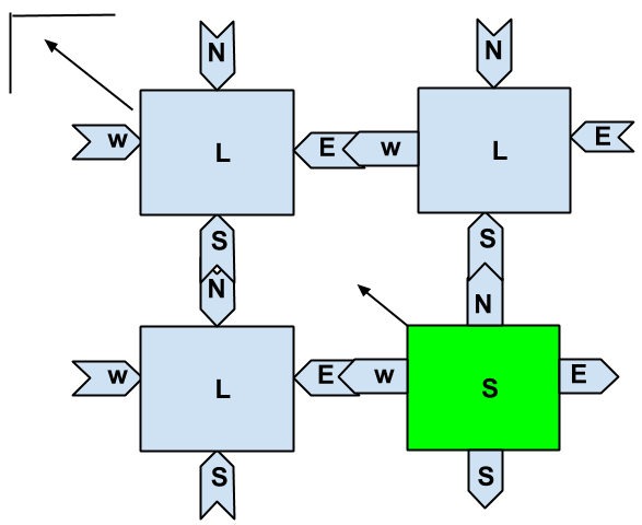
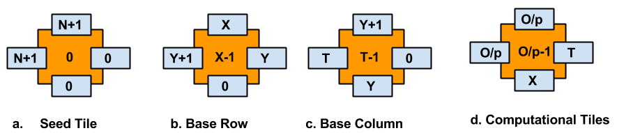
Each tile has label L and some glue on each side. Each glue has some strength. Two adjacent tiles can join if and only if their glue matches. While assembly, a tile can be transformed but cannot be rotated. A tile system can be represented as where T is the tile system, S is the seed configuration of this tile assembly, g is the glue strength of an edge with configuration {N E S W} (N-North, E-East, S-South, W-West) as shown in Fig 1 and (always is the threshold temperature. A tile file is created using different tile types depending on g and . Xgrow simulator takes a tile file as input and simulates it depending upon the tile types and their glues. In any tile file we need to specify the following basic parameters.
-
1.
Total number of tile types
-
2.
Total number of glues
-
3.
Configuration of each tile
-
4.
Seed tile
-
5.
and parameters that measures free energy and entropy
3 PIXEL PATTERNS USING DNA TILE ASSEMBLY
Every image is made up of pixels. To generate image using tile assembly, one can consider each pixel as a tile. Assigning each tile with the pixel color, image block can be easily generated by combining each tile. If we consider image block with dimensions NM pixels then NM tile types are needed to generate the image block by tiles assembly. This way is trivial and inefficient for image with large dimensions as it needs large number of tiles. To simplify the problem, consider an image with some fixed pixel patterns. If there is some specific pattern, for which tile sets can be developed such that it can generate complete image, then this can be more feasible and efficient. With this idea, here two basic patterns in image block is considered. If image has cyclic blocks of uniform shift or non uniform shifts, then it can be generated by assembly of few tiles set with uniform and non uniform shift tile sets respectively.
3.1 Uniform Shift Generator
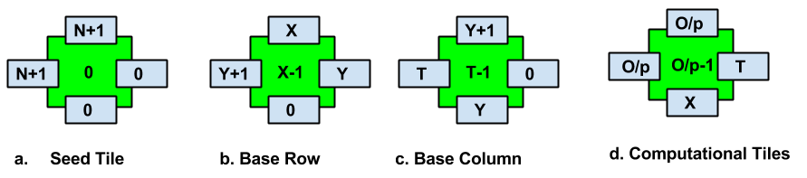
Consider image block with uniform shift, then by developing a tile set for self assembly of the uniform shift patterns complete image block can be generated. For uniform shift following basic tile types are required.
-
1.
Seed Tile
-
2.
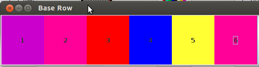
Base Row
-
3.
Base Column
-
4.
Computational Tiles
Depending on uniform shift value, each row will be shifted uniformly. Total number of tiles required for uniform shift generation is given by theorem 3.1.
Theorem 3.1
Proof
Consider a tile system over with seed tile configuration as shown in Fig 2. Total number of base row, base column and computational tiles gives overall tile sets required. For uniform shift generation, base row tiles are N, base column is N-1 and computational tiles are N. Hence total tile required are N+N-1+N. Therefore minimum number of tiles types needed are 3N-1.
| Type of tiles | Number of tiles |
|---|---|
| Seed tiles | 1 |
| Base row tile | N-1 |
| Base column tile | N-1 |
| Computational tile | N |
| Total tiles | 3N-1 |
Example 1
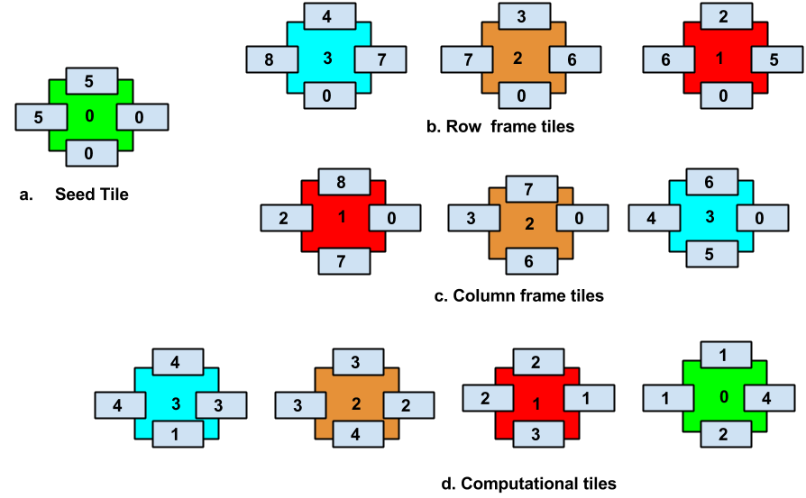
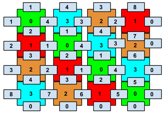
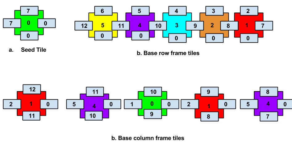
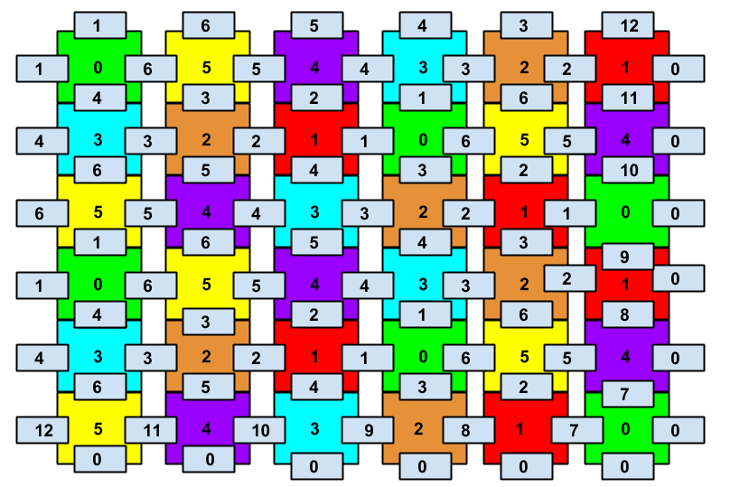
Let us consider a tile set for and Shift value Tile set file generated by using DNA Image Pro as shown in Fig 3 is given below. Tile assembly generated is shown in Fig 4
%seed tile
{5 0 0 5 }(-33554177)
%First row. (bottom boundary row)
{2 5 0 6 }(-16842752)
{3 6 0 7 }(-33554177)
{4 7 0 8 }(-16842752)
%First column. (Right most column)
{6 0 5 4 }(-16842752)
{7 0 6 3 }(-33554177)
{8 0 7 2 }(-16842752)
%Rule tiles
{1 4 2 1 }(-33554177)
{2 1 3 2 }(-16842752)
{3 2 4 3 }(-33554177)
{4 3 1 4 }(-16842752)
In the example 1, the seed tile is with configuration for For base row where and
For tile is
tile is
X=4 tile is {4,7,0,8}
For Base Column is with configuration {Y+1,0,Y,T}, Y= X+N-1 where , and T = T+N if T 1.
First we will have T=1
Now for X=2, Y=5, T=4 which will be {6,0,5,4}.
for X=3, Y=6, T=3 which will be {7,0,6,3}
for X=4, Y=7, T=2 which will be {8,0,7,2}
For Computational tiles we have configuration {Op,T,X,Op}, for , and T = T+N if T1,
and Op = Op+N if Op 1.
Let T=1.
For X =1, T = 3, Op = 4 which will be {4,3,1,4}.
for X =2, T = 4, Op = 1 which will be {1,4,2,1}.
for X =3, T = 1, Op = 2 which will be {2,1,3,2}.
for X =4, T = 2, Op = 3 which will be {3,2,4,3}.
3.2 Non-Uniform Shift Generator General tile set
Consider block of non uniform shifts in image block, generation of tile assembly for non uniform shift image block can be generated.For each row different shifts values can be assigned. For Given base row of length N and Non-Uniform Shift array S, We can represent the tile set using following type of tiles:
-
1.
Seed Tile
-
2.
Base Row
-
3.
Base Column
-
4.
Computational Tiles
Generalized tiles for each type are N = Base Row Length and S = Array of Shift Value.
Theorem 3.2
Proof
Consider a tile system over with seed tile configuration as shown in Fig 5. For non uniform shift, each N-1 base row tiles and N-1 column tiles are shifted non uniformly with computational tiles N S, therefore total tiles are .
| Type of Tiles | Number of tiles |
|---|---|
| Seed tiles | 1 |
| Base row tile | N-1 |
| Base column tile | N-1 |
| Computational tile | N S |
| Total tiles | 2(N-1)+ NS |
3.3 Row Transformation
Row transformation on pixel configuration is considered in this section. Transformation of the base row tiles will effect the shift generation of the tile assembly. Let the image with P configuration be transformed to image with Q configuration by some transformation T. This will result in the tile assembly transformation. Lemma 1 gives the method to apply the row transformation of the DNA tiles using shift operator.
Lemma 1
Row transformation of a DNA tile set of image block can be obtained by where S is the shift operator and N is number of tiles in the base row.
3.4 Image Tile generator
For any input image block, one can generate the tile assembly. By rendering the image selected, the tile sets are generated. There are two methods to generate the image.
-
1.
Rapid image generator
-
2.
Normal image generator
Unlike normal image generation, rapid image generator will compress the original image in 3232 and generate the tile file for compressed image. Normal image generator will not compress the input image so it will use more tile types then rapid image generator. Image will be generated at high speed by using rapid generator but it will decrease the quality of image. Figure 8 is the original image which is to be generated by using rapid image generation. Figure 9 shows the image generated by tile assembly using rapid image generation.


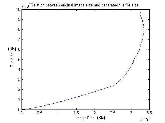
To estimate the tile files required for particular image, Fig 10 shows the relation between image size and size of tiles required. As the image size increases, number of tiles required increases.
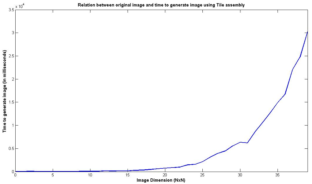
To estimate the time required to generate particular image by tile assembly, Fig 11 shows the relation between image size and time required to generate the image. As the image dimension increases, time required for tile assembly increases.
4 DNA Image Pro: GUI OVERVIEW
DNA Image Pro is used to generate tile file for different types of images and it also provides new version of Xgrow. It has menu with the following option:
-
–
Uniform Shift Generator
-
–
Non Uniform Shift Generator
-
–
Transformation Generator
-
–
Image Tile generator
-
–
Run a Tile File
4.1 Uniform Shift Generator
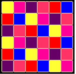
This will generate the NN tile sets on the basis of the seed tile sets specified. User should specify the flakes tile set that is the base row for the tile assembly. It will generate the tile assembly uniformly with given value of the shift operator. It will have uniform pattern for the tile assembly. Figure 12 shows the image tile generated by DNA Image Pro with number of tiles N = 6 and uniform shift operator S = 2. Figure 13 is the result of tile set simulation in Xgrow for the example N = 6 and uniform shift operator S = 2.
4.2 Non Uniform Shift Generator
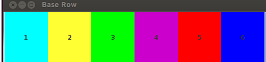
It is similar to uniform generator. This will generate the NN tile sets on the basis of the seed tile sets specified. User should specify the flakes tile set that is the base row for the tile assembly. It will generate the tile assembly non uniformly with given value of the shift operators. Unlike uniform generator, there will be shift operator for each row. So the number of shift operator will be N-1. Figure 14 shows the image tile generated by DNA Image Pro with number of tiles N = 6 and non uniform shift operator S = [1,2,3,1,2]. Figure 15 is the result of tile set simulation in Xgrow for the example N = 6 and uniform shift operator S = [1,2,3,1,2].
4.3 Transformation Generator
It is similar to non-uniform generator along with the row transformation on the base tiles. This will generate the NN tile sets on the basis of the seed tile sets specified. It will generate the tile assembly by applying the row transformation on the base tile set using the shuffle value provided.
4.4 Run a Tile File
This option is used to execute a tile file generated by DNA Image Pro in Xgrow. User need to select a file and it will execute it in Xgrow.
5 OPEN PROBLEM
We are considering each pixel of an image as unique tile type. So if we want to generate an image with width W and length L, we would require WL tile types. For any given image, optimization of the tile set assembly is still an open challenge. One can use the redundancy in the image to search for the minimal set of tiles needed to generate the image.
6 Software Availability
The software (source code), installers, user manual, installation guide and other related materials can be downloaded from
http://www.guptalab.org/dnaimagepro/.
Acknowledgments
Authors would like to thank Paul W. K. Rothemund for useful comments on the paper.
References
- [1] Doty, D.: Theory of algorithmic self-assembly. Communications of the ACM 55(12), 78–88 (2012)
- [2] Fujibayashi, K., Hariadi, R., Park, S.H., Winfree, E., Murata, S.: Toward reliable algorithmic self-assembly of DNA tiles: A fixed-width cellular automaton pattern. Nano Letters 8(7), 1791–1797 (2007)
- [3] He, Y., Chen, Y., Liu, H., Ribbe, A.E., Mao, C.: Self-assembly of hexagonal DNA two-dimensional (2d) arrays. Journal of the American Chemical Society 127(35), 12202–12203 (2005)
- [4] He, Y., Su, M., Fang, P.a., Zhang, C., Ribbe, A.E., Jiang, W., Mao, C.: On the chirality of self-assembled DNA octahedra. Angewandte Chemie 122(4), 760–763 (2010)
- [5] He, Y., Ye, T., Su, M., Zhang, C., Ribbe, A.E., Jiang, W., Mao, C.: Hierarchical self-assembly of DNA into symmetric supramolecular polyhedra. Nature 452(7184), 198–201 (2008)
- [6] LaBean, T.H., Yan, H., Kopatsch, J., Liu, F., Winfree, E., Reif, J.H., Seeman, N.C.: Construction, analysis, ligation, and self-assembly of DNA triple crossover complexes. Journal of the American Chemical Society 122(9), 1848–1860 (2000)
- [7] Lin, C., Liu, Y., Rinker, S., Yan, H.: DNA tile based self-assembly: Building complex nanoarchitectures. ChemPhysChem 7(8), 1641–1647 (2006)
- [8] Liu, D., Park, S.H., Reif, J.H., LaBean, T.H.: DNA nanotubes self-assembled from triple-crossover tiles as templates for conductive nanowires. Proceedings of the National Academy of Sciences of the United States of America 101(3), 717–722 (2004)
- [9] Park, S.H., Barish, R., Li, H., Reif, J.H., Finkelstein, G., Yan, H., LaBean, T.H.: Three-helix bundle DNA tiles self-assemble into 2d lattice or 1d templates for silver nanowires. Nano letters 5(4), 693–696 (2005)
- [10] Seeman, N.C.: Nucleic acid junctions and lattices. Journal of Theoretical Biology 99(2), 237 – 247 (1982), http://www.sciencedirect.com/science/article/pii/0022519382900029
- [11] Winfree, E.: The xgrow simulator (2003), http://www.dna.caltech.edu/Xgrow
- [12] Winfree, E.: Algorithmic self-assembly of DNA. Ph.D. thesis, California Institute of Technology (1998)
- [13] Zhang, J., Liu, Y., Ke, Y., Yan, H.: Periodic square-like gold nanoparticle arrays templated by self-assembled 2D DNA nanogrids on a surface. Nano letters 6(2), 248–251 (2006)