Gate-controllable magneto-optic Kerr effect in layered collinear antiferromagnets
Abstract
Using symmetry arguments and a tight-binding model, we show that for layered collinear antiferromagnets, magneto-optic effects can be generated and manipulated by controlling crystal symmetries through a gate voltage. This provides a promising route for electric field manipulation of the magneto-optic effects without modifying the underlying magnetic structure. We further demonstrate the gate control of magneto-optic Kerr effect (MOKE) in bilayer MnPSe3 using first-principles calculations. The field-induced inversion symmetry breaking effect leads to gate-controllable MOKE whose direction of rotation can be switched by the reversal of the gate voltage.
pacs:
75.50.Ee,75.70.Ak,75.75.-c,78.20.Ls,85.70.SqMagneto-optic effects are one of the defining features of time-reversal ( symmetry breaking in matter. Usually, the symmetry is broken either by an external magnetic field, or by the spontaneous appearance of a macroscopic magnetization such as in ferromagnets. Similar to their ferromagnetic counterparts, the symmetry is also broken in antiferromagnets. However, because of their vanishing net magnetization one would naively expect an absence of magneto-optic effects in antiferromagnets. This assumption has been recently challenged by the theoretical demonstration of a rather large magneto-optic Kerr effect (MOKE) in certain non-collinear antiferromagnets with zero net magnetization Feng et al. (2015). This effect is closely related to the anomalous Hall effect predicted in the same class of materials Chen et al. (2014); Kübler and Felser (2014), both of which are dictated by the absence of certain crystal symmetries. The appearance of magneto-optic effects in antiferromagnets is of intrinsic interest, since it would allow direct detection of the magnetic order and therefore could be useful for antiferromagnets-based memory devices Jungwirth et al. (2016).
While non-collinear antiferromagnets have been the focus of recent interest Feng et al. (2015); Chen et al. (2014); Kübler and Felser (2014), in this Letter we show that magneto-optic effects can also exist in the more commonly available collinear antiferromagnets. We start by analyzing the general symmetry requirements for magneto-optic effects, and demonstrate the symmetry principles by constructing a tight-binding model with a collinear Néel type order. We show that, contrary to the general belief, lifting the spin degeneracy of the energy bands is not a sufficient condition to generate magneto-optic effects; it is the crystal symmetry that actually controls these effects.
Based on this understanding, we predict that a perpendicular electric field can be used to generate and control the MOKE in layered antiferromagnets using first-principles calculations. Recent theoretical and experimental progress has identified several layered compounds as promising candidates to host magnetism in their thin-film limit Casto et al. (2015); Sivadas et al. (2015); Williams et al. (2015); McGuire et al. (2015); Lin et al. (2016); Li et al. (2013). One of them is MnPSe3, a semiconductor with collinear antiferromagnetic order within each layer. We show that the field-induced inversion () symmetry breaking in bilayer MnPSe3 gives rise to a MOKE whose direction of rotation can be switched by the reversal of the gate voltage. Our result indicates that layered antiferromagnets would provide a very promising platform to explore gate-controllable magneto-optic effects.
As symmetries play an important role in magneto-optic effects Eremenko et al. (1992), we begin our discussion with a general symmetry analysis. Magneto-optic effects are closely related to the AC Hall effect [see Eq. (5) below], which refers to the appearance of a transverse AC current in response to an optical field in the longitudinal direction. Therefore, we can use the following pseudo-vector
| (1) |
to characterize magneto-optic effects. If the material possesses symmetry, is clearly constrained to be zero. Both ferromagnets and antiferromagnets break symmetry. However, it is possible that the material might have a combined symmetry of and some crystal symmetry , which can force to be zero even if symmetry is broken. To elucidate this, consider an antiferromagnets with symmetry. One such example is shown in Fig. 1(a). Under symmetry, is unaffected, whereas changes sign. It then follows from Eq. (1) that changes sign under the symmetry operation. This forces to be zero and suppresses any magneto-optic effects. Using a similar analysis, it is straightforward to show that for two-dimensional systems both symmetry and symmetry also suppress magneto-optic effects, where is the mirror reflection perpendicular to the - plane, and is the in-plane inversion symmetry. Thus, by breaking these crystal symmetries, magneto-optic effects can be generated in antiferromagnets. This is the key to our gate controllable MOKE.
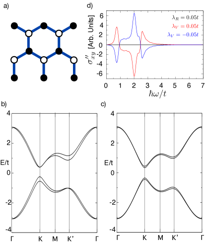
Armed with the above insight, we now consider a specific example, a honeycomb lattice with a collinear Néel type order, as shown in Fig. 1(a). The Hamiltonian is given by
| (2) |
The first term is the nearest neighbor hopping. The second term is the intrinsic spin-orbit coupling (SOC), which is needed for any magneto-optic effects. Here, , where and are the unit vectors of the two bonds connecting site to , and is the spin Pauli matrix. Along with preserving the symmetry, this term also preserves both and symmetries. The third term breaks symmetry via a staggered Zeeman field, mimicking the Néel order with an out-of-plane easy axis. We note that this term can be dynamically generated by local interactions, Rachel and Le Hur (2010); Hohenadler et al. (2011). Within the mean-field approximation, and are related by where is the spontaneous magnetic moment. Thus, our results are also valid for interacting systems with robust magnetic ordering. One can verify that the system is invariant under the symmetry. This Hamiltonian is identical to the one proposed by Kane and Mele for the quantum spin Hall effect Kane and Mele (2005), except the term. As we are interested in the properties of a topologically trivial antiferromagnetic insulator, we will work in the strong exchange limit where the band gap is dominated by ().
To analyze the role of crystal symmetries, we add two symmetry breaking terms to the Hamiltonian
| (3) |
The Rashba SOC term () breaks the symmetry, and the staggered sublattice potential () breaks the in-plane inversion symmetry. Figure 1(b) and (c) show the energy bands obtained for two representative cases where the symmetry is broken. In cases I we switch on only the Rashba term (), whereas in case II only the staggered sublattice potential is turned on (). It is clear that the effect of these symmetry breaking terms is to lift the spin degeneracy of the bands. We also note that and valleys are no longer degenerate. This is not a consequence of symmetry breaking, and in fact, they remain non-degenerate even when the symmetry breaking terms are removed. The breaking of the valley degeneracy arises from the interaction of the antiferromagnetic order and the intrinsic SOC Li et al. (2013).
Next, we calculated the optical Hall conductivity using the Kubo-Greenwood formula Yao et al. (2004); Ebert (1996),
| (4) |
where is the Fermi-Dirac distribution function, is the energy of the th band, is the photon energy, and is an adjustable smearing parameter with units of energy. Figure 1(d) shows the imaginary part of , denoted by . Even though the bands are spin-split in both cases, we can see that is identically zero for case I and is non-zero only for case II. To understand this we further analyze the symmetry properties of the system. We note that even though the system is invariant under , the symmetry is already broken by the out-of-plane magnetic order. In case I, although the Rashba term breaks symmetry, the system still possesses symmetry. As we discussed earlier, it suppresses any magneto-optic effects. This shows that even though the bands are spin-split, the underlying crystal symmetries can force the magneto-optic effects to vanish. In case II, the staggered sublattice potential breaks both and symmetries, it therefore lifts all symmetry constraints on magneto-optic effects, making it non-zero.
In addition, we also find that upon the reversal of the staggered sublattice potential, changes its sign. It can be verified that the process of reversing the sign of the staggered sublattice potential is equivalent to switching the sublattices and reversing the spins. This operation is nothing but the symmetry operation. However, we have already discussed that symmetry operation reverses the sign of , which is indeed what we find. On the other hand, if natural birefringence also exist in the system, their contribution would not flip sign upon the reversal of the sublattice potential. This property can be used to distinguish between magneto-optical effects and natural birefringence.
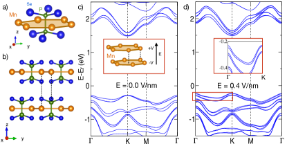
While crystal symmetries are difficult to control in bulk materials, it has been demonstrated that gating can be an effective tool to break the inversion symmetry in 2D materials Zhang et al. (2009); Mak et al. (2009); Wu et al. (2013); Sui et al. (2015); Shimazaki et al. (2015). In the following using first-principles method we demonstrate the idea of gate-controllable MOKE using bilayer MnPSe3 as an example. In its bulk form, MnPSe3 is a layered compound with weak interlayer Van der Waals interaction. The crystal structure of MnPSe3 monolayer is shown in Fig. 2(a). The magnetic ions (Mn) form a honeycomb lattice within each layer, and each of them is octahedrally coordinated by six Se atoms from its three neighboring (P2Se6) ligands, with the centers of the hexagons occupied by the P2 groups. The Mn ions are in a half-filled state, making MnPSe3 a strong antiferromagnet. We also find that the system has an easy axis along the -direction, with the spins taking a Néel-type texture. The bilayer considered here is made of these monolayer units with a stacking order similar to the bulk form [see Fig. 2(b)]. There are two Mn atoms in each layer of the bilayer unit cell. In the top layer, while one Mn atom lies on top of an Mn atom in the bottom layer, the second Mn atom lies on top of the P atoms in bottom layer. The spins of the Mn ions from the two layers are antiferromagnetically coupled. It can be verified that bilayer MnPSe3 has symmetry, hence, no magneto-optic effect is allowed.
This symmetry can be broken by a perpendicular electric field. We first look at the effect of such a field on the band structure of bilayer MnPSe3. The details of first-principles calculations are described in Ref. sup . Figure 2(c) shows the band structure in the absence of an electric field. Because of the presence of the symmetry, the spin-up and spin-down bands are degenerate at each point, making the material magneto-optically inactive. However, upon the application of a field (0.4 V/nm), the spin degeneracy of the bands is lifted, symptomatic of symmetry breaking [see Fig. 2(d) and its insert].
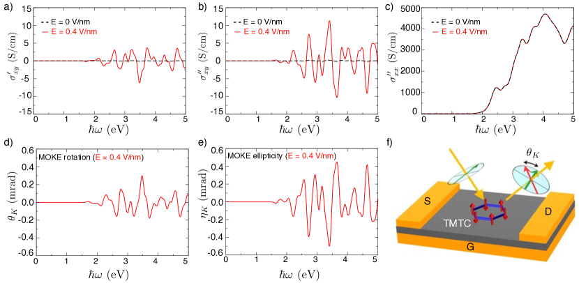
Thus, on the application of a perpendicular electric field, we expect bilayer MnPSe3 to become magneto-optically active. Figure 3(a)-(c) show the optical conductivity tensor obtained from the calculation of maximally localized Wannier functions Marzari and Vanderbilt (1997); Souza et al. (2001); Mostofi et al. (2008). We can see that is zero when the field is zero (black curves). It becomes non-zero for a finite field (red curves), as expected. We have also verified that the reversal of the field reverses the sign of sup . The longitudinal conductivity , on the other hand, is almost invariant under the application of a field [see Fig. 3(c)]. This is not surprising as measures the average absorption of right- and left-circularly polarized light Feng et al. (2015). We note that the oscillatory behavior of as a function of is already observed in our tight-binding model [see Fig. 1(d)].
To quantify the field-induced MOKE, we have calculated the complex polar Kerr angle. For simplicity, we assume that the incoming light is perpendicular to the surface, and the sample is placed on a wedged substrate such that there is no reflection from the substrate in the perpendicular direction. In the thin film limit the Kerr angles are given by Kim et al. (2007); Valdés Aguilar et al. (2012)
| (5) |
where specifies the rotation angle of the major axis of the linearly polarized light, specifies the ratio of the minor to the major axis of the light, is the refractive index of the substrate, is the impedance of free space and the thickness of bilayer MnPSe3 (10.3 Å). Figure 3(d) and (e) show the computed MOKE angles for a wedged SiO2 substrate (). For field strength of 0.4 V/nm, can reach up to 0.3 mrad, which is well within the current detection limit Kato et al. (2004); Lee et al. (2016). Note that due to the oscillatory behavior of , the size of the Kerr angle has a strong dependence on the smearing parameter, and can be made larger in high-quality samples sup . The smearing parameter eV chosen here corresponds to a carrier relaxation time of 6.5 fs, which is in the realistic range for layered transition metal chalcogenides Strait et al. (2014). The generation of the MOKE in a magneto-optically inactive material using gate voltage is an important distinction from previous work Feng et al. (2015).
We have also studied the field-dependence of the MOKE in monolayer MnPSe3. Similar to bilayers, monolayer MnPSe3 also has symmetry. However, we find that the MOKE angle remains negligibly small in monolayers upon the application of an electric field of the same strength sup . This is due to the fact that in monolayer MnPSe3, the inversion symmetry breaking is realized by creating a potential difference between the top and bottom PSe3 layers, which is “felt” by the Mn atom through the interaction between the Mn d orbitals and the Se p orbitals. This is a much weaker effect compared to the case of bilayers where the Mn atoms in different layers directly feel the effect of the electric field.
Our predicted gate-controllable MOKE has important implications in both fundamental research and practical applications. As the observed MOKE is very sensitive to the underlying magnetic order, it can be used to identify the magnetic ground state. Not only can this method distinguish between ferromagnets and antiferromagnets, but it can be also used to distinguish among different antiferromagnetic orders, such as Néel, zigzag and stripy order on a honeycomb lattice Sivadas et al. (2015), supplemented by symmetry analysis and band structure calculations. This is especially valuable for 2D materials since neutron scattering is ineffective for these materials due to the small scattering cross section. Furthermore, the sensitivity of the MOKE to the magnetic order can be exploited for magnetic information storage. For instance, the reversal of the Néel vector will result in a change of sign of the observed MOKE. Thus, the information encoded in the Néel vector can be extracted using this gate-controlled MOKE in antiferromagnets.
We are grateful to Hua Chen, Matthew W. Daniels, Tony Heinz, Kin Fai Mak, David Mandrus, Jiaqiang Yan, and Xiaodong Xu for stimulating discussions. We would also like to thank Valentino Cooper, Ji Feng and Xiao Li for their computational inputs. We are indebted to the anonymous reviewers for providing insightful comments on an earlier version of this work. This work was supported by the Air Force Office of Scientific Research under Grant No. FA9550-12-1-0479 and FA9550-14-1-0277, and by the National Science Foundation under Grant No. EFRI-1433496. S.O. acknowledges support by the U.S. Department of Energy, Office of Science, Basic Energy Sciences, Materials Sciences and Engineering Division. This research used resources of the National Energy Research Scientic Computing Center, which is supported by the DOE Office of Science under Contract No. DE-AC02-05CH11231. D.X. also acknowledges support from a Research Corporation for Science Advancement Cottrell Scholar Award.
References
- Feng et al. (2015) W. Feng, G.-Y. Guo, J. Zhou, Y. Yao, and Q. Niu, Phys. Rev. B 92, 144426 (2015).
- Chen et al. (2014) H. Chen, Q. Niu, and A. H. MacDonald, Phys. Rev. Lett. 112, 017205 (2014).
- Kübler and Felser (2014) J. Kübler and C. Felser, EPL (Europhysics Letters) 108, 67001 (2014).
- Jungwirth et al. (2016) T. Jungwirth, X. Marti, P. Wadley, and J. Wunderlich, Nature Nanotech. 11, 231 (2016).
- Casto et al. (2015) L. D. Casto, A. J. Clune, M. O. Yokosuk, J. L. Musfeldt, T. J. Williams, H. L. Zhuang, M.-W. Lin, K. Xiao, R. G. Hennig, B. C. Sales, J.-Q. Yan, and D. Mandrus, APL Mater. 3, 041515 (2015).
- Sivadas et al. (2015) N. Sivadas, M. W. Daniels, R. H. Swendsen, S. Okamoto, and D. Xiao, Phys. Rev. B 91, 235425 (2015).
- Williams et al. (2015) T. J. Williams, A. A. Aczel, M. D. Lumsden, S. E. Nagler, M. B. Stone, J.-Q. Yan, and D. Mandrus, Phys. Rev. B 92, 144404 (2015).
- McGuire et al. (2015) M. A. McGuire, H. Dixit, V. R. Cooper, and B. C. Sales, Chem. Mater. 27, 612 (2015).
- Lin et al. (2016) M.-W. Lin, H. L. Zhuang, J. Yan, T. Z. Ward, A. A. Puretzky, C. M. Rouleau, Z. Gai, L. Liang, V. Meunier, B. G. Sumpter, and et al., J. Mater. Chem. C 4, 315 (2016).
- Li et al. (2013) X. Li, T. Cao, Q. Niu, J. Shi, and J. Feng, Proc. Natl. Acad. Sci. 110, 3738 (2013).
- Eremenko et al. (1992) V. V. Eremenko, N. F. Kharchenko, Y. G. Litvinenko, and V. M. Naumenko, Magneto-optics and spectroscopy of antiferromagnets (Springer-Verlag, New York, 1992).
- Rachel and Le Hur (2010) S. Rachel and K. Le Hur, Phys. Rev. B 82, 075106 (2010).
- Hohenadler et al. (2011) M. Hohenadler, T. C. Lang, and F. F. Assaad, Phys. Rev. Lett 106, 100403 (2011).
- Kane and Mele (2005) C. L. Kane and E. J. Mele, Phys. Rev. Lett. 95, 146802 (2005).
- Yao et al. (2004) Y. Yao, L. Kleinman, A. H. MacDonald, J. Sinova, T. Jungwirth, D.-s. Wang, E. Wang, and Q. Niu, Phys. Rev. Lett. 92, 037204 (2004).
- Ebert (1996) H. Ebert, Reports on Progress in Physics 59, 1665 (1996).
- Momma and Izumi (2011) K. Momma and F. Izumi, J. Appl. Cryst. 44, 1272 (2011).
- Zhang et al. (2009) Y. Zhang, T.-T. Tang, C. Girit, Z. Hao, M. C. Martin, A. Zettl, M. F. Crommie, Y. R. Shen, and F. Wang, Nature 459, 820 (2009).
- Mak et al. (2009) K. F. Mak, C. H. Lui, J. Shan, and T. F. Heinz, Phys. Rev. Lett. 102, 256405 (2009).
- Wu et al. (2013) S. Wu, J. S. Ross, G.-B. Liu, G. Aivazian, A. Jones, Z. Fei, W. Zhu, D. Xiao, W. Yao, D. Cobden, and X. Xu, Nat Phys 9, 149 (2013).
- Sui et al. (2015) M. Sui, G. Chen, L. Ma, W.-Y. Shan, D. Tian, K. Watanabe, T. Taniguchi, X. Jin, W. Yao, D. Xiao, and Y. Zhang, Nat Phys 11, 1027 (2015).
- Shimazaki et al. (2015) Y. Shimazaki, M. Yamamoto, I. V. Borzenets, K. Watanabe, T. Taniguchi, and S. Tarucha, Nat Phys 11, 1032 (2015).
- (23) See Supplemental Material at for technical details of the calculation, and additional information .
- Marzari and Vanderbilt (1997) N. Marzari and D. Vanderbilt, Phys. Rev. B 56, 12847 (1997).
- Souza et al. (2001) I. Souza, N. Marzari, and D. Vanderbilt, Phys. Rev. B. 65, 035109 (2001).
- Mostofi et al. (2008) A. Mostofi, J. Yates, L. Young-See, I. Souza, D. Vanderbilt, and N. Marzari, Comp. Phys. Commun. 178, 685 (2008).
- Kim et al. (2007) M.-H. Kim, G. Acbas, M.-H. Yang, I. Ohkubo, H. Christen, D. Mandrus, M. A. Scarpulla, O. D. Dubon, Z. Schlesinger, P. Khalifah, and J. Cerne, Phys. Rev. B 75, 214416 (2007).
- Valdés Aguilar et al. (2012) R. Valdés Aguilar, A. V. Stier, W. Liu, L. S. Bilbro, D. K. George, N. Bansal, L. Wu, J. Cerne, A. G. Markelz, S. Oh, and N. P. Armitage, Phys. Rev. Lett. 108, 087403 (2012).
- Kato et al. (2004) Y. K. Kato, R. C. Myers, A. C. Gossard, and D. D. Awschalom, Science 306, 1910 (2004).
- Lee et al. (2016) J. Lee, K. F. Mak, and J. Shan, Nat Nano 11, 421 (2016).
- Strait et al. (2014) J. H. Strait, P Nene, and F. Rana, Phys. Rev. B 90, 245402 (2014).