First Evaluation of Dynamic Aperture at Injection for FCC-hh111This Research and Innovation Action project submitted to call H2020-INFRADEV-1-2014-1 receives funding from the European Union’s H2020 Framework Program under grant agreement no. 654305.
Abstract
In the Hadron machine option, proposed in the context of the Future Circular Colliders (FCC) study, the dipole field quality is expected to play an important role, as in the LHC. A preliminary evaluation of the field quality of dipoles, based on the Nb3Sn technology, has been provided by the magnet group. The effect of these field imperfections on the dynamic aperture, using the present lattice design, is presented and first tolerances on the b3 and b5 multipole components are evaluated.
I Introduction
The main dipole magnets are critical elements for the machine performance in the case of LHC and of FCC-hh. In particular their field quality impacts the long term stability of the particles in the machine. The behavior of the particles in presence of magnet imperfections cannot be cured by dedicated feedback, therefore, it is important to know them in advance and to correct them if they reduce, below the safety limit, the Dynamic Aperture (DA) of the machine, defined as the region in phase space where stable motion occurs. As in the LHC also in the FCC-hh different magnets are expected to play a role in the definition of the DA at injection and at collision energy. At injection the main dipole field quality is the major contributor to the reduction of DA in LHC injLHC , while at collision the triplet field quality and the beam-beam effects are the major sources of the DA reduction colLHC . The baseline injection energy for FCC-hh has been fixed at 3.3 TeV, which gives more or less the same ratio between injection and collision energy as in the LHC. In the following we discuss the first estimate of main dipole field quality and magnet specifications, using DA as figure of merit. The optics used for this study are briefly introduced in section II. In section III the first estimate of dipole field quality together with the arc magnets specifications are presented. The first evaluation of tolerances on b3 and b5 using dynamic aperture and detuning with amplitude and momentum are reported in section IV and V. Finally, possible improvements of these tolerances estimations are qualitatively analyzed in section VI.
II Optics
The current layout of the FCC-hh ring (see Fig. 1) is made of 4 short arcs (SAR), 4 long arcs (LAR), 6 long straight sections (LSS) and 2 extended straight sections (ESS). The main ring parameters and the main functionality of each of the insertions are reported in AntIpac16 .
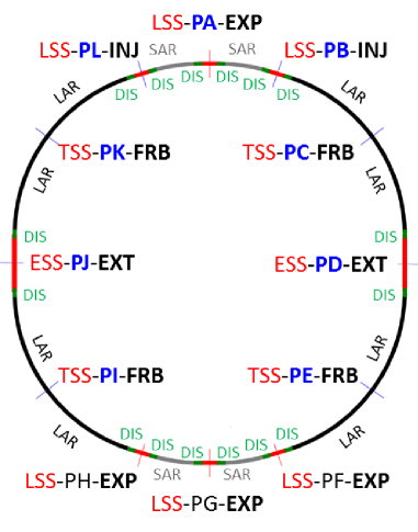
We have considered different versions of insertion optics for the Interaction Region (IR) and the momentum collimation, as far as they became available, while keeping the same arc, injection, extraction and betatron collimation optics.
Three versions of the IR insertion optics have been considered. The first version has been designed with a L∗ of 36 m RomIpac15 , a of 3.5 m is used for the study of DA at injection and the ultimate of 0.3 m at collision (in the following called v2). In the second version of the IR optics the value at injection has been increased to 4.6 m to ensure that the aperture bottleneck, and as a consequence the collimation settings, are dominated by the arcs and not the IRs (in the following called v4). Finally, the third version of the IR has been designed with a L∗ of 45 m, due to experimental detector constraints (in the following called v5 AndyFCC ).
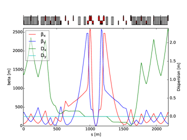
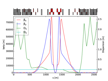
Figure 2 shows the optics function of IR v4 at injection and of IR v5 at collision. In the IR v4 and v5 the phase advance between the IPs A and G and the first focusing/defocusing sextupole of the SAR is respectively adjusted to 90∘ modulo 180∘ in the horizontal/vertical plane. In all optics versions, the first order chromaticity is corrected () by two sextupole families distributed in the SAR and LAR.
Three versions have been used for the momentum collimation optics, as well: the first two are slightly different versions of simple FODO cells, which have a maximum dispersion of 5 and 4 meters (called fodo90 v1 and fodo90 v2, respectively). The third version of the optics has been designed by scaling the betatron functions and the lengths from the LHC, using the factor (ratio between the nominal beam energy of FCC and of LHC). A number of FODO cells with 90∘ phase advance has been added downstream to fill the 4.2 km foreseen for the ESS insertion region (in the following called lhc v1). The concept of the injection and extraction insertions can be found in BartIpac15 , BartFCC16 , and the present betatron collimation design is described in FiasIpac16 .
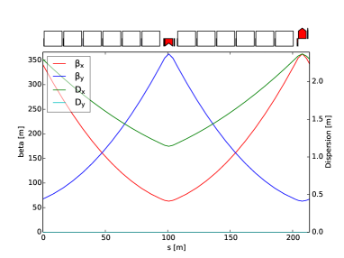
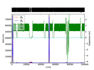
The FODO cells of the arcs are optimized to have the largest filling ratio Ant15 , IoIpac15 (Fig. 3 (a)). The phase advance in the FODO cells is exactly 90∘ in the SAR whereas it is 90∘ in the LAR. The value of is adjusted to tune the whole ring. In particular for the optics considered in this study the value of changes up to 1∘, according to the IR and momentum collimation optics version. A dipole is removed at the middle of the LAR to save some space for the technical straight sections (TSS). The optics of the whole ring is shown in Fig. 3 (b).
III Dipole Field Quality and Magnets specifications
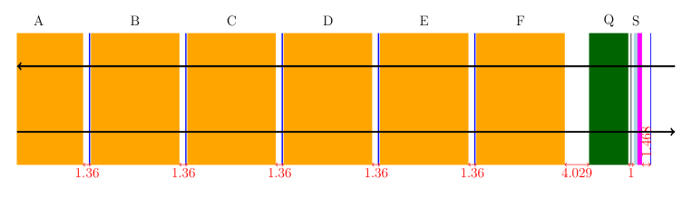
Currently the total arc cell length is 214 m with 12 dipoles and 12 spool pieces for the correction of the b3 component of the main dipole, one attached to each dipole of the cell (as shown in Fig.4). Both the dipole and the spool piece correctors have the same length of the LHC corresponding magnets. The same interconnection lengths between two dipoles, and between the main dipole and the main quadrupoles have been estimated to be feasible by the magnet group Eziofcc . Octupoles for Landau damping and octupole or decapole correctors are not included in the current version of the lattice layout, neither are skew sextupoles. The dipoles are set at almost their maximum strength (16 T). At this field and at a reference radius of 17 mm a first estimate of the expected field quality for the injection and the collision energy has been provided by the magnets group Eziofcc , as shown in Table 1.
| systematic | uncertainty | random | ||
| Normal | inj | col | ||
| 3 | -5 | 20 | 0.781 | 0.781 |
| 4 | 0 | 0 | 0.065 | 0.065 |
| 5 | -1 | -1.5 | 0.074 | 0.074 |
| 6 | 0 | 0 | 0.009 | 0.009 |
| 7 | -0.5 | 1.3 | 0.016 | 0.016 |
| 8 | 0 | 0 | 0.001 | 0.001 |
| 9 | -0.1 | 0.05 | 0.002 | 0.002 |
| Skew | ||||
| 3 | 0 | 0 | 0.256 | 0.256 |
| 4 | 0 | 0 | 0.252 | 0.252 |
| 5 | 0 | 0 | 0.05 | 0.05 |
| 6 | 0 | 0 | 0.04 | 0.04 |
| 7 | 0 | 0 | 0.007 | 0.007 |
| 8 | 0 | 0 | 0.007 | 0.007 |
| 9 | 0 | 0 | 0.002 | 0.002 |
| 10 | 0 | 0 | 0.001 | 0.001 |
where represent the magnetic field at the reference radius , for the principal harmonics. The subscript refers to dipole, to a quadrupole and so on. Each multipole harmonics entering in the dipole field expansion ( and ) is modeled as the sum of three contributions:
| (2) |
where and denote the random numbers with Gaussian distribution truncated at 1.5 and 3 , respectively.
The harmonics of the dipole field is corrected by the spool pieces.
In order to have the same specification for the component ( 3 units)
as calculated for LHC in Ref. Steph , the maximum strength of the spool pieces correctors required
is two times the LHC strength value. With present technology, is possible to obtain a gradient of
4430 T/m2 (which is 3 times the LHC strength)
for a magnet with the same length as the LHC one (0.11 m) Eziofcc .
This ensures the possibility to correct up to 6 units of the systematic b3 component in the main dipoles
at collision energy.
The maximum strength used for the main quadrupole of the arcs is equivalent to a field gradient of 360 T/m
over a 6.3 meter-long magnet.
A first study of the main quadrupole design shows that a 400 T/m gradient is possible over a 6 m
long magnet Eziofcc ; vedrine .
For the orbit correctors, current technology is able
to provide up to 4 T for a 1 meter-long magnet, which seems to be enough given the first evaluation
of orbit correction and mis-alignment tolerances (see ref. David for details).
The only concern, so far, is the required strength of the sextupoles for the ultimate of 0.3 m, in fact
with the present technology a gradient of 5560 T/m2 over a magnet length of 0.37 m is feasible, therefore a gradient of
16000 T/m2 can be obtained over a magnetic length of 1.2 m Eziofcc .
This leaves no margin for reducing , unless special chromaticity correction schemes are considered.
The main specifications of all the magnets, as agreed with magnets group, are summarized in Table 2.
| magnetic | max | ||
| magnet | length [m] | strength | unit |
| dipole | 14.3 | 16 | T |
| spool pieces | 0.11 | 4430 | T/m2 |
| quadrupole | 6.0 | 400 | T/m |
| sextupole | 1.2 | 16059. | T/m2 |
| orbit corrector | 1.0 | 4 | Tm |
| dipole-dipole spacing | 1.36 | m | |
| quadrupole-dipole spacing | 3.67 | m |
IV Dynamic Aperture
In this section we analyze the impact of the main dipole field errors, reported in Table 1, on the long term stability of the machine (DA). The DA has been computed simulating the particles motion over 105 turns, using a set of initial conditions distributed on a polar grid, in such a way to have 30 particles (different initial conditions) for each interval of 2 in a range from 2 to 40. Five different phase space angles have been used: 15∘, 30∘, 45∘, 60∘ and 75∘. Moreover, in all tracking simulations the fractional parts of the tunes have been fixed to .28 and .31 at injection and to .31 and .32 at collision, as for LHC upgrade in luminosity. Misalignment errors are not included in order to evaluate the effect of the multipole errors alone, as also been done in injLHC . As far as the dipole field imperfections are concerned, sixty different machines (also called seeds) have been generated, using Eq. (2). The random number is kept constant for all the dipoles of the same arc, while changes for each dipole. The momentum offset is set to and at the injection and at collision energy, same as the LHC, respectively. The normalized r.m.s. beam emittance is kept to 2.2m for both the injection and collision energy (3.3 TeV and 50 TeV). In the following, we discuss the results of DA computation at collision first and at injection after.
IV.1 Collision
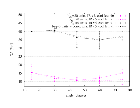
At collision energy, for the ultimate value of 0.3 m the minimum DA without any magnet imperfections is above 54, with minimum values at . When the dipole field imperfections of Table 1 are included in the simulations, the DA drastically drops with a minimum DA value of less than 10, as shown in Fig. 5. This is mainly due to the geometric aberrations induced by the 20 units of as shown by the grey dots in Fig. 5, where the value is set to 0. Moreover, the main sextupole strengths required to correct the chromatic aberrations induced by this are a factor 4 out of the reach of present technology. In order to ensure that the arcs have a small impact on the DA at collision (which is already greatly reduced by triplet imperfections Romanfcc and beam-beam) it is important to fully correct the . Furthermore, given the maximum integrated strength reachable by the spool piece correctors, the maximum amount of we can correct is 6 units (as discussed in previous section). The black dots in Fig. 5 show the perfect compensation of the chromatic and geometric aberrations due to 3 units of at collision. The average of each of the 8 arcs is corrected by the 12 spool pieces attached to each of the main dipoles. About 54 of the maximum strength of the spool pieces is used to correct the 3 units of . A maximum value of 3 units is assigned as target value for , which (according to the magnet group) seems to be feasible if up to 7 units of are allowed at injection Eziofcc . The different optics versions considered does not change significantly the DA at collision, as shown by comparing the pink dots and squares in Fig. 5.
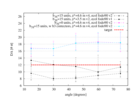
IV.2 Injection
At injection, without dipole imperfections the DA is above 80 for each angle explored. As far as the main dipole field imperfections are considered in the tracking simulations the minimum DA reduces to 14, as shown by the blue dots and squares in Fig. 6.
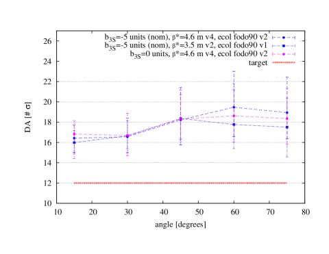
In these simulations, the geometric aberrations induced by the sextupole component of the dipole field are not corrected, while the chromatic aberrations, induced by the harmonics of the dipoles, are corrected using the main sextupoles of the arcs. The minimum DA is above the target value of 12 (safety margin adopted for the LHC design). Moreover, by comparing the blue dots and squares in Fig. 6 with the pink dots, where the systematic harmonics is set to 0 on purpose, the geometric aberrations generated by the 5 units of are well compensated by the phase advance of the arc cell. Moreover, as far as the systematic b3 component of the main dipole field errors stays at 5 units and the variation of the arc cell phase advance is around 1∘, the impact on the DA is negligible as shown by comparing blue dots with blue squares in Fig.6.
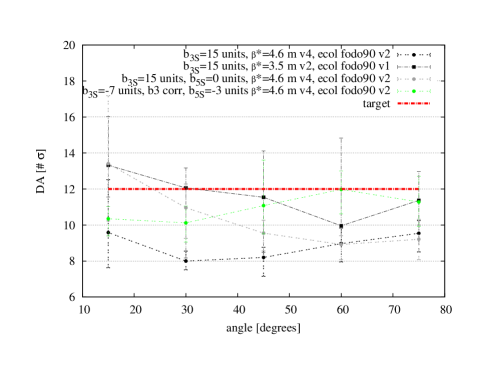
The black dots and squares in Fig. 7 represent DA computed with set to 15 units
on purpose, in order to see visible effects on DA. In both cases the minimum DA is below the target value of
12 (i.e. 8). Not only the geometric aberrations
generated by the are no more perfectly compensated by the arc cell phase advance, but the
main sextupole integrated strengths, required to correct the chromatic aberrations, run at values well
above the reach of present technology. Therefore, if the dipole field quality degrades due to persistent
current at injection energy (up to 15 units of ), a local correction scheme is needed also at injection,
namely spool pieces correctors attached to the main dipole, like in the LHC. Moreover, 1∘ difference
in the phase advance of the arc cell and the different phases between the arcs start producing significant effects
on DA ( 3 on the average DA at 15∘), as shown by the black dots and squares in Fig. 7.
The light blue dots in Fig. 7 show that the 15 units are fully corrected using spool
pieces correctors placed at each dipole of the arcs, correcting each the average of the 8 arcs.
Furthermore, the correctors strength effectively used for the correction is of the maximum
integrated strength that could be reached by present technology Eziofcc , leaving a lot of margin for
correction.
Finally, the impact on DA of 1 unit of can be seen by comparing the black dots with the grey dots in Fig. 8, where its value is artificially set to 0. This unit of reduces the average DA of 3 at 15∘, a similar impact is given by the 1∘ difference in the horizontal phase advance in the long arc cell(as shown by comparing the black dots and squares in Fig. 8). Moreover, with the correction of up to 15 units of the minimum DA is already above the target of 12. If the b5 component turns out to be 3 times bigger than the value given in Table 1, its impact on DA is not negligible anymore, as shown by the green dots in Fig. 8 and requires correction. In conclusion, if the systematic b5 component of the main dipoles errors stays strictly below 3 units, decapole correctors are not required for the present optics design.
V Detuning and Tunes spread
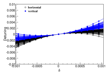
Multipoles can drive tune shift for particles with energy or amplitude offset. The control of the fractional tunes is correlated to the dynamic aperture. In the LHC, the width of the stability island corresponds to , i.e. for an induced tune shift of the order of or bigger than 10-2 a visible reduction of DA is expected. Detuning with amplitude and with momentum are faster and useful tools to complement DA calculations.
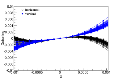
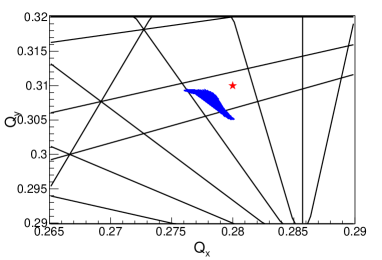
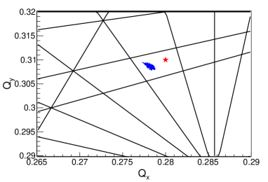
In Fig. 9 detuning with amplitude and momentum are shown in presence of the multipole field errors reported in Table 1, with the only difference that the systematic component of b3 has been set to the target value of 7 (current target value) and corrected with the spool pieces. The chosen working point (the red star in Fig. 9) is well away from resonances of order 5. The chromatic detuning is 6 for a maximum and the detuning of particles with amplitude from 1 to 7 (collimator settings proposed for FCC-hh FiasIpac16 ) is 5. The b4 and b5 multipoles errors are expected to impact the second and third order chromaticity SSC , respectively.


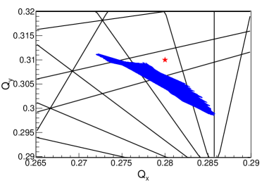

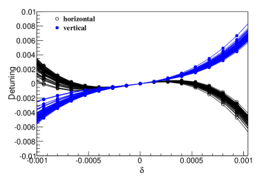
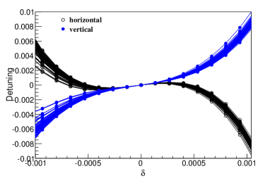
Figures 10 and 11 show the effect of the systematic component of b5 on the detuning with amplitude and with momentum, for different values of . Comparing these tune shifts with the DA simulations, shown in Fig. 8, we see that a tune shift of 0.910-3 at gives visible effects on DA, as well as a detuning with amplitude of 10-2, thus they should be avoided. Therefore, a tolerance on the maximum b5 component of the field can be fixed to 2 units. Finally, the other components of the dipole field errors reported in Table 1 generate all together a tune spread well below the value 10-2, so they have a minor impact on DA.
VI Discussion
In this section further qualitatively considerations are given about the injection energy, about feed-down effect and about the impact of dipole type on DA simulations.
VI.1 Injection Energy
As far as DA is concerned, the present estimate of the field errors reported in Table 1 and also the new target value for the systematic component of b3 (7 units) at injection guarantee that DA is above the target of 12. Considering that the ratio of DA at two different energies is equal to the ratio of the , the lower limit for injection energy, as far as DA is concerned and using the present field quality table, is set to 2.6 TeV. In order to reach the 1.5 TeV proposed in injfcc tighter tolerances on the random and uncertainty components of the main dipoles imperfections will be required to ensure the DA is above the 12 target value. Alternatively, a target for DA closer to the collimation settings limit (7 ) should be considered.
VI.2 Feed-down effect
All tracking simulations showed in this paper do not take into account mis-alignment of the magnetic elements. This is expected to change the value of the multipoles shown in Table 1 due to feed-down effects of higher order multipoles on the multipoles of lower order. Following Ref. Steph the expected feed-down of b3 on b2 and of b5 on b4 due to position errors of main dipoles and spool-piece can be calculated analytically. Considering the same alignment position errors reported in Table 8 of Ref. Steph one gets for the systematic component b:
| (3) |
which corresponds to values between 0.099 and 0.211, taking b equal to 7 or 15 units, respectively. For the random component of b2 one gets:
| (4) |
which gives values between 0.46 and 0.98, taking b equal to 7 or 15 units, respectively. In the case of 15 units the part of b2 due to feed-down becomes bigger than the estimated error due to the main dipole (0.481 units for both the bU and the bR component). These values should be added to the b2 of the main dipoles and will contribute to the -beating, which impacts the mechanical aperture of the machine. Moreover, main quadrupole, main sextupole and straight section field errors and mis-alignment will also contribute to the -beating and further reduce tolerances on acceptable total b2 and a2, and as a consequence of b3, coming from the main dipoles.
VI.3 Dipole type
In all the simulations results presented here curved dipole (SBEND type) have been considered, and the multipole field expansion is done around the magnetic center of the dipole, which coincide with the reference particle trajectory. Due to the properties of the Nb3Sn material, it has been proposed to build them straight (RBEND type). This implies that the reference particles does not travel always on the magnetic center of the element. The maximum beam excursion (the Sagitta ) due to the dipole field is about 2.5 mm. Therefore, assuming the multipole field expansion (of Eq. 1) is done always with respect to the magnetic axis. For a systematic offset equal to the Sagitta the maximum error on the b3 component of the field can be calculated using the same formula given for the feed-down harmonics (see Eq. (15) of Ref. Steph ):
| (7) |
This value is less than the random component of b3 reported in Table 1, which dominate the DA results as discussed in section IV. Moreover, considering that the multipole errors in the magnet are dominant at the magnet ends and almost zero at the longitudinal center of the magnet, the error on b3 is even less than the previous calculated value, if the beam is off-axis in the longitudinal center of the magnets. On the other hand the useful aperture of the beam will be reduced, therefore a balance should be found on the beam excursion along in the magnet. Finally, in any case the error would be systematic for each of the dipole, thus the error on b3 would be corrected by the spool pieces.
VII Conclusions
The arc magnet specifications are reported and discussed in connection with the magnet group feedback. As far as the first estimate of the main dipole field quality is considered, the dynamic aperture of the current optics design of the future hadron-hadron collider is above the target value of 12 at injection energy (3.3 TeV). The current main dipole imperfections would allow to reduce injection energy to a minimum value of 2.6 TeV, as far as dynamic aperture is considered as criterion. The possibility to correct up to 15 units of the systematic harmonics of the main dipoles is shown, leaving a lot of margin in the correctors strength at the injection energy of 3.3 TeV. A first tolerance on the b3 component is fixed to 7 units at injection but the feed-down effect on b2, which impact the -beating can further reduce this tolerance. No specification for the decapole correctors are given at this stage of the design and a tolerance to 2 units is fixed for the b5 component at injection, but first order feed-down of b5 on b4 can further reduce this tolerance. At collision energy the first estimate of the main dipole field quality strongly reduces DA (below 10). In particular, a new systematic value of the harmonics (3 units) has been specified as target. Moreover, a minimum spool pieces integrated strength of a factor 2 higher with respect to LHC is required. Further studies are needed to fully specify the main dipole field quality, in particular evaluate the impact on dynamic aperture of feed-down of the main harmonics due to mis-alignment errors.
ACKNOWLEDGMENT
The authors would like to thank Ezio Todesco for the tight collaboration in the definition of the magnet specifications and Stéphane Fartoukh for the useful comments and discussions.
References
-
(1)
L. Jin and F. Schmidt,
“Tune scan Studies for the LHC at Injection Energy”,
LHC Project Report 377,CERN, May,2000.
-
(2)
H. Grote, F. Schmidt and L.H.A. Leunissen,
“LHC Dynamic Aperture at Collision”,
LHC Project Note 197, August,1999.
-
(3)
A. Chancé et al.,
“Status of the beam optics of the future hadron-hadron collider FCC-hh”,
IPAC’16, 7th International Particle Accelerator Conference, 8 - 13 May 2016, Busan, Korea,2016.
http://accelconf.web.cern.ch/AccelConf/ipac2016/papers/tupmw020.pdf
-
(4)
R. Martin, R. Tomás and B. Dalena,
“Interaction Region for a 100 TeV Proton-Proton Collider”,
IPAC’15, 6th International Particle Accelerator Conference, 3 - 8 May 2015, Richmond, VA, USA.
http://accelconf.web.cern.ch/AccelConf/IPAC2015/papers/tupty001.pdf
- (5) A. S. Langner et al., “Developments on IR baseline design”, presented at the FCC week 2016, Rome, Italy, April 2016, unpublished.
-
(6)
W. Bartmann et al.,
“Beam transfer to the FCC-hh collider from a 3.3 TeV booster in the LHC tunnel”
IPAC’15, 6th International Particle Accelerator Conference, 3 - 8 May 2015, Richmond, VA, USA.
https://jacowfs.jlab.org/conf/y15/ipac15/prepress/THPF089.PDF
-
(7)
W. Bartmann et al.,
“FCC-hh dump concepts”,
presented at the FCC week 2016, Rome, Italy, April 2016, unpublished.
https://indico.cern.ch/event/438866/contributions/1085000/attachments/1256830/1855704/FCCweek_dumpsystems_11April16.pdf
-
(8)
M. Fiascaris et al.,
“First design of a proton collimation system for 50 TeV FCC-hh”,
IPAC’16, 7th International Particle Accelerator Conference, 8 - 13 May 2016, Busan, Korea.
http://accelconf.web.cern.ch/AccelConf/ipac2016/papers/wepmw006.pdf
-
(9)
A. Chancé et al.,
“First results for a FCC-hh ring optics design”,
Tech. Rep. CERN-ACC-2015-0035, CERN, Apr 2015.
-
(10)
B. Dalena et al.,
“First Considerations on Beam Optics and Lattice Design for the Future Hadron-Hadron Collider FCC-hh”,
IPAC’15, 6th International Particle Accelerator Conference, 3 - 8 May 2015, Richmond, VA, USA.
http://accelconf.web.cern.ch/AccelConf/IPAC2015/papers/webb2.pdf
-
(11)
E. Todesco et al.,
“Field quality, correctors and filling factor in the arcs”,
presented at the FCC WEEK 2016,
Rome, Italy, April 2016, unpublished.
-
(12)
O. Bruning et al.,
LHC Design Report, Vol. I, Chapter 4, 2004.
-
(13)
R. Wolf,
Field Error Naming Conventions for LHC magnets, Engineering Specification LHC-M-ES-0001, Geneva, CERN, Oct, 2001.
-
(14)
S. Fartoukh and O. Bruning, “Field Quality Specification for the LHC Main Dipole Magnets”,
LHC Project Report 501, October 2001.
-
(15)
C. Lorin et al.,
“FCC Main Quadrupoles”,
presented at the FCC WEEK 2016,
Rome, Italy, April 2016, unpublished.
https://indico.cern.ch/event/438866/contributions/1084942/attachments/1257882/1863267/cl_et_FCCMQ_2ndFCCweek_apr2016.pdf
-
(16)
D. Boutin et al.,
“Residual Orbit Correction Studies for the FCC-hh”,
presented at the 7th Int. Particle Accelerator Conf. (IPAC’16),
Busan, Korea, May 2016.
-
(17)
R. Martin,
“ reach studies”,
presented at the FCC WEEK 2016,
Rome, Italy, April 2016, unpublished.
-
(18)
Superconductive Super Collider Conceptual Design Report,
SSC-SR-2020 (1986).
-
(19)
L. Stoel et al.,
“High energy booster options for a future circular collider at CERN”,
IPAC’16, 7th International Particle Accelerator Conference, 8 - 13 May 2016, Busan, Korea.
http://accelconf.web.cern.ch/AccelConf/ipac2016/papers/mopoy007.pdf