Robust spin transfer torque in antiferromagnetic tunnel junctions
Abstract
We theoretically study the current-induced spin torque in antiferromagnetic tunnel junctions, composed of two semi-infinite antiferromagnetic layers separated by a tunnel barrier, in both clean and disordered regimes. We find that the torque enabling the electrical manipulation of the Néel antiferromagnetic order parameter is out of plane , while the torque competing with the antiferromagnetic exchange is in-plane . Here, and are the Néel order parameter direction of the reference and free layers, respectively. Their bias dependence shows similar behavior as in ferromagnetic tunnel junctions, the in-plane torque being mostly linear in bias while the out-of-plane torque is quadratic. Most importantly, we find that the spin transfer torque in antiferromagnetic tunnel junctions is much more robust against disorder than in antiferromagnetic metallic spin-valves due to the tunneling nature of spin transport.
I Introduction
Intensive research has been achieved in the field of spin transfer torque Slonczewski ; Berger ; Ralph_MMM2008 in ferromagnetic materials in the last two decades. Spin torque consists of the transfer of spin angular momentum from a spin-polarized flow of conduction electrons to the local magnetic moments of a ferromagnet. This spin transfer promotes magnetic excitations resulting in magnetization switching sun1999 ; katine2000 ; Chiba_prl2004 or self-sustained precessional motion Kiselev_Nature2003 ; Rippard_prl2004 . The typical device on which spin torque switching is commonly achieved is composed of two ferromagnets separated by a spacer that can be either metallic or insulating. The former is henceforth referred to as a metallic spin-valve, while the latter is called a (ferro)magnetic tunnel junction (F-MTJ). In both devices, the spin torque is dominated by an antidamping component of the form , where is the magnetization direction of the reference layer while is the magnetization direction of the free layer. In both cases, the torque is an interfacial process arising from the destructive interference between incoming electron spins with different incidences Stiles_prb2002 ; manchon2008 . In the case of F-MTJs, a field-like torque of the form also emerges that can be as large as 10 to 30% of the in-plane torque theodonis_prl2006 ; Xiao_prb2008 ; manchon2008 ; wil ; Heiliger_prl2008 , as confirmed experimentally Sankey_Nature_phys2008 ; Kubota_Nature_phys2008 ; Oh_Nature_phy_2009 . The bias dependence of these two torque components can be tuned by engineering the junction structural asymmetry kioussis ; manchon2010 ; wil or in the presence of interfacial electron-magnon scattering magnon .
A few years ago, the presence of spin transfer torque in metallic antiferromagnetic spin-valves has been predicted theoretically Nunez_prb2006 . The authors considered a structure composed of two antiferromagnetic layers spaced by a normal metal in analogy with the ferromagnetic spin-valve. Experimentally, the search for current induced torque in antiferromagnetic layers has been carried out by analyzing the alteration that occurs at the level of the exchange bias between ferromagnetic and antiferromagnetic layers in a conventional ferromagnetic spin-valveTsoi_prl2007 ; Urazhdin_prl2007 . However, not much progress has been realized experimentally since then due to the significant difficulty of maintaining sizable torques in these structures, as well as controlling and detecting independently the Néel order parameter dynamics. As a matter of fact, it was recently shown hamed_prb2014 ; Duine2007 that even a small amount of disorder dramatically reduces the magnitude of the torque. Indeed, in order to preserve large current-driven torques in antiferromagnetic spin-valves, the staggered spin density built up in the reference antiferromagnetic layer has to be transported coherently to the free antiferromagnetic layer. Disorder breaks translational invariance and prevents the coherent transmission of this staggered spin density through the spin-valve.
A solution to this issue is to generate local torques, i.e. spin currents and densities that do not need to be transmitted from one part of the device to another. Several strategies have been proposed to date, such as the use of antiferromagnetic domain walls Hals_prl2011 ; Swaving2011 , or the exploitation of spin-orbit torques Zelezny_prl2014 . Another approach is to exploit spin-dependent tunneling transport (see Ref. Merodio_apl2014, ), which is much less sensitive to momentum scattering. Recently, tunneling anisotropic magnetoresistance has been reported in IrMn/MgO junctionsPark_Nature2011 ; Wang2013 , demonstrating the high quality that can be achieved in such systems. Antiferromagnetic spintronics presents tremendous potential for applications and is now gaining significant momentumJungwirth2016 .
In the present work, we investigate spin transfer torques in antiferromagnetic tunnel junctions (AF-MTJ). We study the voltage dependence of the spin torque components for a junction composed of symmetric antiferromagnetic electrodes. We finally explore the effect of the disorder on the torque, demonstrating that the torque in AF-MTJ is much more robust against imperfections that in antiferromagnetic metallic spin-valves hamed_prb2014 .
II Methodology
The system we consider consists in two semi-infinite antiferromagnetic electrodes spaced by an insulating barrier (see Fig. 1). The two-dimensional antiferromagnets are square lattices in G-type magnetic configuration, i.e. each magnetic moment is surrounded by nearest neighbor moments of opposite direction. This configuration is different from the ones reported in previous theoretical works (Refs. Nunez_prb2006, ; Merodio_apl2014, ) in which the authors consider L-type antiferromagnets composed of uncompensated layers with magnetic moments pointing in opposite directions. The width of the junction’s layers is atomic sites while the barrier extends over 3 monolayers. In order to compute the transport properties of this system, we exploit the non-equilibrium Green’s function formalism implemented on the tight-binding code KWANT groth_NewJPhys , a procedure described in detail in Ref. hamed_prb2014, . The tight-binding Hamiltonian reads
| (1) |
The indices refer to the 2-dimensional coordinates of the sites. is the on-site energy, is the hopping parameter between the sites and , restricted to nearest neighbors and is the exchange energy between the staggered local magnetic moment on site and the itinerant electron spin ( in the antiferromagnets and in the barrier). is the vector of spin Pauli matrices where denotes a 22 matrix in spin space, is the creation operator of an electron on site , such that , where refers to the spin projection along the quantization axis. Compared to the metallic spin-valve studied in Ref. hamed_prb2014, , the present system comprises a tunnel barrier defined by an onsite energy at zero bias, where is the onsite energy of the metallic electrodes at zero bias. The non-equilibrium regime is promoted by applying a voltage in the range [-0.9t,0.9t] across the junction. The chemical potentials of the two antiferromagnetic electrodes are given by and the tunnel barrier onsite energy then reads , being the barrier length.

The nonequilibrium properties are computed from the lesser Green’s function (see Ref. wimmer_thesis, ), being the scattering wave functions originating from lead , with a Fermi-Dirac distribution . In the present work, we calculate the spin torque components from the local spin density , which reads
| (2) |
The integration runs over the full energy bandwidth up to the chemical potential of the left and right electrodes. The local torque on a particular lattice site reads .
In antiferromagnets composed of collinear sublattices, two types of torques can be defined at the level of the diatomic unit cell: torques arising from uniform spin densities (i.e. when the spin density is equal on the two sublattices), and torques arising from staggered spin densities (i.e. when the spin density is opposite on the two sublattices). In our previous work hamed_prb2014 , we called these two types of torque ”rotating” and ”exchange torques”, respectively. In systems without translational invariance, such as spin-valves, both types of torques exist in principle and possess components in and out of the () plane, where and are the Néel order parmaters of the polarizer and analyzer, respectively. At this stage, we want to point out a mistake in the discussion of our previous work, Ref. hamed_prb2014, . We claimed that the rotating torque (stemming from uniform spin density) is responsible for the Néel order parameter switching, while the exchange torque (stemming from staggered spin density) competes with the antiferromagnetic exchange and is therefore ineffective. This claim is incorrect since external magnetic fields (and hence, uniform spin densities) are unable to manipulate the direction of Néel order parameters and only result in spin-flop of the antiferromagnet. This confusion arises from the assumption that antiferromagnetic dynamics somewhat ressembles ferromagnetic one, which is clearly untrue since precession about the antiferromagnetic exchange field is the driving force in antiferromagnets (see also discussion in Ref. Zelezny_prl2014, ). Therefore, only staggered spin densities (producing ”exchange” torques) are efficient in controlling Néel order parameter direction Jungwirth2016 ; Gomonay2014 .
III Results and discussions
III.1 Premises
Before discussing the theoretical results, it is instructive to consider the band structure of a prototypical G-type antiferromagnet. The tight-binding Hamiltonian, Eq. (1), can be rewritten in the space, where refer to the antiferromagnetically coupled sublattices. One obtains
| (3) | |||
| (4) |
which supports the following eigenstates
| (5) | |||
| (6) |
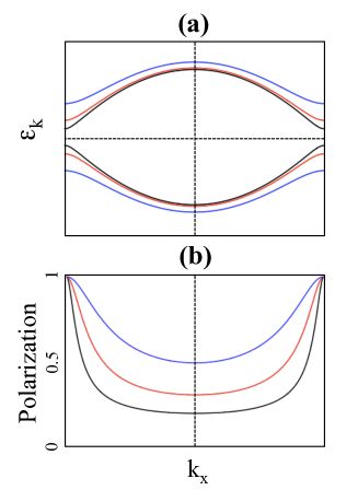
and . Here, we chose the Néel order parameter to lie along and , are spin Pauli matrices referring to the and subspaces, respectively. The band structure, Eq. (5), is plotted in Fig. 2(a) for different values of the exchange energy . One obtains the usual gapped electronic structure of antiferromagnets. By increasing the exchange, the band gap increases and the band width is slightly compressed.
Although both up and down spin are degenerate, one can define a local spin polarization on each sublattice. In the low band filling limit, , the density of state on sublattice ( corresponds to sublattice A and corresponds to sublattice B) is indeed
| (7) |
which produces a polarization
| (8) |
where is measured from the center of the gap. Therefore, the sublattice-resolved polarization is perfect () at the band edges () and decreases to a minimum at the extrema of the bands, as illustrated in Fig. 2(b). Since remains finite, the minimum polarization never vanishes. It is also remarkable that the polarization is essentially flat, i.e. energy independent, close to . This trend is opposite to that of ferromagnets, whose density of state polarization reads and decreases when the energy increases away from the bottom of the bands. These features will be essential to understand the robustness of spin torque against disorder in the tunnel barrier, as discussed further below.
III.2 Spin density profile
Let us now compute the spin torque components in antiferromagnetic tunnel junctions. In the following, we fix Néel order parameter direction of the left antiferromagnet along direction, while the one of the right antiferromagnet points along the direction, as illustrated in Fig. 1. To get better insight about the physics at stake, we will consider two band filling situations: (i) , when Fermi energy is located in the middle of the bottom band and (ii) , when Fermi energy is located in the middle of the top band (see Fig. 1). In the following, we take eV and the Fermi energy is defined from the bottom of the valence band.

Upon finite bias voltage, electrons originating from the left antiferromagnetic electrode acquire a staggered spin density along that is injected into the right electrode, as represented by the blue symbols in Fig. 3(a). In the right, downstream antiferromagnet the itinerant electron spins reorient along the local Néel order parameter, i.e. along direction [see green symbols in Fig. 3(a)]. During this reorientation, the spin density component transverse to the local Néel vector is transferred to the local magnetic moments of the right antiferromagnet. The two spin components transverse to the local Néel order parameter of the right layer are reported in Fig. 3(b,d) and (c,e) at different exchange energies and for eV and eV, respectively. For the sake of readability, we report the value of the spin densities normalized to their magnitude at the right interface (actual values of the torque are reported on Fig. 4).
The spin density displays a clear oscillatory decay [Fig. 3(b)], which resembles the behavior observed in F-MTJs (see e.g. Ref. manchon2008, ) but is in sharp contrast though with our previous calculations in metallic spin-valveshamed_prb2014 where no such decay is observed. The decay increases when increasing the Fermi energy to eV [Fig. 3(c)], and when decreasing the exchange energy . We attribute this decay to spin dephasing arising from destructive interference between incoming electrons. Indeed, tunneling involves interference between different bands below the Fermi level. Increasing the Fermi level from 1.1 eV [Fig. 3(b)] to 6.6 eV [Fig. 3(c)] increases the number of bands involved in the tunneling process and thereby enhances the spin dephasing. Furthermore, reducing the exchange widens the bandwidth (see Fig. 2), which also participates to the enhancement of the destructive interference by allowing more states to tunnel.
The component presents a markedly different behavior [Fig. 3(d)]. It also decays away from the interface, but does not present oscillations. As a matter of fact, while arises from the direct injection of the staggered spin density from the left to the right antiferromagnet, stems from the precession of about the local staggered field. This staggered precession results in a uniform component that presents the same decaying characteristics as . Moreover, in the case eV reaches a constant value away from the interface, while for eV, it completely vanishes within a few atomic planes [Fig. 3(e)]. The latter is also a consequence of strong spin dephasing.
III.3 Voltage dependence
We now turn our attention towards the bias-dependence of the spin transfer torque. From Fig. 3, one can anticipate that (which produces the out-of-plane torque, ) provides a dominant staggered density (corresponding to an ”exchange” torque in our denomination of Ref. hamed_prb2014, ), while (which produces the in-plane torque, ) provides a dominant uniform density (corresponding to a ”coherent” torque in our denomination of Ref. hamed_prb2014, ). As discussed above, only the former enables electrical manipulation of the Néel order parameter. To compute the effective torque acting on the layer, we define
| (9) | |||||
| (10) |
where the subscript () stands for out-of-plane (in-plane) torque component, and is the volume of the right antiferromagnet layer. The unit is given in , where is the hopping parameter in eV and is the lattice parameter (typically 0.4 nm). These torques are reported in Fig. 4(a,b), respectively, for eV as a function of the bias voltage.
The bias dependence of these two torques is very similar to what is usually observed in F-MTJs theodonis_prl2006 ; manchon2008 ; Xiao_prb2008 ; wil : the in-plane torque displays a bias dependence of the form , while the out-of-plane torque is mostly quadratic, . Of course, if one introduces asymmetries in the junction, additional linear dependence should appearwil ; manchon2010 ; kioussis . Remarkably, the magnitude of the torques reported in Fig. 4 is comparable to the one reported for F-MTJs (see, e.g. Ref. theodonis_prl2006, ). We conclude that in a clean AF-MTJ, the current-driven torque efficient to manipulate the Néel order parameter direction is an out-of-plane torque that depends on the bias voltage in a quadratic manner. Hence, if one does not break the symmetry of the system, the torque always acts in the same direction, insensitive to the bias polarity.
III.4 Effect of the disorder
The impact of spin-independent disorder on spin transport in antiferromagnets is a crucial issue. In general, depending on the growth conditions and techniques, the mean free path is limited by the grain size (i.e. from 5 to 15 nm), which has dramatic impact on spin transport in antiferromagnetshamed_prb2014 . To implement disorder in our system, we follow the same procedure as in Ref. hamed_prb2014, and introduce a random onsite potential such that , where is the disorder strength. At this stage, the computation becomes extremely demanding as both large disorder configurational average together with accurate energy integration are required. In order to ensure the good convergence of our calculation, the Fermi energy is taken at eV such that a large number of modes are present in the system, thereby increasing spin dephasing and improving numerical accuracy.
III.4.1 Disorder in the metallic leads

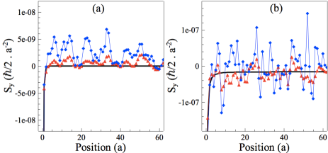
Let us first introduce disorder in the antiferromagnetic leads. Figs. 5 and 6 display the spatial profile of and , respectively, for different disorder strengths and exchange energies. The clean regime is also reported for comparison (solid lines in Figs. 5 and 6). Symbols represent the disordered regime with ranging from to eV. Since the spin density decreases dramatically within two monolayers from the interface (see Fig. 3), we focus on the impact of disorder on the oscillatory decay of the spin density in the bulk of the antiferromagnet. For weak disorder (red symbols) in Fig. 5(a) and (b), the oscillation of remains weakly affected, while increasing the disorder results in enhanced deviations (blue symbols). However, Fig. 5(a) and (b) show that disorder mostly affect the spin density in the bulk of the antiferromagnet, away from the interface. As a result, since the torque mostly occurs at the interface where the spatial decay is stronger, the overall torque magnitude remains only weakly affected by disorder. A similar conclusion can be drawn for , displayed in Fig. 6. Again the magnitude of is mostly affected by bulk disorder, while its value close to the interface remains robust. As a conclusion, the overall impact of disorder on spin torque is much less dramatic than in metallic spin-valve since in AF-MTJ the torque is mainly an interfacial effect.
III.4.2 Disorder in the tunnel barrier
The impact of disorder in the tunnel barrier on spin transport has been reported in the case of tunneling magnetoresistance in F-MTJs Tsymbol_CondMatt2003 . In these structures, the disorder inside the tunnel spacer is detrimental to spin transport properties since a local reduction of the barrier heigh or thickness enhances the tunneling current while reducing its spin polarization. In other words, the presence of disorder in the tunnel barrier introduces hot spots of weakly polarized current that dominate the magnetoresistance signal. Let us now consider the impact of disorder in the barrier on spin torque in F-MTJs. Fig. 7(a) shows the torkance - or torque efficiency -, defined as the torque normalized to the conductance, exerted on the right ferromagnetic layer. The torkance (proportional to the interfacial polarization) dramatically decreases in the presence of disorder, which is consistent with the behavior previously observed for the tunneling magnetoresistanceTsymbol_CondMatt2003 .
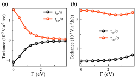
We now turn our attention towards the effect of disorder on the spin transfer torque in AF-MTJs, reported in Fig. 7(b) [the parameters are the same as in Fig. 7(a)]. Surprisingly, the torkance remains mostly unaffected by the disorder, in sharp contrast with F-MTJs. This illustrates the major difference between AF-MTJs and F-MTJs: since up and down spins are degenerate [see Fig. 2 and related discussion], the hot spots introduced by the disorder only results in an enhancement of the tunneling current without altering the sublattice polarization. As a consequence, the spin torque efficiency in AF-MTJs is much more robust against disorder than in F-MTJs.
IV Conclusion
In the present work we studied the spin transfer torque in AF-MTJs using a real-space tight-binding model. We have shown that, similarly to the case of F-MTJs, the antiferromagnetic torque is interfacial and possesses both in-plane and out-of-plane torques, the former being mostly linear in bias voltage while the latter is quadratic for a symmetric system. However, two main differences have been identified. First of all, since only staggered spin densities are efficient in manipulating Néel order parameter, the efficient torque is out-of-plane. Second, because up and down spins are degenerated in antiferromagnets, the torque efficiency in AF-MTJs is much more robust against disorder than in F-MTJs. This shows that AF-MTJs are solid candidates for the realization of spin transfer torque in antiferromagnets.
Acknowledgements.
A.M. acknowledges the financial support of the King Abdullah University of Science and Technology (KAUST) through the Office of Sponsored Research (OSR) [Grant Number OSR-2015-CRG4-2626].References
- (1) J. C. Slonczewski, J. Magn. Magn. Mater. 159, L1 (1996).
- (2) L. Berger, Phys. Rev. B 54, 9353 (1996).
- (3) D. C. Ralph and M. D. Stiles, J. Magn. Magn. Mater. 320, 1190 (2008).
- (4) J. Z. Sun, J. Magn. Magn. Mater. 202, 157 (1999); J.
- (5) J. A. Katine, F. J. Albert, R. A. Buhrman, E. B. Myers and D. C. Ralph, Phys. Rev. Lett. 84, 3149 (2000).
- (6) D. Chiba, Y. Sato, T. Kita, F. Matsukura and H. Ohno, Phys. Rev. Lett. 93, 216602 (2004); Y. Huai, F. Albert, P. Nguyen, M. Pakala, and T. Valet, Appl. Phys. Lett. 84, 3118 (2004); G. D. Fuchs et al., Appl. Phys. Lett. 85, 1205 (2004).
- (7) S.I. Kiselev, J.C. Sankey, I.N. Krivorotov, N.C. Emley, R.J. Schoelkopf, R.A. Buhrman, D.C. Ralph, Nature 425, 380 (2003).
- (8) W.H. Rippard, M.R. Pufall, S. Kaka, S.E. Russek, T.J. Silva, Phys. Rev. Lett. 92, 027201 (2004).
- (9) M. D. Stiles and A. Zangwill Phys. Rev. B, 66, 014407 (2002).
- (10) A. Manchon, N. Ryzhanova, N. Strelkov, A. Vedyayev, M. Chshiev and B. Dieny, J. Phys.: Condens. Matter 20, 145208 (2008); ibid 19, 165212 (2007).
- (11) I. Theodonis, N. Kioussis, A. Kalitsov, M. Chshiev, W.H. Butler, Phys. Rev. Lett. 97, 237205 (2006); A. Kalitsov, M. Chshiev, I. Theodonis, N. Kioussis, and W. H. Butler, Phys. Rev. B 79, 174416 (2009).
- (12) J. Xiao, G. E. W. Bauer, and A. Brataas, Phys. Rev. B. 77, 224419 (2008).
- (13) M. Wilczynski, J. Barnas, and R. Swirkowicz, Phys. Rev. B 77, 054434 (2008).
- (14) C. Heiliger and M. D. Stiles, Phys. Rev. Lett. 100, 186805 (2008).
- (15) J.C. Sankey, Y.-T. Cui, J.Z. Sun, J.C. Slonczewski, R.A. Buhrman, D.C. Ralph, Nat. Phys. 4, 67 (2008).
- (16) H. Kubota, A. Fukushima, K. Yakushiji, T. Nagahama, S. Yuasa, K. Ando, H. Maehara, Y. Nagamine, K. Tsunekawa, D.D. Djayaprawira, N. Watanabe, Y. Suzuki, Nat. Phys. 4, 37 (2008).
- (17) S-C. Oh, S-Y. Park, A. Manchon, M. Chshiev, J-H. Han, H-W. Lee, J-E. Lee, K-T. Nam, Y. Jo, Y-C. Kong, B. Dieny and K-J. Lee, Nature physics, 5, 898 (2009).
- (18) A. Manchon, S. Zhang, and K.-J. Lee, Phys. Rev. B 82, 174420 (2010).
- (19) Y.-H. Tang, N. Kioussis, A. Kalitsov, W. H. Butler, and R. Car, Phys. Rev. Lett. 103, 057206 (2009); Phys. Rev. B 81, 054437 (2010).
- (20) A. Manchon and S. Zhang, Phys. Rev. B 79, 174401 (2009).
- (21) A. S. Nunez, R. A. Duine, P. Haney, and A. H. MacDonald, Phys. Rev. B. 73, 214426 (2006).
- (22) Z. Wei, A. Sharma, A. S. Nunez, P. M. Haney, R. A. Duine, J. Bass, A. H. MacDonald, and M. Tsoi, Phys. Rev. Lett. 98 116603 (2007).
- (23) S. Urazhdin and N. Anthony, Phys. Rev. Lett. 99, 046602 (2007).
- (24) H. B. M. Saidaoui, A. Manchon, and X. Waintal, Phys. Rev. B 89 174430 (2014).
- (25) R. A. Duine, P. M. Haney, A. S. Núñez, and A. H. MacDonald, Phys. Rev. B 75, 014433 (2007).
- (26) K. M. D. Hals, Y. Tserkovnyak, and A. Brataas, Phy. Rev. Lett, 106, 107206 (2011); E. G. Tveten, A. Qaiumzadeh, and A. Brataas, Phys. Rev. Lett, 112, 147204 (2013).
- (27) A. C. Swaving and R. A. Duine, Phys. Rev. B 83, 054428 (2011); J. Phys.: Condens. Matter 24, 024223 (2012).
- (28) J. Zelezny, H. Gao, K. Vyborny, J. Zemen, J. Majek, A. Manchon, J. Wunderlich, J. Sinova, and T. Jungwirth, Phys. Rev. Lett, 113, 157201 (2014); Wadley et al., Science 351, 587 (2016).
- (29) P. Merodio, A. Kalitsov, H. Bea, V. Baltz, and M. Chshiev, App. Phy. Lett. 105, 122403 (2014).
- (30) B. G. Park, J. Wunderlich, X. Marti, V. Holy, Y. Kurosaki, M. Yamada, H. Yamamoto, A. Nishide, J. Hayakawa, H. Takahashi, A. B. Shick, and T. Jungwirth, Nature Materials 10, 347 (2011); X. Martí, B. G. Park, J. Wunderlich, H. Reichlová, Y. Kurosaki, M. Yamada, H. Yamamoto, A. Nishide, J. Hayakawa, H. Takahashi, and T. Jungwirth, Phys. Rev. Lett. 108, 017201 (2012).
- (31) Y. Y. Wang, C. Song, B. Cui, G. Y. Wang, F. Zeng and F. Pan, SPIN 3, 1350005 (2013).
- (32) T. Jungwirth, X. Martí, P. Wadley and J. Wunderlich, Nature Nanotechnology 11, 231 (2016).
- (33) E. V. Gomonay, and V. M. Loktev, Low Temperature Physics 40, 17 (2014).
- (34) C. W. Groth, M. Wimmer, A. R. Akhmerov and X. Waintal, New Journal of Physics, 16, 063065 (2014).
- (35) M. Wimmer (2009). Quantum transport in nanostructures: From computational concepts to spintronics in graphene and magnetic tunnel junctions. Book series of the Department of Physics at the University of Regensburg 5, PhD, University of Regensburg.
- (36) E. Y. Tsymbal, O. N. Mryasov, P. R. LeClair, J. Phys.: Condens. Matter 15, R109 (2003).