Design of a quasi-2D photonic crystal optomechanical cavity with tunable, large -coupling
Abstract
We present the optical and mechanical design of a mechanically compliant quasi-two-dimensional photonic crystal cavity formed from thin-film silicon in which a pair of linear nanoscale slots are used to create two coupled high- optical resonances. The optical cavity supermodes, whose frequencies are designed to lie in the nm wavelength band, are shown to interact strongly with mechanical resonances of the structure whose frequencies range from a few MHz to a few GHz. Depending upon the symmetry of the mechanical modes and the symmetry of the slot sizes, we show that the optomechanical coupling between the optical supermodes can be either linear or quadratic in the mechanical displacement amplitude. Tuning of the nanoscale slot size is also shown to adjust the magnitude and sign of the cavity supermode splitting , enabling near-resonant motional scattering between the two optical supermodes and greatly enhancing the -coupling strength. Specifically, for the fundamental flexural mode of the central nanobeam of the structure at MHz the per-phonon linear cross-mode coupling rate is calculated to be MHz, corresponding to a per-phonon -coupling rate of kHz for a mode splitting GHz which is greater than the radiation-limited supermode linewidths.
I Introduction
Multimode optomechanical systems consisting of three or more optical and mechanical modes have recently received growing interest within the field of cavity optomechanics Aspelmeyer et al. (2014). One of the main original motivations for multimoded systems was the prospect of realizing a quantum non-demolition (QND) measurements of mechanical energy or phonon number using position-squared optomechanical coupling arising from the novel dispersion of a multimode optical system Jayich et al. (2008); Thompson et al. (2008); Ludwig et al. (2012). While QND measurements turn out to be very challenging in such a set-up Ludwig et al. (2012); Miao et al. (2009a), multimode optomechanical systems are promising for studying a variety of other interesting phenomena, such as three-mode parametric instability Braginsky et al. (2001, 2002); Braginsky and Vyatchanin (2002), multimode optomechanically induced transparency Ojanen and Børkje (2014); Fan et al. (2015), synchronization of mechanical oscillators Heinrich et al. (2011); Zhang et al. (2012); Bagheri et al. (2013); Matheny et al. (2014) and the generation of sub-Poissonian statistics Xu and Li (2013); Flayac et al. (2015); Lemonde et al. (2014); Lörch and Hammerer (2015). Multimode optomechanical systems may also find application in displacement sensing Kippenberg et al. (2005); Krause et al. (2012) and optical information processing Schmidt et al. (2012), where they can be used as optical filters Winger et al. (2011), switches or delay lines Stannigel et al. (2012); Chang et al. (2011); Safavi-Naeini et al. (2011); Weis et al. (2010). Given the strong interest and opportunity in multimode cavity optomechanics, a number of new experimental platforms have been developed. These include membrane-in-the-middle setups Thompson et al. (2008); Sankey et al. (2010); Lee et al. (2015); Chen et al. (2015), nanofabricated chip-scale resonators Grudinin et al. (2010); Fan et al. (2015); Doolin et al. (2014); Chen et al. (2015), hybrid multimode microwave circuits Massel et al. (2012), and gravitational wave detectors Evans et al. (2015).
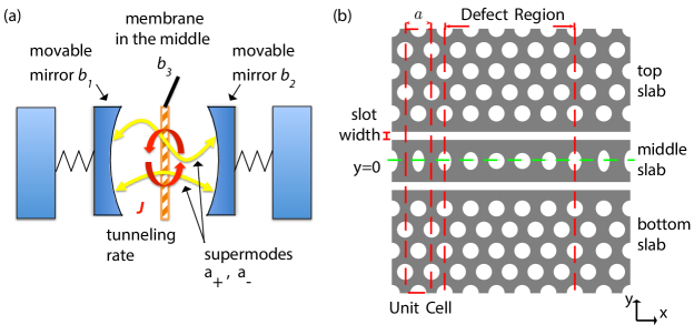
In a recent experimental work, we realized a silicon photonic crystal optomechanical cavity capable of very large position-squared optomechanical coupling Paraïso et al. (2015). Here, we present details of the cavity design and explore the range of possible optomechanical interactions in such a device. As shown schematically in Fig. 1 the structure consists of a double-waveguide photonic crystal cavity in which two individual waveguide cavity modes are coupled by photon tunneling through a mechanically compliant element. The double-waveguide cavity localizes two optical resonances at telecommunication wavelengths 1550 nm with high quality factors . The optical modes couple efficiently to mechanical modes with frequencies ranging from MHz up to GHz. We propose a tuning scheme based on electrostatic actuation Winger et al. (2011), which allows for control of the optical tunneling rate between the two slotted waveguide modes as well as the supermode frequencies. This provides a direct dynamical control over the linear and quadratic optomechanical coupling strengths.
The paper is organized as follows. We start in Sec. II with a brief introduction of the theory of multimode optomechanics. We consider a generic Hamiltonian describing a system of two optical modes and a series of mechanical modes. Coupling between the optical modes occurs via mechanically independent photon tunneling, and via absorption or emission of mechanical phonons. By considering specific symmetries of the optical and mechanical modes we show how different orders of coupling in mechancial amplitude can occur. In Sec. III we detail the design of the specific double-slotted photonic crystal cavity of interest to our work. We show that by controlling the widths of the waveguide slots of the structure it is possible to adjust the photon tunneling rate of the optical modes, and to even completely suppress this tunneling. In Sec. IV we analyze the mechanical resonances of the photonic crystal cavity and identify several mechanical modes with frequencies ranging from MHz to GHz that have the appropriate symmetry for realizing large optomechanical coupling. Finally, in Sec. V we employ a perturbation theory to calculate the strength of the linear self-mode, linear cross-mode, and position-squared coupling a number of the different mechanical resonances of the photonic crystal structure.
II Multimode Hamiltonian
We consider a multimode cavity optomechanical system consisting of two spatially separated optical modes of frequencies and independent mechanical modes of frequencies . The individual optical cavity modes are coupled to each other through photon tunneling at a rate . Conceptually, our structure can be viewed as an on-chip generalization of the membrane-in-middle setups Thompson et al. (2008); Ludwig et al. (2012) in a chip-scale architecture, as it is schematically represented in Fig. 1. The corresponding Hamiltonian can be written as,
| (1) | ||||
where are the coupling strengths between the optical modes , and the mechanical mode . In the particular case of symmetric optical cavities, and are degenerate with . Since the individual optical modes are spatially separated, we can to a good approximation neglect the terms proportional to with and therefore write simply as . By introducing the supermode basis , we can diagonalize which yields for the total Hamiltonian,
| (2) | ||||
where the frequency difference between the supermodes at zero mechanical displacement is . The first term inside the brackets of Eq. (2) describes the linear self-mode optomechanical coupling of the supermodes to the mechanical mode of interest. The last term describes the linear cross-mode optomechanical coupling, i.e. the coupling between the supermodes mediated by the mechanical vibrations. In the basis we have for the linear self-mode optomechanical coupling to mechanical mode ,
| (3) |
and the linear cross-mode optomechanical coupling,
| (4) |
Following the approach of Ref. Ludwig et al. (2012), we further diagonalize the full Hamiltonian assuming a quasi-static approximation for the mechanical motion. The resulting eigenfrequencies of the supermodes are,
| (5) |
where the mechanical displacements are regarded as a quasi-static variables. Focusing on a single mechanical mode and Taylor expanding the optical supermode frequencies as a function of small displacement around equilibrium position yields,
| (6) |
where
| (7) |
and
| (8) |
Here is the linear (self-mode) coupling coefficient and is the quadratic coupling coefficient of the supermode to the mechanical mode . In what follows we will be primarily interested in the linear and quadratic coupling coefficients around the symmetric equilibrium position , where the linear coupling is trivially and the quadratic coupling can be related to the linear cross-mode coupling of the supermodes,
| (9) |
We return to the more general result for in Sec. V.4.
From the above expressions, mechanical modes such that will have vanishing linear self-mode couplings to the supermodes, while mechanical modes such that will have vanishing linear cross-mode coupling strength. All intermediate cases such as can of course occur in general. In the following, we introduce a photonic crystal optomechanical resonator supporting multiple mechanical modes of different symmetries and with optimized overlap with the optical modes. We show that by engineering the bandstructure and defect of the photonic crystal the splitting between the optical supermodes can be tuned to arbitrarily small values, which greatly enhances the -coupling strength.
III Multimode Photonic Crystal Optomechanical Cavity
III.1 Bandstructure properties
In this paper, we design our structure assuming a silicon thin film device layer of thickness nm, Young’s modulus GPa, mass density kgm3 and refractive index . Our initial geometry is a quasi-two-dimensional (quasi-2D) periodic photonic crystal membrane patterned with a triangular lattice of holes (lattice constant nm, circular hole radius ) This structure has an in-plane photonic bandgap (a pseudo-bandgap) for guided slab modes of predominantly TE polarization (electric field polarized in the plane of the slab) around a free-space wavelength of nm. Referring to Fig. 1(b), addition of the slots breaks the translational periodicity in the transverse direction (-direction), leaving a periodic structure of lattice constant in the longitudinal () direction. Introducing two air slots of width nm into the photonic crystal membrane results in a pair of optical waveguides with guided modes localized to each of the individual air slots due to the pseudo-bandgap. As shown in Fig. 1(b), this splits the triangular lattice into two outer slabs and a central beam.
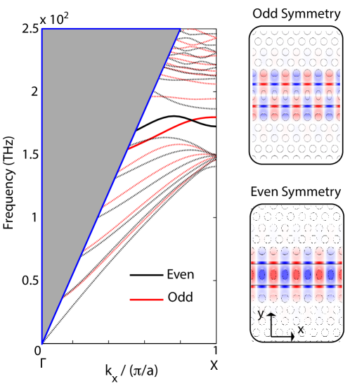
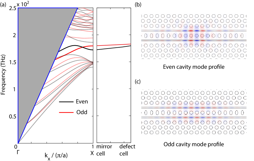
The optical bandstructure of the guided modes of the double-slotted waveguide structure with a central beam consisting of a single row of air holes is plotted in Fig. 2. The optical bandstructures here and in what follows are computed using the MIT Photonic Bands package Johnson and Joannopoulos (2001). To simplify the bandstructure we only plot the optical bands with TE-like polarization (more accurately we plot those modes with even vector symmetry about the mid-plane of the photonic crystal thin-film slab). In addition to the symmetry about the mid-plane of the silicon thin-film slab – corresponding to the mirror operator – the double-slotted waveguide structure also has a symmetry plane about the plane as indicated by the green line in Fig. 1(b). The mirror operator corresponding to this symmetry we label , and the modes of the double-slotted photonic crystal waveguide can be categorized by their even and odd parity under . Here we use the labeling convention that the waveguide supermode with even electric field profile is called the “even” mode, while the waveguide supermode with odd electric field profile is termed the “odd” mode (note that classifying the modes by their vector symmetry would swap the mode labels). The even and odd waveguide bands are shown as solid black and red lines in Fig. 2. The back and red dashed curves correspond to the unguided (in the transverse -direction) modes of the triangular photonic crystal slabs surrounding each air slot. The shaded grey region corresponds to the region above the light cone of the air cladding surrounding the silicon slab, in which a continuum of radiation modes freely propagate out of the plane of the slab ( direction). The insets to the right of the bandstructure plot in Fig. 2 show the field profiles of the even and odd waveguide modes at the edge of the first Brillouin zone (-point).
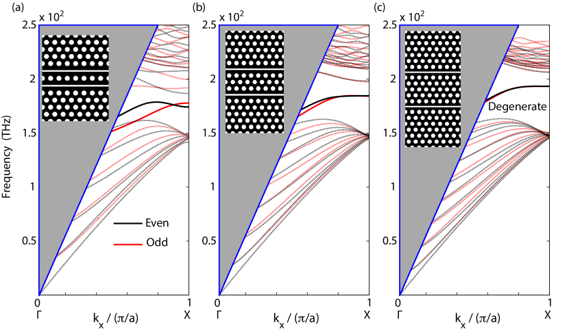
In the hopes of achieving large -coupling strengths, our focus will be to design photonic crystal cavity modes with minimal optical splitting (see Eq. (9)). An obvious way to minimize the optical coupling between the slot waveguide modes would be to increase the separation between the slots. This decreases the photon tunneling rate , and hence decreases the frequency splitting between the waveguide modes. For instance, we show in Fig. 3 that the frequency splitting between the odd and even waveguide modes at the -point can be decreased from THz in the case of waveguide slots separated by a single row of holes, all the way down to GHz for waveguide slots separated by five rows of holes. In the latter case the bands become nearly degenerate over a significant fraction of the Brillouin zone, whereas in the more strongly-coupled case of a single row of holes the even and odd waveguide bands have different slopes and even cross near the -point. The mode profiles of the even and odd waveguide supermodes are plotted in Fig. 2 for a separation between slots of a single row of holes, with the odd waveguide modes having a node in the center of the central beam, and thus, more of their energy in the air slots. As described below, for a cavity based upon the coupled waveguides, this feature allows one to control the relative mode frequencies of the even and odd cavity supermodes by changing the size of the air slot gaps in the structure.
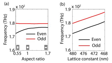
In addition to slot width and slot separation, the fact that the even waveguide modes have more of their energy in the central beam may also be exploited to tailor the relative frequencies of the waveguide supermodes. We consider a middle slab consisting of a single row of holes (nanobeam) and analyze the impact of the ellipticity and lattice constant on the frequency of the waveguide modes. We parametrize the ellipticity of the holes by the aspect ratio , where () are the semi-axis of the ellipse in () direction, so that corresponds to circular holes. Further, by setting and where is circular radius of the unperturbed cells, we keep the air filling fraction invariant between the elliptical holes and the circular holes. Fig. 4(a) shows the frequency shift of the bands at the -point due to the variation in the aspect ratio of the holes in nanobeam. Only the even band is influenced while the odd band does not shift. For completeness we show in Fig. 4(b) the scaling of the even and odd waveguide modes at the -point versus a scaling of the in-plane lattice constant (i.e., slab thickness constant). As one might expect, the splitting between the waveguide supermodes of different parity are relatively unaffected by the lattice scaling.
III.2 Optical cavity
To form an optical cavity from the coupled waveguide system described above we need to find a way of closing the ends of the waveguides. To this end, we introduce a “defect” in the waveguide structure by modifying the geometrical parameters of the waveguide along its propagation () axis. This defect region of the waveguide is then embedded between two “mirror” sections of the waveguide as depicted in Fig. 1. Localized cavity modes result for a waveguide modification that pushes the -point waveguide supermode frequencies in the defect unit cells inside the pseudo-bandgap of the unperturbed mirror unit cells Eichenfield et al. (2009a); Chan et al. (2009).
Here the cavity is designed by combining the two defects shown in Fig. 4. The lattice constant is decreased from nm to nm quadratically over cells at the center of the structure. Simultaneously with the scaling of the lattice constant, the aspect ratio of the air holes in the central nanobeam are increased from to circular holes with while keeping a constant air filling fraction. Fig. 5(a) shows the modification of the waveguide mode frequencies from the unperturbed mirror cells to the central defect cell. The change in the lattice constant pushes the mode frequencies inside the bandgap and the change of hole ellipticity reduces the frequency splitting between the even and odd supermodes. We simulated the full cavity structure using the COMSOL Multiphysics com finite-element-method (FEM) solver. The length of the entire cavity consists of a total of waveguide unit cells along the -axis, with central defect unit cells. Each of the outer photonic crystal slabs have rows of air holes in the transverse -direction. Fig. 5(b) and Fig. 5(c) show the field profiles for the odd and the even cavity supermodes, respectively. With the given parameters, the odd mode has a simulated free-space wavelength of nm and a radiation-limited optical -factor of . The even mode has a free-space wavelength of nm and a substantially lower radiation-limited -factor of . This asymmetry in -factor results from both the larger coupling to even waveguide modes away from the -point in the mirror section, a result of the non-monotonic dispersion of the even band, and the reduced vertical radiation loss for a mode of odd in-plane symmetry Srinivasan and Painter (2002).
III.3 Dependence of the cavity supermode frequency splitting on the slot size
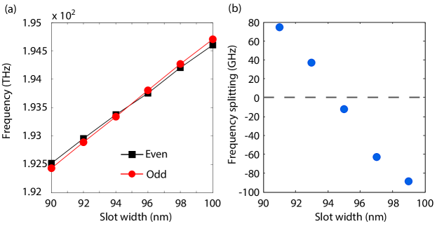
Since the optical modes of interest are mostly localized in the air slots, their frequencies are strongly impacted by the width of the air slots . Increasing causes the effective refractive index of the optical waveguide modes to decreases, yielding a blue shift of the resulting optical cavity frequencies. FEM simulations of the waveguide supermodes of the double-slotted photonic crystal structure for slot widths ranging from nm to nm are plotted in Fig. 6 (a). The frequencies increase approximately linearly with with slightly different slopes, resulting in a crossing of the cavity supermodes at nm. This crossing is made more apparent in Fig. 6(b), where the relative splitting between the even () and odd () supermode frequencies, , is plotted.
As we see, by solely modifying the slots width, it is possible to change the splitting between the cavity supermodes () from positive to negative. This is again explained by looking at the even and odd field profiles shown in Fig. 5(b) and 5(c). Since the odd mode has a node in the middle of the central nanobeam, its effective refractive index is more sensitive to a change in the air region than the even cavity supermode. Therefore, for an equal change of the slot widths the frequency of the odd cavity supermode shifts more than the frequency of the even cavity supermode. It is also worth noting that the crossing of the cavity supermodes is only possible because the odd and even waveguide bands cross (see Fig. 5(a)), with the even waveguide band having a higher frequency than the odd waveguide band slightly away from the -point.
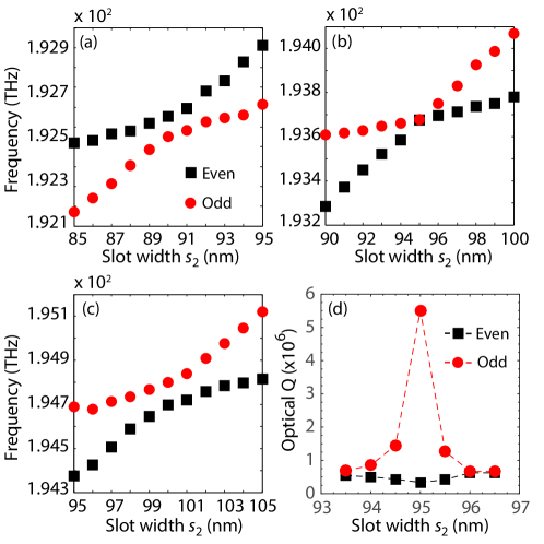
Figure 7(a-c) shows anti-crossing curves obtained where one slot width () is fixed and the other is swept from nm to nm. In this case, the cavity mode eigenfrequencies anti-cross with a minimal splitting achieved for the symmetric situation. The odd and even supermode branches of the anti-crossing curves were identified in Fig. 7 by looking at the parity of electric field profile of the simulated eigenmodes at the center of the anti-crossing (here we label the branches by the parity of the supermodes at the center of the anti-crossing curve). Notice that the lower frequency branch for slot width nm (Fig. 7(a)) is the odd cavity supermode, whereas the higher frequency branch for slot width nm (Fig. 7(c)) has odd parity. For the in-between case of nm, the splitting at the center of the anti-crossing curve is approximately zero ( GHz), as it must be if the parity of the upper and lower frequency supermode branches swap. The possibility to control the supermode frequency splitting in this way provides a unique way to tune the strength of the -coupling according to Eq. (9).
In addition to tuning the cavity supermode splitting, adjusting the air slot sizes may also be used to tune the absolute and relative optical -factor of the two cavity supermodes. Figure 7(d) plots the simulated radiation-limited -factor for the two cavity supermodes as the slot widths are adjusted and the cavity modes sweep through the anti-crossing point. At the center of the anti-crossing curve the two cavity supermodes are to a good approximation even and odd parity modes around the plane, which as we pointed out earlier results in a significant difference in their -factor. Motion of the outer photonic crystal slabs or the central nanobeam will also change the relative air slot sizes, thus changing the radiation damping of the optical cavity supermodes. As noted in recent theoretical work Yanay et al. (2016), this dissipative optomechanical coupling can lead to interference of the quantum noise entering the cavity mode system. This in turn can be used to cool the coupled mechanical resonator to the quantum ground-state even in the unresolved sideband regime (bad-cavity limit). More relevantly, in the case of a predominantly coupled system, this effect can be used to reduce the parasitic linear back-action and enable continuous measurements of the mechanical motion.
IV Mechanical Resonances
Having considered the optical cavity modes of the double-slotted planar photonic crystal, we now analyze the mechanical modes of the structure. In order to support mechanical resonances the photonic crystal slabs are suspended. The optical modes can interact with both flexural and localized acoustic modes of the central nanobeam. In Sec. IV.1, we present the flexural modes of the structure. We show that higher orders flexural modes are found to exist up to 1 GHz with significant optomechanical coupling, making them suitable for operation in the resolved sideband regime, where the optical linewidth is much smaller than the mechanical frequency Aspelmeyer et al. (2014). In Sec. IV.2, we show that the defect developed to form the optical cavity also gives rise to a localized acoustic resonance of a few GHz frequency.
IV.1 Flexural mechanical resonances

The outer slabs and nanobeam behave as three independent mechanical resonators supporting various in-plane and out-of-plane flexural mechanical resonances. Here, we focus on the in-plane flexural modes that are asymmetric with respect to the plane mirror operator (), and symmetric with respect to the plane mirror operator (), about the center of the structure. These flexural modes are represented in Fig. 8 with exaggerated deformation profiles. Since our main focus will be on the fundamental resonances, we denote the fundamental in-plane flexural modes of the two outer slabs and nanobeam as , and respectively. Their respective frequencies are denoted , and .
In our design, the outer slabs are suspended by tethers of length 2.5 m and width 150 nm, yielding fundamental in-plane flexural resonance of MHz. As shown in Fig. 8 (a), these modes correspond to a uniform displacement of the whole slabs. The displacement of one outer slab causes a uniform change of the width of the adjacent slot, and hence a change of the optical supermode frequencies. The in-plane slab modes provide degrees of freedom for the electromechanical tuning of the slot widths.
In Fig. 8 (b), we plot the displacement profiles of the first three lowest frequency ( MHz, MHz and MHz) nanobeam in-plane flexural modes of symmetry . The -polarized electric field profiles are plotted in the inset for both the odd and even optical supermodes . The finite extent of the optical modes along the -axis of the photonic crystal structure limits the region of the nanobeam that will contribute to the optomechanical interaction. As a result, the nanobeam displacement amplitude can be approximated by a net effective displacement of the whole nanobeam , causing one slot width to change by an amount and the other to change by . Because of this asymmetric displacement, the optomechanical couplings of these flexural mode to the individual slot modes and are expected to be equal and of opposite sign. This favors the quadratic and linear cross-mode interaction terms introduced in Eqs. (4) and (9).
Higher order flexural modes of the nanobeam have been identified with frequencies up to GHz and are summarized in table 1. Assuming a moderate optical quality factor of , the resolved-sideband regime condition () could be met with a flexural mode of frequency MHz.
| [MHz] | 10.8 | 56 | 130 | 227 | 340 | 467 | 605 | 746 | 884 | 1025 |
|---|---|---|---|---|---|---|---|---|---|---|
| [fm] | 15.8 | 6.6 | 4.2 | 3.1 | 2.5 | 2.2 | 1.9 | 1.7 | 1.6 | 1.5 |
| [pg] | 3.1 | 3.4 | 3.6 | 3.9 | 3.9 | 3.8 | 3.8 | 3.8 | 3.8 | 3.6 |
IV.2 Localized phononic crystal resonance
In Sec. III.2 we described how to localize optical waveguide modes of the double-slotted photonic crystal waveguide propagating by engineering a perturbation to the waveguide unit cell in the propagation direction. In particular, we analyzed the photonic bandstructure of the waveguide unit cell and designed a defect based on a combination of change in the lattice constant and change in the central nanobeam hole aspect ratio. Here we study the phononic bandstructure of the nanobeam unit cell and show that our choice of photonic crystal defect parameters makes the nanobeam compatible with the localization of an GHz-frequency acoustic resonance.
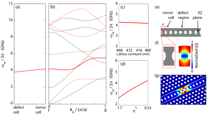
Figure 9(a) and 9(b) show the FEM-simulated acoustic bandstructure of the nanobeam unit cell and the frequency shift of the breathing mode band at the -point as the nanobeam transitions from the mirror unit cell geometry to the defect unit cell geometry. The breathing mode band is shown as a solid red curve. The nanobeam unit cell and the corresponding normalized displacement field profile of the breathing mode are depicted in Figs. ‘9(e-g). The localized breathing mode is drawn from the -point of the bandstructure in order to have a significant optomechanical coupling to the optical mode Eichenfield et al. (2009b).
Figure 9(c) and 9(d) detail separately the shifts of -point frequency of the breathing mode caused by the perturbation in the lattice constant and hole ellipticity of the nanobeam. Increasing the aspect ratio will push the breathing mode frequency down into the band gap of the unperturbed mirror cells, while decreasing the lattice constant slightly increases the frequency of the -point mode. As summarized in Fig. 9(a), the same defect used to localize the photonic crystal resonances satisfies the conditions to localize a phononic crystal resonance. Note that, in contrast to the mechanical flexural modes, the displacement of the localized breathing mode is symmetric with respect to so the optomechanical coupling to this mode is expected to be the same for both and . Therefore, the breathing mode is expected to have negligible linear cross-mode and quadratic coupling strengths. Nevertheless, the breathing mode presents the advantage of being well in the resolved sideband regime and could potentially be used as an auxiliary mechanical mode in multimode optomechanically induced transparency schemes as proposed in Refs. Fan et al. (2015); Ojanen and Børkje (2014).
V Optomechanical Coupling Relations
With knowledge of the optical and mechanical properties of the double slotted waveguide cavity, we can now turn to the calculation of the different optomechanical coupling factors. We utilize a perturbation theory of Maxwell’s equations Johnson et al. (2002) suitable for dealing with both spatial shifts in the dielectric boundaries of the cavity structure as well as stress-induced modifications of the local dielectric constant of the deformed structure. Applying first-order perturbation theory to the numerically computed unperturbed optical field profiles and mechanical field profiles allows us to evaluate both the linear self-mode coupling and the linear cross-mode coupling for the nanobeam flexural modes Braginsky et al. (2002); Miao et al. (2009a); Zhao et al. (2009). By considering the perturbation theory to second-order yields the strength of the quadratic coupling in our structure. Finally, we consider the modification of the coupling strengths due to deviations of the structure from the symmetric equilibrium position of the central nanobeam and outer slabs.
V.1 Linear self-mode optomechanical coupling
Maxwell’s equations in a source-free, linear dielectric medium, yields the following eigenvalue equation for the electric field,
| (10) |
where we have used the Dirac notation for the electric field eigenstate with harmonic time dependence . Here, is the speed of light in vacuum, and is a dielectric constant which is a function of the spatial coordinate (and most generally a tensor). We are interested in the change in the modal frequency due to an infinitesimal perturbation to the dielectric structure. The first-order correction term to the mode frequency is expressed as
| (11) |
where is the unperturbed dielectric constant of the structure, and are electric field and frequency of the harmonic optical mode of interest, , and depends upon the type of perturbation to the dielectric structure.
The change in dielectric constant due to mechanical displacement arises from two main contributions. The first contribution is due to shifting of the interface boundary between two dielectric media. In this case the dielectric function is a high-contrast step function which translates displacements normal to the boundary into local modifications of the dielectric seen by the electric field. As proposed by Johnson, et al., in Ref. Johnson et al. (2002), the appropriate perturbation theory in this so-called moving boundary (MB) problem is given by,
| (12) |
where is the dielectric constant of medium 1 (2) at any point in the boundary surface between two media of differing dielectric constant, , , () is the magnitude of the unperturbed electric (displacement) field polarized in the plane (out of the plane) of the boundary surface between medium 1 and medium 2, and is the outward unit vector normal pointing from medium 1 into medium 2 on boundary . Here, is the normalized displacement field of the mechanical mode of interest with maximum displacement equal to unity, . We can also define an effective mass of the mechanical mode in terms of ,
| (13) |
where is the mass density of the dielectric material defining the optomechanical structure. This effective mass is the appropriate motional mass for evaluating the zero-point fluctuation amplitude, , of the generalized amplitude coordinate corresponding to the point of maximum amplitude of the mechanical mode.
The second contribution to the linear self-mode coupling is due to the photoelastic effect, resulting from the change of the dielectric constant due to the local strain induced by the mechanical displacement. The first-order perturbation to the dielectric tensor is given by,
| (14) |
where is the unperturbed dielectric tensor, is the permittivity of free space, is the fourth rank photoelastic tensor, and is the symmetric strain tensor. For an isotropic medium this simplifies to,
| (15) |
in index notation. In matrix form,
| (16) | ||||
The resulting first-order photoelastic (PE) correction to the optical frequency is
| (17) |
In the structures studied here, which are made by etching patterns into a thin-film of silicon, the only two media are silicon and vacuum. As such, for the PE contribution to the linear self-mode coupling we utilize the photoelastic tensor coefficients for silicon in evaluating the integral in the numerator Biegelsen (1975): , and .
We begin by considering the calculation of and for our double-slotted photonic crystal device, i.e., the linear optomechanical couplings of the optical supermodes and to the fundamental in-plane flexural mode of either outer slab (we choose in this case). Table 2 displays the numerically computed coefficients using the perturbation theory described above in terms of the unperturbed optical and mechanical fields. and can also be approximated by fitting the anti-crossing curves of Fig. 7 using the dispersion relation given in Eq. (5). The approximate dispersion relation fit values for the linear couplings are also shown in Tab. 2, and compare well to the exact perturbation theory values despite the fact that the couplings derived from the dispersion relations using Eqs. (3) and (5) neglect cross-coupling terms between and mediated by the mechanics.
The localized breathing mode of the central nanobeam was found by FEM simulations to be at a mechanical frequency of GHz, with linear coupling rates of 249 kHz and 163 kHz to the supermodes, respectively, where we have used the notation .
| First order perturbation theory | Anti-crossing fit | ||
| Slot width | |||
| nm | GHz/nm | GHz/nm | GHz/nm |
| 90 | 55.05 | 57.79 | 51.13 |
| 95 | 51.81 | 53.62 | 48.81 |
| 100 | 41.12 | 47.69 | 44.45 |
V.2 Linear cross-mode optomechanical coupling
By analogy with Eq. (11), the first order perturbation term for the linear cross-mode coupling , where , can be written as Chang et al. (2011)
| (18) |
In the case of the double-slotted photonic crystal of this work, we have for the shifting boundaries contribution to the cross-mode coupling between the supermodes and at the symmetric () equilibrium position (center of the anti-crossing curve of Fig. 7):
| (19) |
Note that for the flexural mechanical modes of the photonic crystal structure (either slab or central nanobeam modes) we expect this to be the dominant contribution to the optomechanical coupling. Expanding and in terms of the slot modes, and neglecting the cross terms such as due to the small spatial overlap between the fields of the modes localized in separated slots, we obtain Eq. (4) again, .
Consider now the flexural modes of the central nanobeam. At the symmetric () equilibrium position, the nanobeam’s in-plane flexural modes are such that . Therefore, at the center of the anti-crossing curve is maximal and equal to the linear coupling of the nanobeam mode to the slot modes. Table 3 shows the numerically computed linear cross-mode coupling rate for the fundamental and higher order nanobeam in-plane flexural modes along with their respective frequencies simulated for slot sizes nm using Eq. (19). Due to the tight localization of optical modes (see Fig. 8) we find there is still significant coupling to higher order flexural modes of frequencies all the way up to GHz. For the numerical simulations of the optical supermodes of the double-slotted photonic crystal structure we also find that the radiation-limited optical quality factor is theoretically equal to and for the odd and even modes respectively. Therefore, as noted earlier, we can expect mechanical modes of frequencies MHz to be in the resolved-sideband regime.
V.3 Quadratic optomechanical coupling
By extending the perturbation theory to the second order, it is also possible to calculate the -coupling strength Cohen-Tannoudji et al. (1977); Kaviani et al. (2015); Rodriguez et al. (2011); Safavi-Naeini (2013). We obtain, for a given optical mode
| (20) |
In the case of the supermodes and of the symmetric double-slotted photonic crystal structure (), the first term vanishes and the only contribution to the -coupling comes from the second term. For optical splittings such that ,
| (21) | ||||
which is what we obtained in Eq. (9). In Eq. (21) we only consider the contribution from the fundamental optical cavity supermodes because the frequency splitting between them is relatively small. Note that another approach Kaviani et al. (2015) has shown that using a large number of spatially overlapping optical modes rather than decreasing the splitting of just two optical modes (as in our case) can also lead to significant -coupling strengths. The values of are summarized in Tab. 3 for the nanobeam in-plane flexural modes up to MHz. Here we assume an optical supermode frequency splitting of GHz, which is close to the minimum splitting based on the estimated optical quality factors which allows the optical supermodes to be selectively excited and interrogated.
| [MHz] | [kHz] | [Hz] |
|---|---|---|
| 10.8 | 1020 | 1000 |
| 56 | 402 | 160 |
| 130 | 271 | 73 |
| 227 | 208 | 43 |
| 340 | 167 | 28 |
| 467 | 126 | 15 |
| 605 | 81 | 7 |
| 746 | 44 | 2 |
| 884 | 20 | 0.4 |
| 1025 | 8 | 0.07 |
V.4 Coupling coefficients as a function of a static displacement of the nanobeam
In the analysis of the optomechanical coupling coefficients described above in Section V.1-V.3 we considered a symmetric double-slotted structure with equal slot widths (equilibrium position ), and thus the calculations were done for the optical supermodes . In practice, we could find this symmetric condition by tuning one of the slabs to adjust the relative slots sizes until the optical frequency spectrum was at the center of the anti-crossing curve as shown in Fig. 7. Far away from the center of the anti-crossing, however, the optical supermodes correspond more closely to the individual slot modes and , and we expect different optomechanical coupling strengths. Here we describe how the optomechanical coupling coefficients change upon a large, static displacement of the central nanobeam which takes us far from the symmetric condition near the center of the anti-crossing curve.
From the approximate analytical expression of the supermode dispersion (see Eq. 5), we derive here approximate expressions for , and as a function of the static displacement amplitude of the fundamental nanobeam mode:
| (22) | ||||
| (23) | ||||
| (24) |
where . Note as per our previously established convention.
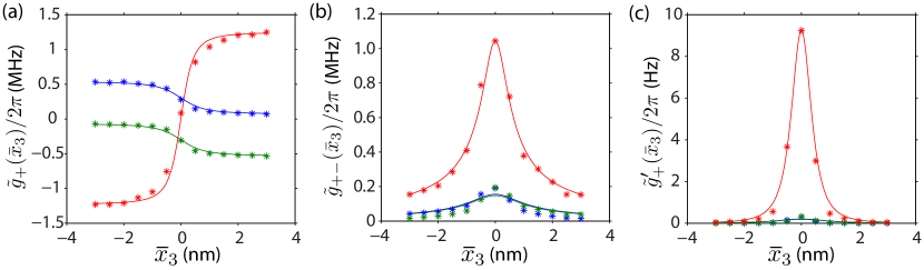
As discussed in Sec. IV.1, can be approximated by a static displacement of the whole nanobeam. Using the perturbative calculation of the optomechanical coupling coefficients from the numerically simulated optical and mechanical fields one can then obtain , and by simulating a structure with the nanobeam displaced from its equilibrium position by (this becomes the new “unperturbed” structure in our perturbative calculations). Here we consider a structure with nominal slot widths of nm at equilibrium, and the displacement of the nanobeam from its equilibrium position is swept from nm to nm in steps of nm. At each position we calculate the coupling coefficients between the optical supermodes and the fundamental in-plane flexural mode of the nanobeam. The results of these simulations and calculations are plotted in Fig. 10. A fit to the numerically calculated coefficients using Eqs. (22-24) show very good agreement.
These results confirm our previous speculations that far from the symmetric equilibrium position the linear optomechanical coupling is the dominant optomechanical interaction between the optical supermodes and the flexural modes of the central nanobeam, while at symmetric equilibrium position of the beam () the optomechanical interaction is predominantly -coupling. The linear cross-mode coupling between the optical supermodes is also maximal at , however its effects are strongly suppressed in the present case since the splitting between the optical resonances (here GHz) is much larger than the mechanical frequency of the fundamental in-plane nanobeam mode ( MHz) Chen et al. (2015); Miao et al. (2009b). Experimentally, a static displacement of the whole nanobeam by can be mimicked by displacing both outer slabs in the same direction by an amount . Conversely, a change in the equilibrium slot size can be achieved by displacing both outer slabs in opposite directions. In our recent experimental realization of the double-slotted photonic crystal cavity structure we used this tuning degree of freedom by integrating a set of independent capacitors on the outer slabs Paraïso et al. (2015).
VI Summary
We presented a general formalism for studying linear and quadratic coupling of mechanical motion with optical fields in a multimoded optical cavity. This formalism is used to model and design a double-slotted photonic crystal cavity structure previously studied by us experimentally in Ref. Paraïso et al. (2015). The device supports two high- optical resonances at telecommunication wavelengths and mechanical resonances spanning both the unresolved sideband and resolved sideband regimes. We find that depending on the symmetry of the photonic crystal structure, the optical supermodes can be made to interact either linearly or quadratically with mechanical motion. In particular, we show that the splitting between the optical supermodes can be strongly suppressed, which provides a significant enhancement of the quadratic () coupling. The linear and quadratic optomechanical coupling coefficients are calculated using perturbation theory and finite-element-method simulations of the (unperturbed) optical modes and mechanical displacement fields. The simulated optical quality factors of the photonic crystal cavity are calculated to be of order , placing mechanical modes of frequencies MHz in the resolved sideband regime. With such parameters, it is shown that the designed photonic crystal device can achieve zero-point -couplings as large as kHz for the MHz fundamental in-plane flexural mode of the structure, and Hz for a higher order flexural mode of frequency MHz in the resolved sideband regime, several orders of magnitude larger than in any other proposed optomechanical system to date. Notably, the splitting of the photonic crystal cavity supermodes may be tuned by adjusting the cavity slot widths to a minimal value approaching that of the cavity mode linewidths ( GHz), greatly enhancing the achievable coupling. Although QND measurements of the stored mechanical energy will require substantially lower optical cavity losses Miao et al. (2009a); Ludwig et al. (2012); Paraïso et al. (2015), with this scale of -coupling it is feasible to consider a number of other interesting experiments with slightly less restrictive parameters. These include the quantum measurement of phonon or photon shot noise Clerk et al. (2010), or utilizing interference of quantum noise in the bad-cavity limit Yanay et al. (2016), a continuous position measurement of . The latter measurement requires additional dissipative optomechanical coupling, which the photonic crystal cavity structure of this work also possesses.
Acknowledgements.
This work was supported by the AFOSR Hybrid Nanophotonics MURI (FA9550-12-1-0024), the Institute for Quantum Information and Matter, an NSF Physics Frontiers Center (NSF Grant PHY-1125565) with support of the Gordon and Betty Moore Foundation (GBMF-2644), the Alexander von Humboldt Foundation, and the Max Planck Society.References
- Aspelmeyer et al. (2014) Markus Aspelmeyer, Tobias J. Kippenberg, and Florian Marquardt, “Cavity optomechanics,” Rev. Mod. Phys. 86, 1391–1452 (2014).
- Jayich et al. (2008) AM Jayich, JC Sankey, BM Zwickl, C Yang, JD Thompson, SM Girvin, AA Clerk, F Marquardt, and JGE Harris, “Dispersive optomechanics: a membrane inside a cavity,” New Journal of Physics 10, 095008 (2008).
- Thompson et al. (2008) JD Thompson, BM Zwickl, AM Jayich, Florian Marquardt, SM Girvin, and JGE Harris, “Strong dispersive coupling of a high-finesse cavity to a micromechanical membrane,” Nature 452, 72–75 (2008).
- Ludwig et al. (2012) Max Ludwig, Amir H Safavi-Naeini, Oskar Painter, and Florian Marquardt, “Enhanced quantum nonlinearities in a two-mode optomechanical system,” Physical Review Letters 109, 063601 (2012).
- Miao et al. (2009a) Haixing Miao, Stefan Danilishin, Thomas Corbitt, and Yanbei Chen, “Standard quantum limit for probing mechanical energy quantization,” Phys. Rev. Lett. 103, 100402 (2009a).
- Braginsky et al. (2001) VB Braginsky, SE Strigin, and S Pr Vyatchanin, “Parametric oscillatory instability in fabry–perot interferometer,” Phys. Lett. A 287, 331–338 (2001).
- Braginsky et al. (2002) Vladimir B Braginsky, Sergey E Strigin, and Sergey P Vyatchanin, “Analysis of parametric oscillatory instability in power recycled ligo interferometer,” Phys. Lett. A 305, 111–124 (2002).
- Braginsky and Vyatchanin (2002) VB Braginsky and SP Vyatchanin, “Low quantum noise tranquilizer for fabry–perot interferometer,” Phys. Lett. A 293, 228–234 (2002).
- Ojanen and Børkje (2014) Teemu Ojanen and Kjetil Børkje, “Ground-state cooling of mechanical motion in the unresolved sideband regime by use of optomechanically induced transparency,” Phys. Rev. A 90, 013824 (2014).
- Fan et al. (2015) Linran Fan, King Y. Fong, Menno Poot, and Hong X. Tang, “Cascaded optical transparency in multimode-cavity optomechanical systems,” Nat. Commun. 6, 5850 (2015).
- Heinrich et al. (2011) Georg Heinrich, Max Ludwig, Jiang Qian, Björn Kubala, and Florian Marquardt, “Collective dynamics in optomechanical arrays,” Phys. Rev. Lett. 107, 043603 (2011).
- Zhang et al. (2012) Mian Zhang, Gustavo S. Wiederhecker, Sasikanth Manipatruni, Arthur Barnard, Paul McEuen, and Michal Lipson, “Synchronization of micromechanical oscillators using light,” Phys. Rev. Lett. 109, 233906 (2012).
- Bagheri et al. (2013) Mahmood Bagheri, Menno Poot, Linran Fan, Florian Marquardt, and Hong X. Tang, “Photonic cavity synchronization of nanomechanical oscillators,” Phys. Rev. Lett. 111, 213902 (2013).
- Matheny et al. (2014) Matthew H. Matheny, Matt Grau, Luis G. Villanueva, Rassul B. Karabalin, M. C. Cross, and Michael L. Roukes, “Phase synchronization of two anharmonic nanomechanical oscillators,” Phys. Rev. Lett. 112, 014101 (2014).
- Xu and Li (2013) Xun-Wei Xu and Yuan-Jie Li, “Antibunching photons in a cavity coupled to an optomechanical system,” J. Phys. B At. Mol. Opt. Phys. 46, 035502 (2013).
- Flayac et al. (2015) Hugo Flayac, Dario Gerace, and Vincenzo Savona, “An all-silicon single-photon source by unconventional photon blockade.” Sci. Rep. 5, 11223 (2015).
- Lemonde et al. (2014) Marc-Antoine Lemonde, Nicolas Didier, and Aashish A. Clerk, “Antibunching and unconventional photon blockade with Gaussian squeezed states,” Phys. Rev. A 90, 063824 (2014).
- Lörch and Hammerer (2015) Niels Lörch and Klemens Hammerer, “Sub-Poissonian phonon lasing in three-mode optomechanics,” Phys. Rev. A 91, 061803 (2015).
- Kippenberg et al. (2005) TJ Kippenberg, H Rokhsari, T Carmon, A Scherer, and KJ Vahala, “Analysis of radiation-pressure induced mechanical oscillation of an optical microcavity,” Phys. Rev. Lett. 95, 033901 (2005).
- Krause et al. (2012) Alexander G. Krause, Martin Winger, Tim D. Blasius, Qiang Lin, and Oskar Painter, “A high-resolution microchip optomechanical accelerometer,” Nat Photon 6, 768–772 (2012).
- Schmidt et al. (2012) Michael Schmidt, Max Ludwig, and Florian Marquardt, “Optomechanical circuits for nanomechanical continuous variable quantum state processing,” New Journal of Physics 14, 125005 (2012).
- Winger et al. (2011) M. Winger, T. D. Blasius, T. P. Mayer Alegre, A. H. Safavi-Naeini, S. Meenehan, J. Cohen, S. Stobbe, and O. Painter, “A chip-scale integrated cavity-electro-optomechanics platform,” Opt. Express 19, 24905–24921 (2011).
- Stannigel et al. (2012) K. Stannigel, P. Komar, S. J. M. Habraken, S. D. Bennett, M. D. Lukin, P. Zoller, and P. Rabl, “Optomechanical quantum information processing with photons and phonons,” Phys. Rev. Lett. 109, 013603 (2012).
- Chang et al. (2011) DE Chang, Amir H Safavi-Naeini, Mohammad Hafezi, and Oskar Painter, “Slowing and stopping light using an optomechanical crystal array,” New Journal of Physics 13, 023003 (2011).
- Safavi-Naeini et al. (2011) A H Safavi-Naeini, T P Mayer Alegre, J Chan, M Eichenfield, M Winger, Q Lin, J T Hill, D E Chang, and O Painter, “Electromagnetically induced transparency and slow light with optomechanics.” Nature 472, 69–73 (2011).
- Weis et al. (2010) Stefan Weis, Rémi Rivière, Samuel Deléglise, Emanuel Gavartin, Olivier Arcizet, Albert Schliesser, and Tobias J Kippenberg, “Optomechanically induced transparency.” Science 330, 1520–3 (2010).
- Sankey et al. (2010) Jack C Sankey, Cheng Yang, Benjamin M Zwickl, Andrew M Jayich, and Jack GE Harris, “Strong and tunable nonlinear optomechanical coupling in a low-loss system,” Nature Physics 6, 707–712 (2010).
- Lee et al. (2015) D Lee, M Underwood, D Mason, A B Shkarin, S W Hoch, and J G E Harris, “Multimode optomechanical dynamics in a cavity with avoided crossings.” Nat. Commun. 6, 6232 (2015).
- Chen et al. (2015) X. Chen, C. Zhao, S. Danilishin, L. Ju, D. Blair, H. Wang, S. P. Vyatchanin, C. Molinelli, A. Kuhn, S. Gras, T. Briant, P.-F. Cohadon, A. Heidmann, I. Roch-Jeune, R. Flaminio, C. Michel, and L. Pinard, “Observation of three-mode parametric instability,” Phys. Rev. A 91, 033832 (2015).
- Grudinin et al. (2010) Ivan S Grudinin, Hansuek Lee, Oskar Painter, and Kerry J Vahala, “Phonon laser action in a tunable two-level system,” Physical review letters 104, 083901 (2010).
- Doolin et al. (2014) C. Doolin, B. D. Hauer, P. H. Kim, a. J R MacDonald, H. Ramp, and J. P. Davis, “Nonlinear optomechanics in the stationary regime,” Phys. Rev. A 89, 1–6 (2014).
- Massel et al. (2012) Francesco Massel, Sung Un Cho, Juha-Matti Pirkkalainen, Pertti J Hakonen, Tero T Heikkilä, and Mika A Sillanpää, “Multimode circuit optomechanics near the quantum limit.” Nat. Commun. 3, 987 (2012).
- Evans et al. (2015) Matthew Evans, Slawek Gras, Peter Fritschel, John Miller, Lisa Barsotti, Denis Martynov, Aidan Brooks, Dennis Coyne, Rich Abbott, Rana X. Adhikari, Koji Arai, Rolf Bork, Bill Kells, Jameson Rollins, Nicolas Smith-Lefebvre, Gabriele Vajente, Hiroaki Yamamoto, Carl Adams, Stuart Aston, Joseph Betzweiser, Valera Frolov, Adam Mullavey, Arnaud Pele, Janeen Romie, Michael Thomas, Keith Thorne, Sheila Dwyer, Kiwamu Izumi, Keita Kawabe, Daniel Sigg, Ryan Derosa, Anamaria Effler, Keiko Kokeyama, Stefan Ballmer, Thomas J. Massinger, Alexa Staley, Matthew Heinze, Chris Mueller, Hartmut Grote, Robert Ward, Eleanor King, David Blair, Li Ju, and Chunnong Zhao, “Observation of Parametric Instability in Advanced LIGO,” Phys. Rev. Lett. 114, 161102 (2015).
- Paraïso et al. (2015) Taofiq K. Paraïso, Mahmoud Kalaee, Leyun Zang, Hannes Pfeifer, Florian Marquardt, and Oskar Painter, “Position-Squared Coupling in a Tunable Photonic Crystal Optomechanical Cavity,” Phys. Rev. X 5, 041024 (2015).
- Johnson and Joannopoulos (2001) Steven G. Johnson and J. D. Joannopoulos, “Block-iterative frequency-domain methods for maxwell’s equations in a planewave basis,” Opt. Express 8, 173–190 (2001).
- Eichenfield et al. (2009a) Matt Eichenfield, Ryan Camacho, Jasper Chan, Kerry J Vahala, and Oskar Painter, “A picogram-and nanometre-scale photonic-crystal optomechanical cavity,” Nature 459, 550–555 (2009a).
- Chan et al. (2009) Jasper Chan, Matt Eichenfield, Ryan Camacho, and Oskar Painter, “Optical and mechanical design of a ”zipper” photonic crystal optomechanical cavity,” Opt. Express 17, 3802 (2009).
- (38) COMSOL Multiphysics, version 3.5a.
- Srinivasan and Painter (2002) Kartik Srinivasan and Oskar Painter, “Momentum space design of high- photonic crystal optical cavities,” Opt. Express 10, 670–684 (2002).
- Yanay et al. (2016) Yariv Yanay, Jack C. Sankey, and Aashish A. Clerk, “Quantum backaction and noise interference in asymmetric two-cavity optomechanical systems,” Phys. Rev. A 93, 063809 (2016).
- Eichenfield et al. (2009b) Matt Eichenfield, Jasper Chan, Ryan Camacho, Kerry Vahala, and Oskar Painter, “Optomechanical crystals,” Nature 462, 78–82 (2009b).
- Johnson et al. (2002) Steven G Johnson, Mihai Ibanescu, MA Skorobogatiy, Ori Weisberg, JD Joannopoulos, and Yoel Fink, “Perturbation theory for maxwell’s equations with shifting material boundaries,” Phys. Rev. E 65, 066611 (2002).
- Zhao et al. (2009) Chunnong Zhao, Li Ju, Haixing Miao, Slawomir Gras, Yaohui Fan, and David G Blair, “Three-mode optoacoustic parametric amplifier: a tool for macroscopic quantum experiments,” Phys. Rev. Lett. 102, 243902 (2009).
- Biegelsen (1975) DK Biegelsen, “Frequency dependence of the photoelastic coefficients of silicon,” Physical Review B 12, 2427 (1975).
- Cohen-Tannoudji et al. (1977) Claude Cohen-Tannoudji, Bernard Diu, and Frank Lalo , Quantum Mechanics, Vol. 2 (Hermann, Paris, 1977) Chap. 11.
- Kaviani et al. (2015) Hamidreza Kaviani, Chris Healey, Marcelo Wu, Roohollah Ghobadi, Aaron Hryciw, and Paul E. Barclay, “Nonlinear optomechanical paddle nanocavities,” Optica 2, 271–274 (2015).
- Rodriguez et al. (2011) Alejandro W Rodriguez, Alexander P McCauley, Pui-Chuen Hui, David Woolf, Eiji Iwase, Federico Capasso, Marko Loncar, and Steven G Johnson, “Bonding, antibonding and tunable optical forces in asymmetric membranes.” Opt. Express 19, 2225–2241 (2011).
- Safavi-Naeini (2013) Amir H. Safavi-Naeini, Quantum Optomechanics with Silicon Nanostructures, Ph.D. thesis, California Institute of Technology (2013).
- Miao et al. (2009b) H. Miao, C. Zhao, L. Ju, and D. G. Blair, “Quantum ground-state cooling and tripartite entanglement with three-mode optoacoustic interactions,” Phys. Rev. A 79, 063801 (2009b).
- Clerk et al. (2010) A. A. Clerk, Florian Marquardt, and J. G. E. Harris, “Quantum measurement of phonon shot noise,” Phys. Rev. Lett. 104, 213603 (2010).