Large Cross-Phase Modulations at the Few-Photon Level
Abstract
We demonstrate an efficient cross-phase modulation (XPM) based on a closed-loop double- system. The property of the double- medium can be controlled by changing the phases of the applied optical fields. This phase-dependent XPM scheme can achieve large phase modulations at low-light intensities without requiring cavities or tightly focusing of laser beams. With this scheme, we observe a -level phase shift with two pulses both consisting of 8 photons in cold rubidium atoms. Such novel scheme provides a simple route to generate strong interactions between photons and may have potential applications in all-optical quantum signal processing.
pacs:
03.67.-a, 32.80.Qk, 42.25.Hz, 42.50.GyThe realization of large cross-phase modulations (XPM) at low-light intensities, ultimately at the single-photon level, is an important but challenging task in quantum information science ZeilingerQI ; NielsenQI ; YamamotoQND . To reach this goal, one often requires high-finesse cavities to enhance nonlinear interactions between photons TurchetteCavityXPM ; FushmanCavityXPM . However, cavity-based experiments require many compromises such as balancing cavity bandwidth and light-matter coupling strength, which remain technical difficulties. Another promising approach for generating strong photon-photon interaction is electromagnetically induced transparency (EIT) HarrisEIT ; LukinEIT ; FleischhauerEIT , but according to the theoretical predictions by Harris and coworkers, the cross-phase shift of the EIT-based Kerr medium in free space has an upper limit of order 0.1 radians at the single-photon level HarrisSLNO . To date, EIT-based XPM on the order of micro-radians per photon has been observed in cold atoms LoXPM ; SteinbergXPM and Rb-filled fiber system GaetaXPM . In recent years, to overcome this upper limit there have been many theoretical proposals and experimental studies on this subject including double slow-light schemes LukinDSLXPM ; ShiauDSXPM , stationary light schemes LukinSL ; YuSLXPM , cavity EIT schemes MuckeCavityEIT ; ZhuCavityEIT , or Rydberg EIT schemes FleischhauerRydbergXPM ; AdamsRydbergEIT ; AdamsRydbergBlockade ; LukinRydbergBlockade ; DurrRydbergEIT ; HofferberthRydbergEIT . Very recently, two research teams have overcame this upper limit and observed single-photon cross-phase shifts of and by using cavity EIT VuleticCavityXPM and Rydberg EIT DurrRydbergXPM , respectively. This is a great progress toward implementing a photon-photon gate.
Here we report an experimental observation of a novel XPM scheme based on a phase-dependent double- system. With this scheme, we observe a large cross-phase shift of 3.61.0 radians induced by a light pulse containing around 8 photons in cold rubidium atoms. This XPM scheme does not require cavities or Rydberg atoms, which provides a simple route to generate strong interactions between photons and obtain large cross-phase shifts per photon.
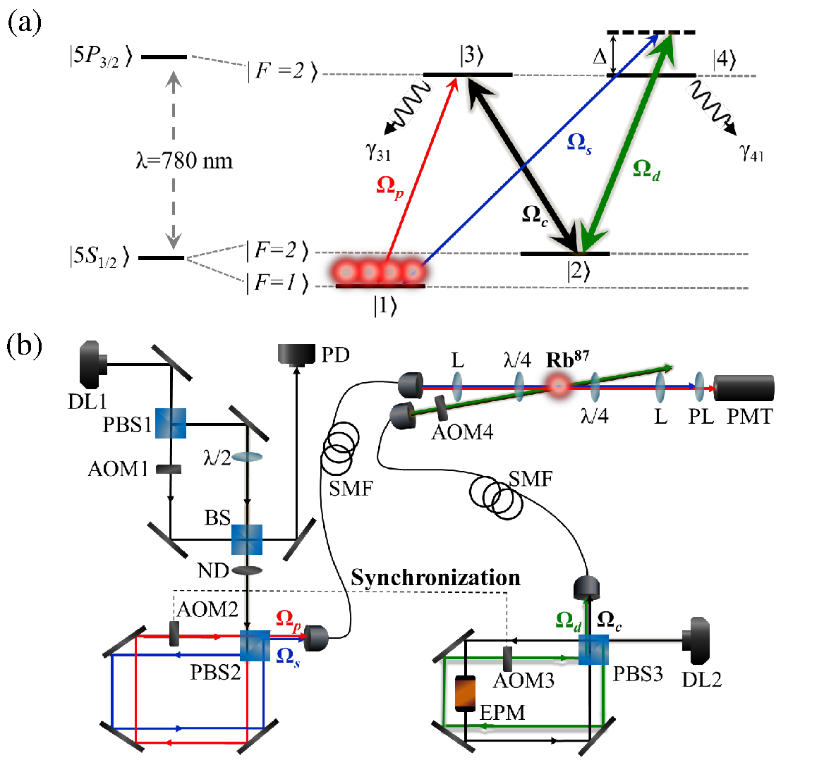
In the present study, we investigate a closed-loop double- XPM in a laser-cooled atomic system, as depicted in Fig. 1(a). Cold atomic gas with an optical depth of approximately 50 is produced in a dark spontaneous-force optical trap (SPOT) KetterleSPOT .A strong coupling field ( denotes its Rabi frequency) drives the transition to create a transparent medium for a weak probe pulse (, ) through quantum interference. The coupling and probe fields form the first -type EIT system. The second -type EIT system is created by a strong driving field (, ) and a weak signal pulse (, ). In the experiment, the coupling and probe fields are right circularly polarized () while the driving and signal fields are left circularly polarized (). The four laser fields drive the -line transition of the atoms to form the closed-loop double- EIT system, as shown in Fig. 1(a).
A schematic diagram of the experimental setup is shown in Fig. 1(b). The probe and signal fields are produced using a single diode laser (DL1); the coupling and driving fields are produced using another diode laser (DL2). DL2 is directly injection locked using an external cavity diode laser (ECDL, TOPTICA DL 100) with a laser linewidth of around 1 MHz. One beam from the ECDL is sent through a 6.8-GHz electro-optic modulator (EOM, New Focus 4851). DL1 is injection locked by an intermediate laser seeded with the high-frequency sideband of the EOM output. The above arrangement is capable of completely eliminating the influence of the carrier of the EOM output on DL1. The probe beam is overlapped with the signal beam on a polarization beam splitter (PBS2), and then sent to a single-mode fiber (SMF) to obtain the optimal spatial mode-matching. The diameters of the probe (signal) and coupling (driving) beams are 0.2 mm and 3 mm, respectively. These two beams propagate at an angle of around . All of the laser fields are switched on and off via acousto-optic modulators (AOMs). We utilize AOM1 to control the widths of the probe and signal pulses. The coupling and driving fields are switched on and off via AOM4 [see Fig. 1(b)]. The experimental data are detected by a photomultiplier tube module (PMT, Hamamatsu H6780-20 and C9663) with a conversion gain of around V/W, and then recorded using an oscilloscope (Agilent MSO6034A) throughout the experiment. The number of photons of the few-photon pulses (probe and signal pulses) are also checked by a single-photon counting module (SPCM, Perkin-Elmer SPCM-AQR-13).
When conducting the phase-dependent double- experiment, an electro-optic phase modulator (EPM, Thorlabs EO-PM-NR-C1) is applied to vary the phase of the coupling field (). Furthermore, to stabilize the relative phase of the four laser fields, two main setups are utilized in this experiment. (i) The optical paths of the probe and signal (coupling and driving) fields are arranged in the configuration of a Sagnac-like interferometer to reduce the path fluctuations between these two beams, as shown in Fig. 1(b). (ii) AOM2 and AOM3 are driven by the same RF generator through an RF power splitter (Mini-Circuits ZMSC-2-1+).
We utilize a sensitive beat-note interferometer to measure the cross-phase shift of the weak probe pulse. The probe beam is first split into the transmitted and reflected beams by PBS1 in order to establish the beat-note interferometer [see Fig. 1(b)]. The transmitted beam passes through the AOM1, which has a driving frequency of 80 MHz, to generate a first-order beam for the probe pulse and then recombines with the reflected beam from the PBS1 on a beam splitter (BS). One beam from the BS is called the reference beat notes, which is directly received by a photo detector (PD, New Focus 1801). The other beam, corresponding to the probe beat notes, is detected by a PMT after propagating through the double- medium. The phase shift of the probe pulse is measured by directly comparing the reference and probe beat notes. In this experiment, only the phase shift within 1 s of the end of the probe pulse is measured in order to acquire the steady-state results. The probe transmission is simultaneously obtained from the amplitude of the probe beat notes. The experimental setup and details of the beat-note interferometer can be found in Ref. LoBeatNote .
To theoretically analyze the behavior of the probe and signal pulses propagating in the double- EIT medium, we use the Maxwell-Schrödinger equations below:
| (1) |
| (2) |
where and are the Rabi frequencies of the probe and signal pulses, respectively. () describes the phase information carried by the probe (signal) pulse. () is the slowly-varying amplitude of the optical coherence of the probe (signal) transition. () represents the optical depth of the probe (signal) transition, where is the number density of the atoms, () is the atomic absorption cross section of the probe (signal) transition, and is the optical path length of the medium. and represent the total coherence decay rates from the and excited states, respectively. We note that the optical depths of the probe and signal transitions in this experiment are the same () because is equal to by considering three degenerate Zeeman sublevels, as shown in Fig. 1(a).
In the case where the probe and signal fields are very weak (i.e., ), the optical Bloch equations of the slowly-varying amplitudes of the density-matrix elements are given by:
| (3) |
| (4) |
| (5) |
where and are the Rabi frequencies of the coupling and driving transitions, respectively. () describes the phase information carried by the coupling (driving) field. denotes the detuning of the signal transition [see Fig. 1(a)]. represents the dephasing rate of the and ground states. Each parameter in the theoretical model is individually determined from additional experiments as follows: is determined from the separation of the two absorption peaks in the EIT spectrum. is determined from the EIT-based photon-switching effect ChenPS . is derived from the delay time of the slow light pulse HauSlowLt . is , as estimated by the degree of EIT transparency. MHz is the spontaneous decay rate of the excited states. and are both , contributed mostly by the spontaneous decay rate and laser linewidth, as obtained from the spectral width of the one-photon absorption. Assume , = and , the steady-state solutions of Eqs. (1)–(5) for the probe and signal fields are:
| (6) | |||
| (7) |
where , . The terms and represent the incident probe and signal fields, respectively. Under the conditions of and , we obtain a simple steady-state solutions for the probe and signal fields as follows:
| (8) | |||
| (9) |
where the relative phase of the four laser fields, , is defined as . According to Eqs. (8) and (9), when and , the double- medium becomes completely transparent for both the probe and the signal fields. On the other hand, when , the medium becomes opaque and has maximum attenuation for both the probe and the signal fields. This phase-dependent double- system with can be applied in all-optical switching, as previously described ZhuDLambdaPS1 . Here we focus on demonstrating large phase modulations at low-light intensities with this scheme. Of note, the matched propagation of a pair of slow light pulses in the double- medium has been theoretically discussed in Ref. DengDLambda . Recently, the closed-loop double- system can be engineered to achieve broadly tunable light shifts at low-light intensities has also been theoretically studied in Ref. ArtoniXPM .
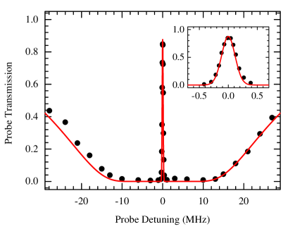
We first measure the transmission of a probe pulse propagating through a three-level -type EIT medium. After all of the lasers and magnetic fields of the dark SPOT are turned off and the coupling field () is switched on for 100 s, the 10-s probe square pulse is switched on to perform the measurement. The experiment is conducted at a repetition rate of 100 Hz. The input power of the probe pulse is set to 1 nW in the EIT experiment. The Rabi frequency of the coupling transition, , is 0.7, corresponding to the coupling laser power of around 0.5 mW. Figure 2 shows the probe transmission as a function of probe detuning. The inset shows the EIT transmission window. The measurement data (circles) are in good agreement with the theoretical curve (red line). The theoretical curve is plotted using the EIT theoretical expression in Ref. LoBeatNote .
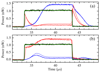
Next, we perform the double- experiment in the pulsed regime. Figure 3 shows a typical experimental data, where , = 13, , and the input powers of both the probe and the signal pulses are set to 1 nW, corresponding to (i.e., ). Here the widths of both the probe and signal pulses are set to 10 s. We utilized the EPM to vary the relative phase [see Fig. 1(b)]. The relative phase is set to 1.5 radians in Fig. 3(a) and 4.5 radians in Fig. 3(b). The solid and dashed lines represent the experimental data and theoretical curves, respectively. The theoretical curves are plotted by numerically solving Eqs. (1)–(5). The black (green) lines are the input probe (signal) pulses, and the blue (red) lines are the transmitted probe (signal) pulses. The group-velocity mismatch of the transmitted probe and signal pulses in Fig. 3 is due to . The experimental data also show that the power of the transmitted light exceeds its input power in the double- system. This light-amplification phenomenon is caused by of the coherent light transfer between two N-type FWM processes ( and ) ChenFWM . For more detailed discussions for the coherent light amplification can be found in the Supplemental Material SM .
Figure 4 shows the experimental data of the double--based XPM at low-light levels. The experimental parameters are the same as those in Fig. 3 except for the optical depth (). We first perform the double- experiment where the input powers of both the probe and the signal pulses are set to 10 pW, corresponding to around 400 photons per pulse. Figure 4(a) and 4(b) show the experimental data of the dependence of the probe transmission and phase shift on the relative phase , respectively, which are in agreement with the theoretical curves. We subsequently perform the double- experiment at the few-photon level. The input powers of both the probe and the signal pulses in Figs. 4(c) and 4(e) are reduced to aroun 1 and 0.2 pW, corresponding to around 40 and 8 photons, respectively. Circles (squares) represent the experimental data of the probe transmission (phase shift). The blue (red) lines are the theoretical curves of the probe transmission (phase shift). Throughout the experiment, the statistical error bar is evaluated using 6 samples. Each sample is averaged 4096, 16384 and 32768 times for the measurement with 400, 40, and 8 incident photons, respectively. All error bars in this paper represent a statistical uncertainty of one standard deviation. We note that under the conditions of and , the probe transmission and phase modulation after propagating through the double- medium are the same according to Eqs. (8) and (9). A detailed theoretical analysis can be found in the Supplemental Material SM .
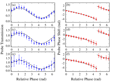
As the number of the probe and signal photons decreases, the error bars of the measurement data become large due to smaller signal-to-noise ratios, as shown in Fig. 4. Although the data in Fig. 4(f) possess a large amount of phase noise of around 1 radians, the measured values are still valid considering the considerable phase shift. For instance, in Fig. 4(f), a maximum phase shift of -4.50.9 radians is measured when the relative phase is set to 4.4 radians. When the signal pulse is absent, we also measure the probe phase shift of -0.90.1 radians which is consistent with the theoretical predictions. Hence, we conclude that a cross-phase shift of 3.61.0 radians induced by a light pulse containing around 8 photons has been realized with this scheme. So far we do not perform the experiment using few-photon pulses containing less than 8 photons because the long-term instability of our experimental system prevents us from improving the signal-to-noise ratios by collecting more data. In principle, this phase-dependent XPM scheme can reach the goal of phase modulation per photon if one can prepare two phase-coherent single-photon pulses to be as the probe and signal pulses.
In conclusion, we have demonstrated an efficient XPM based on a closed-loop double- system. The property of the double- medium can be controlled by changing the phases of the applied optical fields. This phase-dependent XPM scheme can achieve large phase modulations at low-light intensities without requiring cavities or Rydberg atoms. We have observed a cross-phase shift of 3.61.0 radians induced by a light pulse containing 8 photons in cold atoms with this scheme. Such novel scheme provides a simple route to generate strong interaction between photons, and may have potential applications in all-optical quantum signal processing.
ACKNOWLEDGEMENTS
We acknowledge Hao-Chung Chen, You-Lin Chuang and Ray-Kuang Lee for helpful discussions and Jun-Jie Wu for experimental assistance. This work was supported by the National Science Council of Taiwan under grants numbers 103-2119-M-006-018 and 104-2119-M-006-002. This work was done under a collaboration project (Science Vanguard Research Program of MOST) with Ite A. Yu as the project leader and Ying-Cheng Chen and Yong-Fan Chen as the subproject leaders. Correspondence of the project contents can be addressed to Ite A. Yu; correspondence and requests for material of this work can be addressed to Yong-Fan Chen. We also acknowledge the support from NCTS of Taiwan.
References
- (1) D. Bouwmeester, A. Ekert, and A. Zeilinger, The Physics of Quantum Information (Springer, New York, 2000).
- (2) M. A. Nielsen and I. L. Chuang, Quantum Computation and Quantum Information (Cambridge University Press, Cambridge, 2000).
- (3) N. Imoto, H. A. Haus, and Y. Yamamoto, Phys. Rev. A 32, 2287 (1985).
- (4) Q. A. Turchette, C. J. Hood, W. Lange, H. Mabuchi, and H. J. Kimble, Phys. Rev. Lett. 75, 4710 (1995).
- (5) I. Fushman, D. Englund, A. Faraon, N. Stoltz, P. Petroff, and J. Vučković, Science 320, 769 (2008).
- (6) S. E. Harris, Phys. Today 50, 36 (1997).
- (7) M. D. Lukin, Rev. Mod. Phys. 75, 457 (2003).
- (8) M. Fleischhauer, A. Imamoğlu, and J. P. Marangos, Rev. Mod. Phys. 77, 633 (2005).
- (9) S. E. Harris and L. V. Hau, Phys. Rev. Lett. 82, 4611 (1999).
- (10) H.-Y. Lo, Y.-C. Chen, P.-C. Su, H.-C. Chen, J.-X. Chen, Y.-C. Chen, I. A. Yu, and Y.-F. Chen, Phys. Rev. A 83, 041804(R) (2011).
- (11) A. Feizpour, M. Hallaji, G. Dmochowski, and A. M. Steinberg, Nat. Phys. 11, 905 (2015).
- (12) V. Venkataraman, K. Saha, and L. Gaeta, Nat. Photonics. 7, 138 (2012).
- (13) M. D. Lukin and A. Imamoğlu, Phys. Rev. Lett. 84, 1419 (2000).
- (14) B.-W. Shiau, M.-C. Wu, C.-C. Lin, and Y.-C. Chen, Phys. Rev. Lett. 106, 193006 (2011).
- (15) M. Bajcsy, A. S. Zibrov, and M. D. Lukin, Nature 426, 638 (2003).
- (16) Y.-H. Chen, M.-J. Lee, W. Hung, Y.-C. Chen, Y.-F. Chen, and I. A. Yu, Phys. Rev. Lett. 108, 173603 (2012).
- (17) M. Mücke, E. Figueroa, J. Bochmann, C. Hahn, K. Murr, S. Ritter, C. J. Villas-Boas, and G. Rempe, Nature 465, 755 (2010).
- (18) Y. Zhu, Opt. Lett. 35, 303 (2010).
- (19) I. Friedler, D. Petrosyan, M. Fleischhauer, and G. Kurizki. Phys. Rev. A 72, 043803 (2005).
- (20) A. K. Mohapatra, T. R. Jackson, and C. S. Adams, Phys. Rev. Lett. 98, 113003 (2007).
- (21) J. D. Pritchard, D. Maxwell, A. Gauguet, K. J. Weatherill, M. P. A. Jones, and C. S. Adams, Phys. Rev. Lett. 105, 193603 (2010).
- (22) A. V. Gorshkov, J. Otterbach, M. Fleischhauer, T. Pohl, M. D. Lukin, Phys. Rev. Lett. 107, 133602 (2011).
- (23) S. Baur, D. Tiarks, G. Rempe, S. Drr, Phys. Rev. Lett. 112, 073901 (2014).
- (24) H. Gorniaczyk, C. Tresp, J. Schmidt, H. Fedder, S. Hofferberth, Phys. Rev. Lett. 113, 053601 (2014).
- (25) K. M. Beck, M. Hosseini, Y. Duan, and V. Vuleti, arXiv:1512.02166
- (26) D. Tiarks, S. Schmidt, G. Rempe, and S. Drr, Science Advances 2, 4 (2016).
- (27) W. Ketterle, K. B. Davis, M. A. Joffe, A. Martin, and D. E. Pritchard, Phys. Rev. Lett. 70, 2253 (1993).
- (28) H.-Y. Lo, P.-C. Su, Y.-W. Cheng, P.-I Wu, and Y.-F. Chen, Opt. Express 18, 18498 (2010).
- (29) Y.-F. Chen, Z.-H. Tsai, Y.-C. Liu, and I. A. Yu, Opt. Lett. 30, 3207 (2005).
- (30) L. V. Hau, S. E. Harris, Z. Dutton, and C. H. Behroozi, Nature 397, 594 (1999).
- (31) H. Kang, G. Hernandez, J. Zhang, and Y. Zhu, Phys. Rev. A 73, 011802(R) (2006).
- (32) L. Deng and M. G. Payne, Phys. Rev. A 71, 011803(R) (2005).
- (33) M. Artoni and A. Zavatta, Phys. Rev. Lett. 115, 113005 (2015).
- (34) C.-K. Chiu, Y.-H. Chen, Y.-C. Chen, I. A. Yu, Y.-C. Chen, and Y.-F. Chen, Phys. Rev. A 89, 023839 (2014).
- (35) See Supplemental Material for a detailed discussion.