Current address: ]Carl Zeiss Meditec, Dublin, CA-94568, USA
Current address: ]LIGO Laboratory, California Institute of Technology, Pasadena, CA-91125, USA
Small optic suspensions for Advanced LIGO input optics and other precision optical experiments
Abstract
We report on the design and performance of small optic suspensions developed to suppress seismic motion of out-of-cavity optics in the Input Optics subsystem of the Advanced LIGO interferometric gravitational wave detector. These compact single stage suspensions provide isolation in all six degrees of freedom of the optic, local sensing and actuation in three of them, and passive damping for the other three.
I Introduction
On September 14th, 2015, at the beginning of their first observing run, the Advanced LIGO Gravitational Wave detectors made the first direct detection of gravitational waves Abbott et al. (2016). For about 4 months, although not yet at full sensitivity, the two instruments routinely operated with a range between and for a reference NS-NS binary system, observing a volume more than times larger than their predecessors Martynov et al. (2016). Critical to this success has been the performance of the Input Optics (IO) subsystem Mueller et al. (2016), designed, built, installed and tested by the LIGO group at the University of Florida; the subsystem is charged with delivering a stable and well-shaped beam to the main interferometer across the whole range of possible operating input powers, up to . The in-vacuum portion of the IO subsystem employs diameter optics to steer and mode-match the laser beam from the input mode cleaner into the power recycled interferometer; these out-of-cavity optics are suspended by small, single stage vacuum compatible suspensions called HAM auxiliary suspensions (HAUX) to isolate them from residual vibration of the optical table and to allow for pointing and local damping.
Although developed in the context of Advanced LIGO, the HAUX suspensions can find application in a broader range of lab-scale optical experiments. They provide isolation in all degrees of freedom, local sensing and actuation, and active and passive damping, while employing a compact, lightweight mechanical design with a number of expedients to simplify operation and maintenance of the suspension and the installed optic.
This paper describes the requirements, design, and performance of the HAUX. Section II lists the performance requirements and desired operating characteristics, and explains how they have driven the top level design choices. Section III describes the mechanical setup in greater detail, and the design expedients put in place to make assembly and maintenance of the suspension more convenient. Section IV presents data from the main performance tests performed on typical HAUX production units; finally, Section V concludes this manuscript by summarizing the HAUX main strengths.
II Requirements and conceptual design
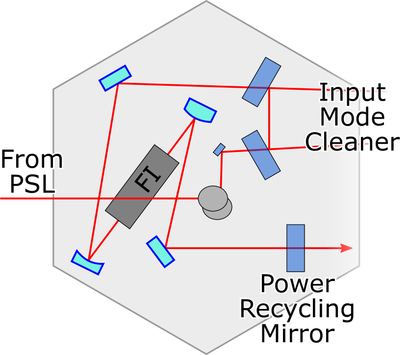
As shown in Fig. 1, the four optics suspended by the HAUX are all located on a single Advanced LIGO seismic isolation table, after the input mode cleaner (IMC) and before injection into the power-recycling cavity (PRC) of the main interferometer. The conceptual structure of the HAUX suspension chain has been based on the need of both precisely controlling the alignment of the input beam with respect to the main interferometer, and preserving the noise performance of the Input Optic Subsystem. In particular, the frequency and pointing noise introduced by the HAUX is generally required to be at least a factor below the noise at the output of the IMC.
Noise in the displacement x along the optical axis of a reflecting optic causes a variation of the total optical path and appears as frequency noise in the beam downstream of the optic. In addition, rotational noise of the optic around the horizontal or vertical axis orthogonal to the optical axis (referred to as pitch and yaw, respectively) directly couples into beam pointing noise (for a flat mirror).
Based on IMC requirements Mueller (2005), assuming that the four mirrors experience uncorrelated noise and conservatively neglecting the effect of non-normal angle of incidence, for a single suspension this translates into a requirement on the residual displacement noise of
| (1) | ||||
and on the residual rotational noise expressed as
| (2) |
These requirements are valid above , which is the lower limit of the Advanced LIGO measurement band.
In general, one degree of freedom of a single stage mechanical suspension can be modeled (under ideal conditions) as a harmonic oscillator with a natural resonant frequency . For frequencies above resonance, the displacement response of the suspended mass to external forces quickly approaches that of a free mass, decaying as . The response to motion of the suspension point shows a similar decay with frequency and goes as . The level of isolation at a given frequency can thus be controlled by an appropriate choice of .
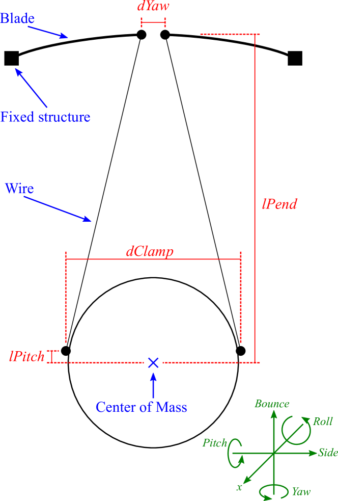
Considering the expected performance of the Advanced LIGO seismic isolation stack on which the HAUX are mountedMatichard et al. (2015), and even accounting for a safety factor, the HAUX requirements can be easily fulfilled by providing a single stage of isolation for x, pitch and yaw, as long as the resonance frequency in each degree of freedom is kept below a few Hz. Figure 2 shows a schematic representation of the configuration chosen for the HAUX suspensions, together with the geometrical parameters relevant to their performance. The optic is suspended from two wires, one on either side, which come close together at the upper suspension point; to a first approximation the resonant frequency of x is controlled by the length of the suspension wires (lPend), that of yaw is controlled by the horizontal separations of the upper (dYaw) and lower (dClamp) wire attachment points and that of pitch is controlled by the height of the lower attachment points above the optic’s center of mass (lPitch).
Below the Advanced LIGO measurement band, from o , the overall motion of the optic in pitch and yaw must be limited to RMS for the alignment sensing and control subsystem to be able to maintain the interferometer close to its ideal working point. This requires the amplitude of motion at the resonant frequencies to be limited, which is accomplished via active damping using a set of four sensor-actuators described in Section III.
An additional requirement for the HAUX is that the remaining three degrees of freedom of the optic must each have at least a single stage of isolation from the motion of the table, with a resonant frequency below . This requirement is met by hanging the two suspension wires from two blade springs: the common or differential motion of the blade’s tip allow for the optic to rotate around the optical axis (roll), swing orthogonal to it (side) or move along the vertical axis (bounce). Again, adjusting the geometrical and mechanical parameters allows controlling the resonance of these three degrees of freedom.
While it is clear that this geometry arrangement provides all the physical parameters needed to adjust the resonances to desired values, calculating the final transfer functions is not straightforward; the intuitive picture of independent harmonic oscillators acting along the different degrees of freedom is useful to understand how the various resonant frequencies can be controlled, but is not accurate; in reality, x and pitch, as well as roll and side, are degrees of freedom of double oscillator systems, and each pair combine to form two normal modes. In addition, the longitudinal and bending stiffness of the wires have a non-negligible effect on the resonances of some of the modesTorrie (2000). To calculate the values of the geometrical parameters needed to obtain the desired resonant frequency for each mode we used a semi-analytical model implemented as a Mathematica packageBarton , which accounts for all these effects. We also used the finite element analysis software COMSOL Multiphysics to model the blade springs and to obtain the desired vertical spring constant. The value of the parameters and the modeled resonant frequencies are reported in Tables 1 and 2. Note that, since precise matching of pre-determined resonance frequency values was not a requirement, no mechanism has been incorporated in the HAUX design to compensate for machining and assembly tolerances and to fine-tune the resonance frequency values.
| Parameter | Design value (mm) |
|---|---|
| dYaw | 15.7 |
| dClamp | 100.3 |
| lPitch | 1.0 |
| lPend | 259.3 |
| Mode | Modeled f0 (Hz) | Measured f0 (Hz) |
|---|---|---|
| x/pitch 1 | 0.98 | 0.95 |
| x/pitch 2 | 1.12 | 1.04 |
| yaw | 0.76 | 0.80 |
| bounce | 7.19 | 6.14 |
| side/roll 1 | 1.00 | 1.00 |
| side/roll 2 | 10.63 | 8.97 |
III Mechanical design
The final HAUX mechanical design, in addition to accommodating the suspensions chain described in the the previous section, had to satisfy a number of functional demands:
-
•
being vacuum compatible at the particularly stringent level required for Advanced LIGO, which imposes restrictions not only on the total outgassing, but also on the molecular species being outgassed;
-
•
being able to accommodate diameter mirrors with a clear aperture of at least , for horizontal angles of incidence up to ;
-
•
providing active control of the optics in x, pitch and yaw, and passive damping for all other degrees of freedom;
-
•
being equipped with safety stoppers to protect the optic in case of unexpected shaking or a wire failure, and to allow the optic to be clamped in place when needed;
-
•
allowing for fine tuning the optic working position in pitch to within , so as to mechanically remove any large offset from the active control system;
-
•
having the lowest structural resonance above about , to avoid interfering with the seismic-isolation table’s active control system;
-
•
last but not least, being as compact and simple as possible.
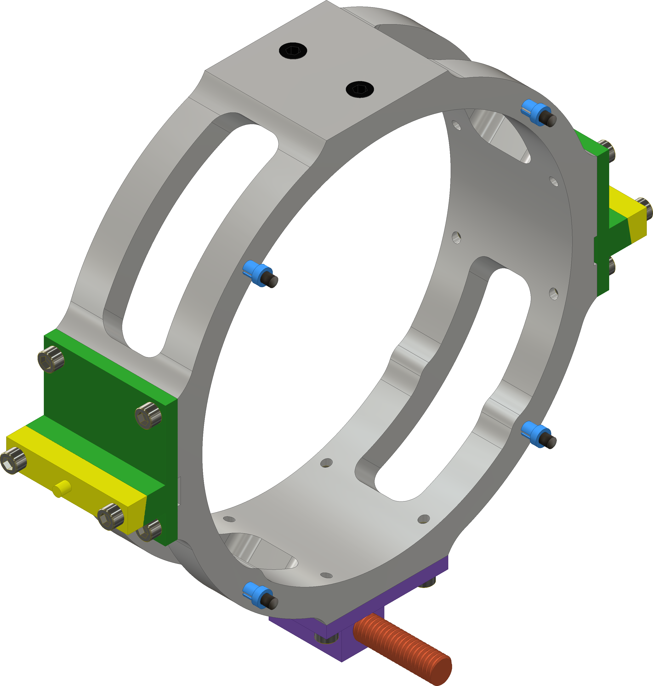
Assembly and maintenance of the suspensions and suspended optics is made more convenient by installing the diameter, thick optic in a lightweight aluminum holder, shown in Fig. 3 (top). In this way, attachment clamps and actuation magnets can be attached to the holder rather than directly glued to the optic, allowing for easy replacement of the mirror with minimal disassembly of the suspension. The optic is held in position by a pair of PEEK set screws that push it from the top against four raised contact points distributed on the front and back of the holder, at from the bottom. A wire clamp provided with an array of pre-machined vertical grooves is attached on either sides of the aluminum holder. The vertical grooves help fix the position of the wire and avoid over-squeezing; the array is necessary to be able to accommodate for the tolerance in the physical dimension of the different optics by selecting the suspension point closer to the center of mass. The optic holder has a fine-threaded horizontal through hole at the bottom that allows for a copper rod to be screwed back and forth to move the center of mass of the assembly by small amounts and adjust the static pitch of the optic.
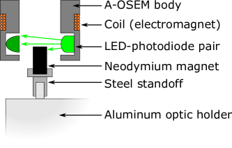
Four magnets are magnetically attached to four steel sleeves, which are press-fitted over matching posts arranged in a square pattern on the back of the holder. The magnets work together with the sensing/actuation units called AOSEMs Carbone et al. (2012). As shown in Fig. 4, an AOSEM is a combination of an electromagnetic actuator and a shadow sensor, in turn comprised of a LED and a photodetector. The AOSEM is attached to the structure of the suspension in such a way that the magnet is coaxial with the coil and partially shields the photodetector from the light coming from the LED. As the magnet moves back and forth, the amount of light reaching the photodetector changes and a position readout can be obtained. At the same time, a current can be run through the coil, creating a magnetic field and a force on the magnet. By suitable linear combinations of the readout of the four AOSEMs, signals for x, pitch and yaw can be obtained (three AOSEMs would be sufficient, but a fourth one has been introduced for redundancy, calibration and symmetry purposes).
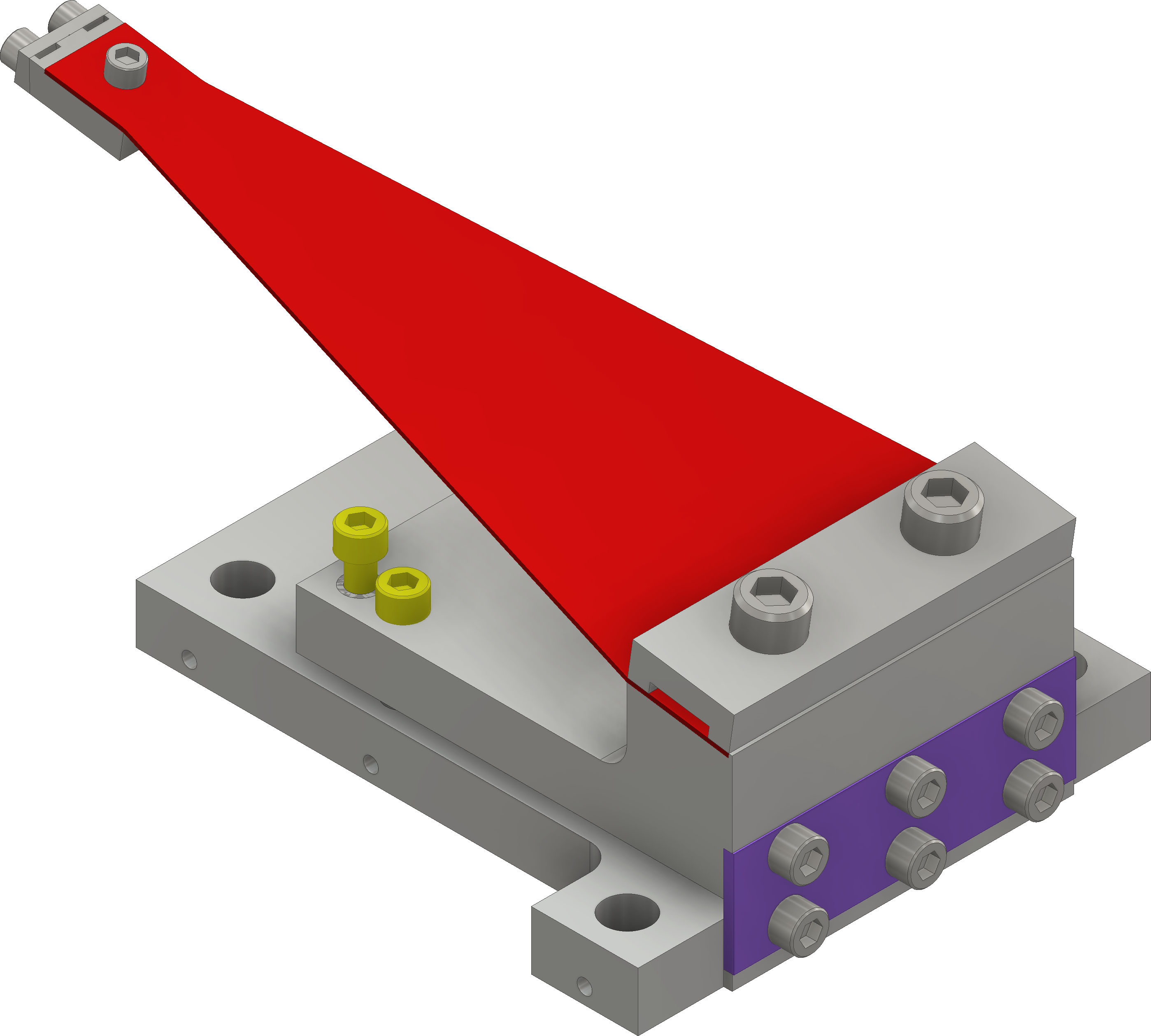
Two long, diameter steel music wires run from the bottom clamps to smaller, single-groove clamps at the tips of the spring blades, shown in Fig. 3 (bottom). The width profile of the monolithic, thick stainless steel blades is comprised of three sections: a wide, long flat tip attached to the wire clamp, a long tapered section that is free to flex and a wide, long section clamped to an adjustable blade support. The variable width of the tapered section allows for the stress to be equally distributed along the blade when the tip is loadedRobertson (2010). The support has a flexible joint and a system of push-pull screws that provide fine control of the departure angle of the blade, so that the working point of the tip can be made to be horizontal under load and, for small angles, oscillate only in the vertical direction. According to an analytical study and a finite-element model, the resulting spring constant is and the maximum stress under load is approximately , less than 50% of the yield strength of stainless steel.
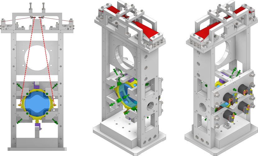
Figure 5 shows a 3D model of an assembled HAUX suspension. The main structure, made of aluminum to reduce weight, fits in an envelope of dimensions () and weighs approximately . It consists of a base, two side walls, two horizontal bars each supporting two AOSEMs, a stiffening slab connecting the two walls and a top slab to which the blade supports are attached (using slotted holes to allow for precise adjustment during assembly). From the structures surrounding the optic, a set of 14 soft-tip screws protrude towards the aluminum holder and serve the purpose of safety stop and clamping devices in case of need. Two pairs of neodymium magnets are mounted in aluminum casings directly above and below the optic holder, and provide passive damping via eddy currents. The magnets are anti-parallel, so as to minimize the field far from the suspension, and their distance from the holder can be adjusted from to about to obtain the desired level of damping. It should be noted that, although the damping is intended to mainly affect the degrees of freedom not actively controlled by the AOSEMs, this arrangement of magnets has some damping effect also on x, pitch and, much less, yaw.
IV Performance
The final HAUX prototype, as well as the production units, have been tested for both compliance with the requirements and quality of manufacturing Ciani (2011, 2013a, 2013b). The following subsections highlight the most important tests; when there are no significant differences between the various units, in the interest of clarity and space only a representative subset of results is presented.
Absolute calibration of most of these measurement involves independent calibration of a variety of software and hardware interfaces which are part of the Advanced LIGO control infrastructure, and not directly related to the HAUX design or their performance. Such calibration was often not available at the time the measurement were taken. For this reason, data are presented either in arbitrary units, or with a nominal calibration, depending on the case. Once the suspensions have been installed in the interferometer and the final components were available, the calibration of the entire chain, from software control interface to mirror response, has been verified to within 15% from the nominal value Feldbaum .
IV.1 Pitch and yaw pointing range
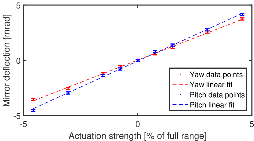
The mechanical limit to pitch and yaw rotation of the optic is set by the position of the safety stops, which can be adjusted to accommodate a range well beyond . The practical limit is then set by the available current to the coils, by the force per unit current that the AOSEMs can exert, with the magnets in use, and by the rotational stiffness of pitch and yaw, which with the design values for dYaw, dClamp and lPitch is of the order of for both degrees of freedom. The target dynamic range of can thus by obtained with a current of , or the maximum range can be reduced improving noise and resolution, depending on the design of the current driver. The linearity of the actuation in the range of interest is also important. Figure 6 shows the rotation of the optic measured using an optical lever for one of the production units, for various values of the commanded actuation.
IV.2 Resonant frequencies and transfer functions
The measured resonant frequencies for all six degrees of freedom are reported in Table 2 alongside the modeled values. These measurements were performed using the final prototype suspension built; however, the other eight production units assembled and installed in the Advanced LIGO detectors exhibit very similar values. It is apparent that there is a systematic tendency of the measured frequencies to be lower than the modeled ones. For the degrees of freedom dominated by the blades spring motion this is expected, as the blades had been independently tested before installation, and found to be softer than originally modeled (probably because of slightly different physical properties of the material used). For the other degrees of freedom the origin of the discrepancy has not been identified. A study of the suspension computer model has shown that a number of realistic machining and assembly tolerances, as well as material property variations, can combine in several ways to explain the observed values. However, this has not been further investigated, since it was of no particular interest in the context of Advanced LIGO where lower resonant frequencies are actually an advantage.
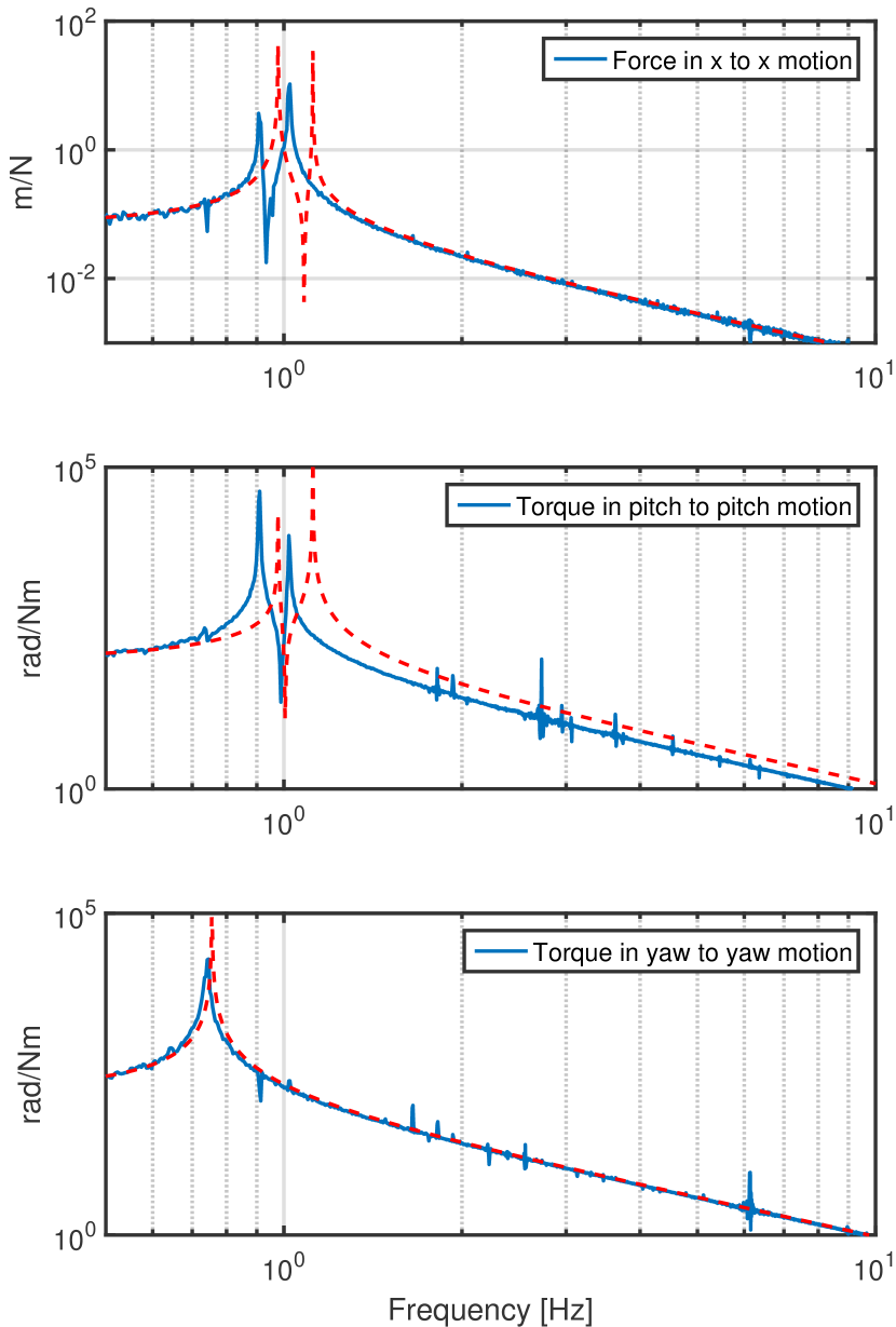
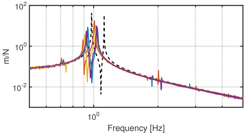
With the exception of the decrease in the resonant frequencies discussed above, the measured transfer functions agree very well with the model. As an example, Fig. 7 shows a subset of transfer functions from force (or torque) to displacement (or rotation) of the optic for one particular production unit labeled H1-IM3. Again, all the assembled and tested units show comparable results, as exemplified in Fig. 8, which shows the force to motion in the x degree of freedom transfer function, measured for 4 different units at the LIGO Hanford Observatory. Given that the HAUXs do not incorporate any mechanism to fine-tune the resonances of the as-built units, the agreement is very satisfactory, and compatible with expected machining and assembly tolerances.
It should be pointed out that the main goal of the suspensions is that of isolating the motion of the optic from that of the suspension point, making the transfer functions shown here not be the ones we are most directly interested in. However, they can be measured more easily and accurately than transfer functions from motion of the suspension to motion of the optics, and being dependent on the same parameters, they provide an equally valid verification of the suspension performance and agreement with the model.
IV.3 Active and passive damping
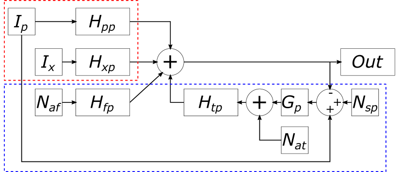
To estimate the noise performance and check compliance with the requirements during the design phase, we developed a noise model for each of the three actively controlled degrees of freedom (which are also the ones that most affect beam jitter and phase noise). As an example, Fig. 9 shows a schematic of the noise model developed for the pitch degree of freedom. The symbols are explained in Table 3.
| Symbol | Explanation |
|---|---|
| , | transfer functions from x and pitch motion of the platform, respectively, to pitch motion fo the optic |
| , | transfer functions from force and torque, respectively, to pitch motion fo the optic |
| , | pitch and x motion of the platform |
| , | actuation force and torque noise, respectively |
| pitch sensing noise | |
| feedback loop gain |
The top left part of the diagram represents the direct effect of motion of the suspension structure, in both pitch and x, on optic pitch motion. The lower part represents the contribution of the AOSEMs: the differential pitch readout between optic and suspension structure, affected by sensing noise, is conditioned by the feedback loop gain to obtain the pitch torque actuation signal. This, together with torque and force actuation noise, affects the optic pitch through the relevant transfer functions. Although force and torque noise originating from the AOSEMs are not statistically independent, the correlation is small and we treated them as such for simplicity.
Solving the model for the noise in pitch yields:
| (3) |
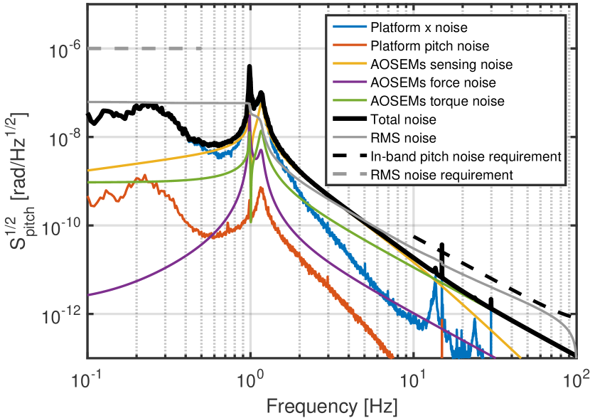
The various contributions to the final pitch noise, computed from input noise measured separately and transfer functions calculated from the Mathematica model, are plotted in Fig. 10. Here is a double-pole low pass filter; although this filter is not intended to be the final filter used in Advanced LIGO, it demonstrates that even this simple design is sufficient to meet requirements.
There are no specific requirements for the level of damping provided by the eddy current dampers; however, for non-cavity suspensions in Advanced LIGO it is generally considered adequate to obtain a quality factor, Q, somewhere between and to prevent the amplitude of motion of the uncontrolled degrees of freedom to grow too big. We designed the eddy current dampers to be adjustable, so that their effect could be varied over a wide range of values. Table 4 shows the reduction of Q in the three relevant degrees of freedom, measured by observing the rate of decay of oscillations, for the nominal placement of the magnets, away from the optic holder. As already mentioned at the end of Section III, the eddy current dampers also damp the actively controlled degrees of freedom, mostly x and pitch. This is not a problem in Advanced LIGO, because the resulting Q is still higher than the value targeted by the active control.
| DoF | Q, undamped | Q, damped |
|---|---|---|
| side/roll 1 | p m 1000 | p m 2 |
| side/roll 2 | p m 25 | p m 3 |
| bounce | p m 20 | p m 3 |
IV.4 Structural resonances
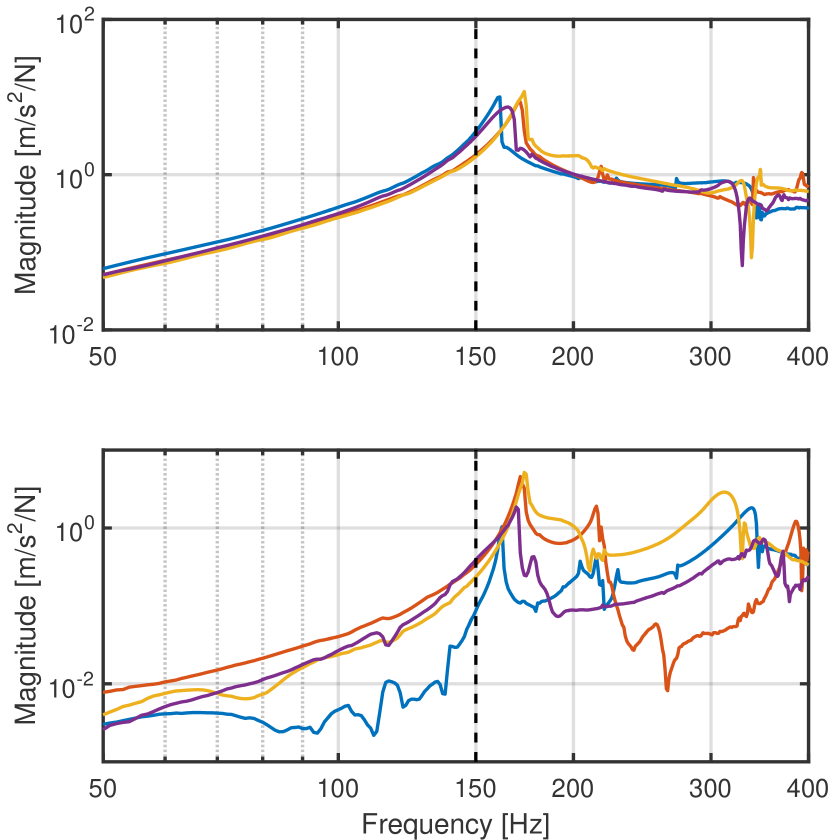
The mechanical resonances of the structure depend on the rigidity of the structure itself, and on to what and how the structure is clamped. Using a commercial system from Brüel&Kjær, we have measured each set of HAUX structural resonances when they are installed and clamped in their final position on the Advanced LIGO optical tablesJeff Kissel ; Stuart Aston . As an example, Fig. 11 shows the measurements taken for all 4 units installed at the Hanford Observatory. We found the measurements to be very consistent among different suspensions and to meet the requirement that the lower resonance be above 150 Hz, with the only exception of a unit installed at the Livingston Observatory; this non-compliance, probably due to a manufacturing issue, does not appear to have any significant impact on the performance of the ISI platforms, but it is nevertheless scheduled to be further investigated when interferometer operations allow.
V Conclusions
We have presented the design rationale and implementation of a compact single stage suspension for diameter optics. The suspension provides isolation in all degrees of freedom, with resonant frequencies around for all but the bounce and roll modes, which are below . The suspension has active control for the three most critical degrees of freedom of the optic, and passive damping for the remaining three. The design incorporates a number of expedients to make installation/replacement and initial alignment of the optics more convenient. The suspension design meets the requirements for suspending out-of-cavity optics in the Advanced LIGO Input Optics chain, and is versatile enough to be used in other precision optic experiments.
Acknowledgements.
The work presented in this paper has been supported by NSF grants PHY-0855313 and PHY-0969935, and by a subcontract stipulated with the LIGO Laboratory.References
- Abbott et al. (2016) B. P. Abbott, R. Abbott, T. D. Abbott, M. R. Abernathy, F. Acernese, K. Ackley, C. Adams, T. Adams, P. Addesso, R. X. Adhikari, V. B. Adya, C. Affeldt, M. Agathos, K. Agatsuma, N. Aggarwal, O. D. Aguiar, L. Aiello, A. Ain, P. Ajith, B. Allen, A. Allocca, P. A. Altin, S. B. Anderson, W. G. Anderson, K. Arai, M. A. Arain, M. C. Araya, C. C. Arceneaux, J. S. Areeda, N. Arnaud, K. G. Arun, S. Ascenzi, G. Ashton, M. Ast, S. M. Aston, P. Astone, P. Aufmuth, C. Aulbert, S. Babak, P. Bacon, M. K. M. Bader, P. T. Baker, F. Baldaccini, G. Ballardin, S. W. Ballmer, J. C. Barayoga, S. E. Barclay, B. C. Barish, D. Barker, F. Barone, B. Barr, L. Barsotti, M. Barsuglia, D. Barta, J. Bartlett, M. A. Barton, I. Bartos, R. Bassiri, A. Basti, J. C. Batch, C. Baune, V. Bavigadda, M. Bazzan, B. Behnke, M. Bejger, C. Belczynski, A. S. Bell, C. J. Bell, B. K. Berger, J. Bergman, G. Bergmann, C. P. L. Berry, D. Bersanetti, A. Bertolini, J. Betzwieser, S. Bhagwat, R. Bhandare, I. A. Bilenko, G. Billingsley, J. Birch, R. Birney, O. Birnholtz, S. Biscans, A. Bisht, M. Bitossi, C. Biwer, M. A. Bizouard, J. K. Blackburn, C. D. Blair, D. G. Blair, R. M. Blair, S. Bloemen, O. Bock, T. P. Bodiya, M. Boer, G. Bogaert, C. Bogan, A. Bohe, P. Bojtos, C. Bond, F. Bondu, R. Bonnand, B. A. Boom, R. Bork, V. Boschi, S. Bose, Y. Bouffanais, A. Bozzi, C. Bradaschia, P. R. Brady, V. B. Braginsky, M. Branchesi, J. E. Brau, T. Briant, A. Brillet, M. Brinkmann, V. Brisson, P. Brockill, A. F. Brooks, D. A. Brown, D. D. Brown, N. M. Brown, C. C. Buchanan, A. Buikema, T. Bulik, H. J. Bulten, A. Buonanno, D. Buskulic, C. Buy, R. L. Byer, M. Cabero, L. Cadonati, G. Cagnoli, C. Cahillane, J. C. Bustillo, T. Callister, E. Calloni, J. B. Camp, K. C. Cannon, J. Cao, C. D. Capano, E. Capocasa, F. Carbognani, S. Caride, J. C. Diaz, C. Casentini, S. Caudill, M. Cavaglià, F. Cavalier, R. Cavalieri, G. Cella, C. B. Cepeda, L. C. Baiardi, G. Cerretani, E. Cesarini, R. Chakraborty, T. Chalermsongsak, S. J. Chamberlin, M. Chan, S. Chao, P. Charlton, E. Chassande-Mottin, H. Y. Chen, Y. Chen, C. Cheng, A. Chincarini, A. Chiummo, H. S. Cho, M. Cho, J. H. Chow, N. Christensen, Q. Chu, S. Chua, S. Chung, G. Ciani, F. Clara, J. A. Clark, F. Cleva, E. Coccia, P.-F. Cohadon, A. Colla, C. G. Collette, L. Cominsky, M. Constancio, A. Conte, L. Conti, D. Cook, T. R. Corbitt, N. Cornish, A. Corsi, S. Cortese, C. A. Costa, M. W. Coughlin, S. B. Coughlin, J.-P. Coulon, S. T. Countryman, P. Couvares, E. E. Cowan, D. M. Coward, M. J. Cowart, D. C. Coyne, R. Coyne, K. Craig, J. D. E. Creighton, T. D. Creighton, J. Cripe, S. G. Crowder, A. M. Cruise, A. Cumming, L. Cunningham, E. Cuoco, T. D. Canton, S. L. Danilishin, S. D’Antonio, K. Danzmann, N. S. Darman, C. F. D. S. Costa, V. Dattilo, I. Dave, H. P. Daveloza, M. Davier, G. S. Davies, E. J. Daw, R. Day, S. De, D. DeBra, G. Debreczeni, J. Degallaix, M. D. Laurentis, S. Deléglise, W. D. Pozzo, T. Denker, T. Dent, H. Dereli, V. Dergachev, R. T. DeRosa, R. D. Rosa, R. DeSalvo, S. Dhurandhar, M. C. Díaz, L. D. Fiore, M. D. Giovanni, A. D. Lieto, S. D. Pace, I. D. Palma, A. D. Virgilio, G. Dojcinoski, V. Dolique, F. Donovan, K. L. Dooley, S. Doravari, R. Douglas, T. P. Downes, M. Drago, R. W. P. Drever, J. C. Driggers, Z. Du, M. Ducrot, S. E. Dwyer, T. B. Edo, M. C. Edwards, A. Effler, H.-B. Eggenstein, P. Ehrens, J. Eichholz, S. S. Eikenberry, W. Engels, R. C. Essick, T. Etzel, M. Evans, T. M. Evans, R. Everett, M. Factourovich, V. Fafone, H. Fair, S. Fairhurst, X. Fan, Q. Fang, S. Farinon, B. Farr, W. M. Farr, M. Favata, M. Fays, H. Fehrmann, M. M. Fejer, D. Feldbaum, I. Ferrante, E. C. Ferreira, F. Ferrini, F. Fidecaro, L. S. Finn, I. Fiori, D. Fiorucci, R. P. Fisher, R. Flaminio, M. Fletcher, H. Fong, J.-D. Fournier, S. Franco, S. Frasca, F. Frasconi, M. Frede, Z. Frei, A. Freise, R. Frey, V. Frey, T. T. Fricke, P. Fritschel, V. V. Frolov, P. Fulda, M. Fyffe, H. A. G. Gabbard, J. R. Gair, L. Gammaitoni, S. G. Gaonkar, F. Garufi, A. Gatto, G. Gaur, N. Gehrels, G. Gemme, B. Gendre, E. Genin, A. Gennai, J. George, L. Gergely, V. Germain, A. Ghosh, A. Ghosh, S. Ghosh, J. A. Giaime, K. D. Giardina, A. Giazotto, K. Gill, A. Glaefke, J. R. Gleason, E. Goetz, R. Goetz, L. Gondan, G. González, J. M. G. Castro, A. Gopakumar, N. A. Gordon, M. L. Gorodetsky, S. E. Gossan, M. Gosselin, R. Gouaty, C. Graef, P. B. Graff, M. Granata, A. Grant, S. Gras, C. Gray, G. Greco, A. C. Green, R. J. S. Greenhalgh, P. Groot, H. Grote, S. Grunewald, G. M. Guidi, X. Guo, A. Gupta, M. K. Gupta, K. E. Gushwa, E. K. Gustafson, R. Gustafson, J. J. Hacker, B. R. Hall, E. D. Hall, G. Hammond, M. Haney, M. M. Hanke, J. Hanks, C. Hanna, M. D. Hannam, J. Hanson, T. Hardwick, J. Harms, G. M. Harry, I. W. Harry, M. J. Hart, M. T. Hartman, C.-J. Haster, K. Haughian, J. Healy, J. Heefner, A. Heidmann, M. C. Heintze, G. Heinzel, H. Heitmann, P. Hello, G. Hemming, M. Hendry, I. S. Heng, J. Hennig, A. W. Heptonstall, M. Heurs, S. Hild, D. Hoak, K. A. Hodge, D. Hofman, S. E. Hollitt, K. Holt, D. E. Holz, P. Hopkins, D. J. Hosken, J. Hough, E. A. Houston, E. J. Howell, Y. M. Hu, S. Huang, E. A. Huerta, D. Huet, B. Hughey, S. Husa, S. H. Huttner, T. Huynh-Dinh, A. Idrisy, N. Indik, D. R. Ingram, R. Inta, H. N. Isa, J.-M. Isac, M. Isi, G. Islas, T. Isogai, B. R. Iyer, K. Izumi, M. B. Jacobson, T. Jacqmin, H. Jang, K. Jani, P. Jaranowski, S. Jawahar, F. Jiménez-Forteza, W. W. Johnson, N. K. Johnson-McDaniel, D. I. Jones, R. Jones, R. J. G. Jonker, L. Ju, K. Haris, C. V. Kalaghatgi, V. Kalogera, S. Kandhasamy, G. Kang, J. B. Kanner, S. Karki, M. Kasprzack, E. Katsavounidis, W. Katzman, S. Kaufer, T. Kaur, K. Kawabe, F. Kawazoe, F. Kéfélian, M. S. Kehl, D. Keitel, D. B. Kelley, W. Kells, R. Kennedy, D. G. Keppel, J. S. Key, A. Khalaidovski, F. Y. Khalili, I. Khan, S. Khan, Z. Khan, E. A. Khazanov, N. Kijbunchoo, C. Kim, J. Kim, K. Kim, N.-G. Kim, N. Kim, Y.-M. Kim, E. J. King, P. J. King, D. L. Kinzel, J. S. Kissel, L. Kleybolte, S. Klimenko, S. M. Koehlenbeck, K. Kokeyama, S. Koley, V. Kondrashov, A. Kontos, S. Koranda, M. Korobko, W. Z. Korth, I. Kowalska, D. B. Kozak, V. Kringel, B. Krishnan, A. Królak, C. Krueger, G. Kuehn, P. Kumar, R. Kumar, L. Kuo, A. Kutynia, P. Kwee, B. D. Lackey, M. Landry, J. Lange, B. Lantz, P. D. Lasky, A. Lazzarini, C. Lazzaro, P. Leaci, S. Leavey, E. O. Lebigot, C. H. Lee, H. K. Lee, H. M. Lee, K. Lee, A. Lenon, M. Leonardi, J. R. Leong, N. Leroy, N. Letendre, Y. Levin, B. M. Levine, T. G. F. Li, A. Libson, T. B. Littenberg, N. A. Lockerbie, J. Logue, A. L. Lombardi, L. T. London, J. E. Lord, M. Lorenzini, V. Loriette, M. Lormand, G. Losurdo, J. D. Lough, C. O. Lousto, G. Lovelace, H. Lück, A. P. Lundgren, J. Luo, R. Lynch, Y. Ma, T. MacDonald, B. Machenschalk, M. MacInnis, D. M. Macleod, F. Magaña-Sandoval, R. M. Magee, M. Mageswaran, E. Majorana, I. Maksimovic, V. Malvezzi, N. Man, I. Mandel, V. Mandic, V. Mangano, G. L. Mansell, M. Manske, M. Mantovani, F. Marchesoni, F. Marion, S. Márka, Z. Márka, A. S. Markosyan, E. Maros, F. Martelli, L. Martellini, I. W. Martin, R. M. Martin, D. V. Martynov, J. N. Marx, K. Mason, A. Masserot, T. J. Massinger, M. Masso-Reid, F. Matichard, L. Matone, N. Mavalvala, N. Mazumder, G. Mazzolo, R. McCarthy, D. E. McClelland, S. McCormick, S. C. McGuire, G. McIntyre, J. McIver, D. J. McManus, S. T. McWilliams, D. Meacher, G. D. Meadors, J. Meidam, A. Melatos, G. Mendell, D. Mendoza-Gandara, R. A. Mercer, E. Merilh, M. Merzougui, S. Meshkov, C. Messenger, C. Messick, P. M. Meyers, F. Mezzani, H. Miao, C. Michel, H. Middleton, E. E. Mikhailov, L. Milano, J. Miller, M. Millhouse, Y. Minenkov, J. Ming, S. Mirshekari, C. Mishra, S. Mitra, V. P. Mitrofanov, G. Mitselmakher, R. Mittleman, A. Moggi, M. Mohan, S. R. P. Mohapatra, M. Montani, B. C. Moore, C. J. Moore, D. Moraru, G. Moreno, S. R. Morriss, K. Mossavi, B. Mours, C. M. Mow-Lowry, C. L. Mueller, G. Mueller, A. W. Muir, A. Mukherjee, D. Mukherjee, S. Mukherjee, N. Mukund, A. Mullavey, J. Munch, D. J. Murphy, P. G. Murray, A. Mytidis, I. Nardecchia, L. Naticchioni, R. K. Nayak, V. Necula, K. Nedkova, G. Nelemans, M. Neri, A. Neunzert, G. Newton, T. T. Nguyen, A. B. Nielsen, S. Nissanke, A. Nitz, F. Nocera, D. Nolting, M. E. N. Normandin, L. K. Nuttall, J. Oberling, E. Ochsner, J. O’Dell, E. Oelker, G. H. Ogin, J. J. Oh, S. H. Oh, F. Ohme, M. Oliver, P. Oppermann, R. J. Oram, B. O’Reilly, R. O’Shaughnessy, C. D. Ott, D. J. Ottaway, R. S. Ottens, H. Overmier, B. J. Owen, A. Pai, S. A. Pai, J. R. Palamos, O. Palashov, C. Palomba, A. Pal-Singh, H. Pan, Y. Pan, C. Pankow, F. Pannarale, B. C. Pant, F. Paoletti, A. Paoli, M. A. Papa, H. R. Paris, W. Parker, D. Pascucci, A. Pasqualetti, R. Passaquieti, D. Passuello, B. Patricelli, Z. Patrick, B. L. Pearlstone, M. Pedraza, R. Pedurand, L. Pekowsky, A. Pele, S. Penn, A. Perreca, H. P. Pfeiffer, M. Phelps, O. Piccinni, M. Pichot, M. Pickenpack, F. Piergiovanni, V. Pierro, G. Pillant, L. Pinard, I. M. Pinto, M. Pitkin, J. H. Poeld, R. Poggiani, P. Popolizio, A. Post, J. Powell, J. Prasad, V. Predoi, S. S. Premachandra, T. Prestegard, L. R. Price, M. Prijatelj, M. Principe, S. Privitera, R. Prix, G. A. Prodi, L. Prokhorov, O. Puncken, M. Punturo, P. Puppo, M. Pürrer, H. Qi, J. Qin, V. Quetschke, E. A. Quintero, R. Quitzow-James, F. J. Raab, D. S. Rabeling, H. Radkins, P. Raffai, S. Raja, M. Rakhmanov, C. R. Ramet, P. Rapagnani, V. Raymond, M. Razzano, V. Re, J. Read, C. M. Reed, T. Regimbau, L. Rei, S. Reid, D. H. Reitze, H. Rew, S. D. Reyes, F. Ricci, K. Riles, N. A. Robertson, R. Robie, F. Robinet, A. Rocchi, L. Rolland, J. G. Rollins, V. J. Roma, J. D. Romano, R. Romano, G. Romanov, J. H. Romie, D. Rosińska, S. Rowan, A. Rüdiger, P. Ruggi, K. Ryan, S. Sachdev, T. Sadecki, L. Sadeghian, L. Salconi, M. Saleem, F. Salemi, A. Samajdar, L. Sammut, L. M. Sampson, E. J. Sanchez, V. Sandberg, B. Sandeen, G. H. Sanders, J. R. Sanders, B. Sassolas, B. S. Sathyaprakash, P. R. Saulson, O. Sauter, R. L. Savage, A. Sawadsky, P. Schale, R. Schilling, J. Schmidt, P. Schmidt, R. Schnabel, R. M. S. Schofield, A. Schönbeck, E. Schreiber, D. Schuette, B. F. Schutz, J. Scott, S. M. Scott, D. Sellers, A. S. Sengupta, D. Sentenac, V. Sequino, A. Sergeev, G. Serna, Y. Setyawati, A. Sevigny, D. A. Shaddock, T. Shaffer, S. Shah, M. S. Shahriar, M. Shaltev, Z. Shao, B. Shapiro, P. Shawhan, A. Sheperd, D. H. Shoemaker, D. M. Shoemaker, K. Siellez, X. Siemens, D. Sigg, A. D. Silva, D. Simakov, A. Singer, L. P. Singer, A. Singh, R. Singh, A. Singhal, A. M. Sintes, B. J. J. Slagmolen, J. R. Smith, M. R. Smith, N. D. Smith, R. J. E. Smith, E. J. Son, B. Sorazu, F. Sorrentino, T. Souradeep, A. K. Srivastava, A. Staley, M. Steinke, J. Steinlechner, S. Steinlechner, D. Steinmeyer, B. C. Stephens, S. P. Stevenson, R. Stone, K. A. Strain, N. Straniero, G. Stratta, N. A. Strauss, S. Strigin, R. Sturani, A. L. Stuver, T. Z. Summerscales, L. Sun, P. J. Sutton, B. L. Swinkels, M. J. Szczepańczyk, M. Tacca, D. Talukder, D. B. Tanner, M. Tápai, S. P. Tarabrin, A. Taracchini, R. Taylor, T. Theeg, M. P. Thirugnanasambandam, E. G. Thomas, M. Thomas, P. Thomas, K. A. Thorne, K. S. Thorne, E. Thrane, S. Tiwari, V. Tiwari, K. V. Tokmakov, C. Tomlinson, M. Tonelli, C. V. Torres, C. I. Torrie, D. Töyrä, F. Travasso, G. Traylor, D. Trifirò, M. C. Tringali, L. Trozzo, M. Tse, M. Turconi, D. Tuyenbayev, D. Ugolini, C. S. Unnikrishnan, A. L. Urban, S. A. Usman, H. Vahlbruch, G. Vajente, G. Valdes, M. Vallisneri, N. van Bakel, M. van Beuzekom, J. F. J. van den Brand, C. V. D. Broeck, D. C. Vander-Hyde, L. van der Schaaf, J. V. van Heijningen, A. A. van Veggel, M. Vardaro, S. Vass, M. Vasúth, R. Vaulin, A. Vecchio, G. Vedovato, J. Veitch, P. J. Veitch, K. Venkateswara, D. Verkindt, F. Vetrano, A. Viceré, S. Vinciguerra, D. J. Vine, J.-Y. Vinet, S. Vitale, T. Vo, H. Vocca, C. Vorvick, D. Voss, W. D. Vousden, S. P. Vyatchanin, A. R. Wade, L. E. Wade, M. Wade, S. J. Waldman, M. Walker, L. Wallace, S. Walsh, G. Wang, H. Wang, M. Wang, X. Wang, Y. Wang, H. Ward, R. L. Ward, J. Warner, M. Was, B. Weaver, L.-W. Wei, M. Weinert, A. J. Weinstein, R. Weiss, T. Welborn, L. Wen, P. Weßels, T. Westphal, K. Wette, J. T. Whelan, S. E. Whitcomb, D. J. White, B. F. Whiting, K. Wiesner, C. Wilkinson, P. A. Willems, L. Williams, R. D. Williams, A. R. Williamson, J. L. Willis, B. Willke, M. H. Wimmer, L. Winkelmann, W. Winkler, C. C. Wipf, A. G. Wiseman, H. Wittel, G. Woan, J. Worden, J. L. Wright, G. Wu, J. Yablon, I. Yakushin, W. Yam, H. Yamamoto, C. C. Yancey, M. J. Yap, H. Yu, M. Yvert, A. Zadrożny, L. Zangrando, M. Zanolin, J.-P. Zendri, M. Zevin, F. Zhang, L. Zhang, M. Zhang, Y. Zhang, C. Zhao, M. Zhou, Z. Zhou, X. J. Zhu, M. E. Zucker, S. E. Zuraw, and J. Zweizig (LIGO Virgo scientific collaboration), “Observation of gravitational waves from a binary black hole merger,” Phys. Rev. Lett. 116, 061102 (2016), arXiv:1602.03837 [gr-qc] .
- Martynov et al. (2016) D. Martynov, E. Hall, B. Abbott, R. Abbott, T. Abbott, C. Adams, R. Adhikari, R. Anderson, S. Anderson, K. Arai, M. Arain, S. Aston, L. Austin, S. Ballmer, M. Barbet, D. Barker, B. Barr, L. Barsotti, J. Bartlett, M. Barton, I. Bartos, J. Batch, A. Bell, I. Belopolski, J. Bergman, J. Betzwieser, G. Billingsley, J. Birch, S. Biscans, C. Biwer, E. Black, C. Blair, C. Bogan, R. Bork, D. Bridges, A. Brooks, C. Celerier, G. Ciani, F. Clara, D. Cook, S. Countryman, M. Cowart, D. Coyne, A. Cumming, L. Cunningham, M. Damjanic, R. Dannenberg, K. Danzmann, C. D. S. Costa, E. Daw, D. DeBra, R. DeRosa, R. DeSalvo, K. Dooley, S. Doravari, J. Driggers, S. Dwyer, A. Effler, T. Etzel, M. Evans, T. Evans, M. Factourovich, H. Fair, D. Feldbaum, R. Fisher, S. Foley, M. Frede, P. Fritschel, V. Frolov, P. Fulda, M. Fyffe, V. Galdi, J. Giaime, K. Giardina, J. Gleason, R. Goetz, S. Gras, C. Gray, R. Greenhalgh, H. Grote, C. Guido, K. Gushwa, E. Gustafson, R. Gustafson, G. Hammond, J. Hanks, J. Hanson, T. Hardwick, G. Harry, J. Heefner, M. Heintze, A. Heptonstall, D. Hoak, J. Hough, A. Ivanov, K. Izumi, M. Jacobson, E. James, R. Jones, S. Kandhasamy, S. Karki, M. Kasprzack, S. Kaufer, K. Kawabe, W. Kells, N. Kijbunchoo, E. King, P. King, D. Kinzel, J. Kissel, K. Kokeyama, W. Korth, G. Kuehn, P. Kwee, M. Landry, B. Lantz, A. L. Roux, B. Levine, J. Lewis, V. Lhuillier, N. Lockerbie, M. Lormand, M. Lubinski, A. Lundgren, T. MacDonald, M. MacInnis, D. Macleod, M. Mageswaran, K. Mailand, S. Márka, Z. Márka, A. Markosyan, E. Maros, I. Martin, R. Martin, J. Marx, K. Mason, T. Massinger, F. Matichard, N. Mavalvala, R. McCarthy, D. McClelland, S. McCormick, G. McIntyre, J. McIver, E. Merilh, M. Meyer, P. Meyers, J. Miller, R. Mittleman, G. Moreno, C. Mueller, G. Mueller, A. Mullavey, J. Munch, L. Nuttall, J. Oberling, J. O’Dell, P. Oppermann, R. J. Oram, B. O’Reilly, C. Osthelder, D. Ottaway, H. Overmier, J. Palamos, H. Paris, W. Parker, Z. Patrick, A. Pele, S. Penn, M. Phelps, M. Pickenpack, V. Pierro, I. Pinto, J. Poeld, M. Principe, L. Prokhorov, O. Puncken, V. Quetschke, E. Quintero, F. Raab, H. Radkins, P. Raffai, C. Ramet, C. Reed, S. Reid, D. Reitze, N. Robertson, J. Rollins, V. Roma, J. Romie, S. Rowan, K. Ryan, T. Sadecki, E. Sanchez, V. Sandberg, V. Sannibale, R. Savage, R. Schofield, B. Schultz, P. Schwinberg, D. Sellers, A. Sevigny, D. Shaddock, Z. Shao, B. Shapiro, P. Shawhan, D. Shoemaker, D. Sigg, B. Slagmolen, J. Smith, M. Smith, N. Smith-Lefebvre, B. Sorazu, A. Staley, A. Stein, A. Stochino, K. Strain, R. Taylor, M. Thomas, P. Thomas, K. Thorne, E. Thrane, C. Torrie, G. Traylor, G. Vajente, G. Valdes, A. van Veggel, M. Vargas, A. Vecchio, P. Veitch, K. Venkateswara, T. Vo, C. Vorvick, S. Waldman, M. Walker, R. Ward, J. Warner, B. Weaver, R. Weiss, T. Welborn, P. Weßels, C. Wilkinson, P. Willems, L. Williams, B. Willke, L. Winkelmann, C. Wipf, J. Worden, G. Wu, H. Yamamoto, C. Yancey, H. Yu, L. Zhang, M. Zucker, and J. Zweizig, “Sensitivity of the advanced LIGO detectors at the beginning of gravitational wave astronomy,” Physical Review D 93 (2016), 10.1103/physrevd.93.112004.
- Mueller et al. (2016) C. L. Mueller, M. A. Arain, G. Ciani, R. T. DeRosa, A. Effler, D. Feldbaum, V. V. Frolov, P. Fulda, J. Gleason, M. Heintze, K. Kawabe, E. J. King, K. Kokeyama, W. Z. Korth, R. M. Martin, A. Mullavey, J. Peold, V. Quetschke, D. H. Reitze, D. B. Tanner, C. Vorvick, L. F. Williams, and G. Mueller, “The Advanced LIGO Input Optics,” Rev. Sci. Instrum. 87, 014502 (2016), arXiv:1601.05442 [physics.ins-det] .
- (4) “The LIGO Document Control Center (DCC) is an online repository of documents produced by members of LIGO and the LIGO Scientific Collaboration. It is accessible from any modern web browser at the url https://dcc.ligo.org.” .
- Ciani et al. (2016) G. Ciani, M. Arain, S. Aston, D. Feldbaum, P. Fulda, J. Gleason, M. Heintze, R. Martin, C. Mueller, D. M. Nanda Kumar, A. Pele, D. Reitze, P. Sainathan, D. Tanner, L. Williams, and G. Mueller, “HAM Auxiliary suspensions design and testing documentation,” Tech. Rep. LIGO-E1600169 (LIGO Document Control Center, 2016).
- Mueller (2005) G. Mueller, “Beam jitter coupling in advanced LIGO,” Opt. Express 13, 7118 (2005).
- Matichard et al. (2015) F. Matichard, B. Lantz, R. Mittleman, K. Mason, J. Kissel, B. Abbott, S. Biscans, J. McIver, R. Abbott, S. Abbott, E. Allwine, S. Barnum, J. Birch, C. Celerier, D. Clark, D. Coyne, D. DeBra, R. DeRosa, M. Evans, S. Foley, P. Fritschel, J. A. Giaime, C. Gray, G. Grabeel, J. Hanson, C. Hardham, M. Hillard, W. Hua, C. Kucharczyk, M. Landry, A. L. Roux, V. Lhuillier, D. Macleod, M. Macinnis, R. Mitchell, B. O’Reilly, D. Ottaway, H. Paris, A. Pele, M. Puma, H. Radkins, C. Ramet, M. Robinson, L. Ruet, P. Sarin, D. Shoemaker, A. Stein, J. Thomas, M. Vargas, K. Venkateswara, J. Warner, and S. Wen, “Seismic isolation of advanced LIGO: Review of strategy, instrumentation and performance,” Class. Quant. Grav. 32, 185003 (2015), arXiv:1502.06300 [physics.ins-det] .
- Torrie (2000) C. I. E. Torrie, Development of suspensions for the GEO 600 gravitational wave detector, Ph.D. thesis, University of Glasgow (2000).
- (9) M. Barton, “Mathematica pendulum modeling toolkit,” https://labcit.ligo.caltech.edu/ e2e/SUSmodels/.
- Carbone et al. (2012) L. Carbone, S. M. Aston, R. M. Cutler, A. Freise, J. Greenhalgh, J. Heefner, D. Hoyland, N. A. Lockerbie, D. Lodhia, N. A. Robertson, C. C. Speake, K. A. Strain, and A. Vecchio, “Sensors and actuators for the advanced LIGO mirror suspensions,” Class. Quantum Grav. 29, 115005 (2012).
- Robertson (2010) N. A. Robertson, “Design Notes for Production Blades for HAM Suspensions,” Tech. Rep. LIGO-T1000351 (LIGO Document Control Center, 2010).
- Ciani (2011) G. Ciani, “HAM Auxiliary Suspensions modeling and test results,” Tech. Rep. LIGO-T1000339 (LIGO Document Control Center, 2011).
- Ciani (2013a) G. Ciani, “ALIGO IO L1 HAM AUX Test Results,” Tech. Rep. LIGO-T1300396 (LIGO Document Control Center, 2013).
- Ciani (2013b) G. Ciani, “ALIGO IO H1 HAM AUX Test Results,” Tech. Rep. LIGO-T1300397 (LIGO Document Control Center, 2013).
- (15) D. Feldbaum, “Ligo livingston electronic logbook, entry 4689,” https://alog.ligo-la.caltech.edu/aLOG/index.php?callRep=4689.
- (16) A. P. Jeff Kissel, “Ligo hanford electronic logbook, entry 5652,” https://alog.ligo-wa.caltech.edu/aLOG/index.php?callRep=5652.
- (17) P. F. Stuart Aston, “Ligo livingston electronic logbook, entry 3948,” https://alog.ligo-la.caltech.edu/aLOG/index.php?callRep=3948.