Perfect Fingerprint Orientation Fields
by Locally Adaptive Global Models
Abstract
Fingerprint recognition is widely used for verification and identification in many commercial, governmental and forensic applications. The orientation field (OF) plays an important role at various processing stages in fingerprint recognition systems. OFs are used for image enhancement, fingerprint alignment, for fingerprint liveness detection, fingerprint alteration detection and fingerprint matching. In this paper, a novel approach is presented to globally model an OF combined with locally adaptive methods. We show that this model adapts perfectly to the ’true OF’ in the limit. This perfect OF is described by a small number of parameters with straightforward geometric interpretation. Applications are manifold: Quick expert marking of very poor quality (for instance latent) OFs, high fidelity low parameter OF compression and a direct road to ground truth OFs markings for large databases, say. In this contribution we describe an algorithm to perfectly estimate OF parameters automatically or semi-automatically, depending on image quality, and we establish the main underlying claim of high fidelity low parameter OF compression.
Keywords
Fingerprint recognition, orientation field estimation, orientation field models, orientation field compression, orientation field marking, latent fingerprint recognition, fingerprint image enhancement, fingerprint matching
1 Introduction
The orientation field (OF) is a crucial ingredient for most fingerprint recognition systems [1]. An OF is an image (or matrix) which encodes at each pixel of the fingerprint foreground [2] the orientation degrees (or in radians) of a tangent to the ridge and valley flow at location . Modelling and estimating OFs is a fundamental task for automatic processing of fingerprints.
We introduce a locally adaptive global model called the extended quadratic differential (XQD) model. We show that XQDs can model the OF of a fingerprint perfectly in the limit. The major advantage of the XQD model lies in its small number of parameters, each of which has a simple and obvious geometric meaning.
OFs have many important areas of application at various stages of processing fingerprints. In the following part of this section, we discuss some of the most relevant of these applications. The rest of this manuscript is organized as follows. In Section 2, we review related work from the literature for estimating, modelling and marking OFs of fingerprints. In Section 3, we describe the novel XQD model. In Section 4, we prove that the XQD model adapts perfectly to the OF of a real fingerprint in the limit. In Section 5, we present practical results for compressing real fingerprint OFs by XQD models. We conclude in Section 6 with a discussion and we point out topics for future work.
1.1 Image Enhancement
Most systems for fingerprint verification and identification are based on minutiae templates. Automatic extraction of minutiae from fingerprints can be a very challenging task for images of low and very low quality. Quality loss of fingerprint images acquired on optical scanners can occur if a finger is too dry, or too wet, or contains scars. Putting a finger with too much or too little pressure on sensor can have similar negative effects on the image quality.
Poor image quality can cause a minutiae extraction module to miss some true minutiae and to introduce some spurious minutiae. The goal of fingerprint image enhancement is to avoid these two types of errors by improving the image quality prior to minutiae extraction. The most effective approach for fingerprint image enhancement is contextual filtering and the most important type of local context is the OF.
For example, oriented diffusion filtering [3] uses only the OF to perform anisotropic smoothing along the ridge and valley flow. Curved regions [4] are computed based on the OF and first, they are used for estimating the local ridge frequency and subsequently, OF and ridge frequency estimates are joint inputs for curved Gabor filtering [4]. These two methods estimate the local context and perform filtering in the spatial domain. Alternatively, methods for contextual filtering of fingerprints can also operate in the Fourier domain , see e.g. methods proposed by Chikkerur et al.[5] and by Bartunek et al.[6]. A hybrid approach with processing steps in the spatial and Fourier domain has been suggested by Ghafoor et al.[7].
1.2 Liveness Detection
Software-based fingerprint liveness detection strives to classify an input fingerprint as belonging to one of two classes: An image of an alive, real finger or an image of a fake or spoof finger made from artificial material like wood glue, gelatine or silicone. Developing countermeasures against spoof attacks is a very active research area. Two methods apply the OF to compute invariant descriptors: For histograms of invariant gradients (HIG) [8], the gradient direction at each pixel is normalized relative to the local orientation. Convolution comparison patterns (CCP) [9] are obtained from small image patches. To that end, rotation-invariant patches are computed by locally rotating each window according to the local orientation at that pixel.
1.3 Alteration Detection
Fingerprint alteration is another type of presentation attack [10] in which the attacker has the goal of avoiding identification (e.g. attempting to not being found in a watchlist search during border crossing or not being identified in a forensic investigation). Altered Fingerprints often have a disturbed OF. Therefore it is not surprising that in recent comparisons of features for alteration detection [11], some of the most effective features are related to the OF. In a nutshell, DOFTS [12] and OFA [13] are based on the difference between an estimated OF and a smoother version of it, COH [3] relies on the coherence of gradients and SPDA [14] makes use of the fact that alterations tend to introduce additional singularities into a fingerprint.
1.4 Matching
Orientation descriptors have been proposed by Tico and Kuosmanen [15] for computing the similarity between two minutiae from two templates. These local similarities are aggregated into a global score which summarizes the similarity between both templates.
Improvements of fingerprint recognition performance have been observed by using differences between two aligned OFs for score revaluation [16]: First, two minutiae templates are matched and the output is a global similarity score and a minutiae pairing. Second, the corresponding OFs are aligned, based on the paired minutiae and, the similarity between the OFs is evaluated. On the one hand, if both OFs fit well together, the aligned OFs confirm the minutiae pairing and the global score is increased. On the other hand, if major discrepancies between the aligned OFs are observed, this is considered as an indication of a potential impostor recognition attempt and the score is decreased accordingly.
1.5 Alignment
OFs are used for fingerprint alignment (also known as registration), i.e. finding a global rotation and translation of one OF with respect to other which is obtained by optimizing a cost function [17]. Krish et al.[18] considered in their work the alignment of partial fingerprints from fingermarks to ’full’ fingerprints, so called ’rolled’ fingerprints which are acquired with the help of e.g. a police officer who rolls the finger of subject to capture the full surface from nail to nail. Similar to above described score revaluation [16], they found that OF alignment improves the recognition performance, in their case, the rank-1 identification rate.
1.6 Classification and Indexing
The goal of classification and indexing is to speed up fingerprint identification (1 to N comparisons, where N can be in the magnitude of millions for forensic databases, see Chapter 5 in [1]). For example, the class tented arch is observed in about 3% of all fingerprints [1]. Hence, if a query fingerprint belongs to the class tented arch, then the search space can reduced by 97%. The majority of approaches for classification and indexing relies on OFs, e.g. Cappelli et al.[22] proposed a method for fingerprint classification by directional image partitioning. A recent survey by Galar et al.[23] lists 128 references and most of them use the OF (or its singular points) for classification.
1.7 Synthetic Fingerprint Generation
The generation of artificial fingerprint images has the advantage that it is possible to create arbitrarily large databases for research purposes e.g. of a million or a billion fingerprints at virtually no cost and without legal constraints. Methods for producing synthetic fingerprints include [24, 25, 26, 27]. A detailed discussion of approaches for constructing and reconstructing fingerprint images can be found in [28].
All methods have in common that they require an OF for the image creation process. The methods by Cappelli et al. [24] and by Araque et al. [25] rely on the global OF model by Vizcaya and Gerhardt [29]. In contrast, the realistic fingerprint creator (RFC) [27] uses OF estimations by a combination of gradient-based and line sensor methods [30] from a database of real fingerprints.
1.8 Separation of Overlapping Fingerprints
During a forensic investigation, it can occur that traces at a crime scene are detected where two or more latent fingerprints overlap on a surface. The task is to separate these fingerprints, so that the separated single fingerprints can individually be utilized for identification. Several research groups have addressed this problem in their work, and the key to the solution are in each work the OFs, see e.g. [31, 32, 33].
2 Estimation, Modelling and Marking of Orientation Fields
Considering the importance of the OF, it is no surprise that a large body of literature is treating the topic of automatic OF estimation. A classic approach is to estimate the OF by some form of averaging (squared) image gradients (computed e.g. using the Sobel filter) or symmetry features, see e.g. [35, 36, 37, 38]. However, this works only for good quality images. Further approaches include complex 2D energy operators [39]. For dealing also with medium and low-quality fingerprint images, the line sensor method [30, 40] was developed which recently has been adapted to detect the oriented filaments in microscopy images [41]. A dictionary based method [42] has been proposed for estimating the OF in latent fingerprints. Many additional references can be found in [43, 30, 44] and Chapter 3 of [1].
2.1 Global Models
The zero-pole model has been introduced by Sherlock and Monro in 1993 [45]. The flow fields generated by the zero-pole model resemble in some generality OFs of fingerprints, however they deviate significantly from OFs of a real finger. Vizcaya and Gerhardt improved the simple zero-pole model in 1996 [29] by suggesting an additional nonlinear bending scheme to better fit the OF generated by their model to real OFs. A global model based on quadratic differentials (QD) has been proposed by Huckemann et al. in 2008 [43]. The zero-pole model is a special case of this more general model which has five geometrically interpretable parameters. The QD model better fits real OFs especially for the fingerprint of the type arch. Further global models include the work by Ram et al.[46] who apply Legendre polynomials for OF modelling.
2.2 Manually Marking of Orientation Fields
There are two main motivations for manually marking information in fingerprints. The first is the creation of ground truth information which can be used for evaluating the performance of human experts and algorithms regarding the estimation or extraction of the target information. And the second use case is the labeling for (semi)automated retrival of information such as the foreground region, singular points, orientations or minutiae for fingerprint images which are too difficult for automatic processing by current state-of-the-art automatic fingerprint identification systems (AFIS) software. Forensic examiners mark such information in latent fingerprints to identify suspects in criminal investigations. Advancements in latent fingerprint recognition have the goal of minimizing the time and effort required by human experts for successful identifications.
2.2.1 Evaluating Orientation Field Estimation Performance
In order to compare the performance of different OF estimation methods, 1782 orientations at specific locations in various fingerprints in have been manually marked by Gottschlich et al. in [30] with a focus on low-quality regions affected by noise. Cappelli et al.[47] addressed the problem of enhancing very low-quality fingerprints and suggested to manually mark the OFs used for contextual filtering. They proposed to mark local orientations, compute the Delaunay triangulation and interpolate the orientation at unmarked pixel locations inside a triangle from the marked orientations at the three vertices of triangle. A disadvantage of this approach is that a large number of small triangles is required to approximate the true orientation in highly curved regions around singular points. Cappelli et al.[48] and Turroni et al.[44] created a ground truth benchmark called FOE following the same marking strategy (10 good and 50 bad quality prints). They compared the OF estimation performance of several algorithms from literature on this benchmark. The FOE benchmark has recently also been used for evaluating the performance of methods which reconstruct OFs from minutiae [49]. In our work, OF compression results using the FOE benchmark are reported in Section 5. We note that XQD models can be used as an alternate interpolation method not suffering from the need of large numbers of support points at high curvature near singularities.
2.2.2 Latent Fingerprint Recognition
Latent fingerprint recognition is still considered to be a difficult problem. The level of noise for some fingermarks from crime scenes can be high and depending the surface from which fingermarks are lifted (or directly photographed), a complex background can make the recognition task far more difficult in comparison with the processing fingerprints captured by a fingerprint sensor. Typical first steps, among them fingerprint segmentation [2, 50] and OF estimation, are challenging. Recently, a novel image decomposition technique called DG3PD has been introduced which can better cope with these challenging images, see Figures 9 and 10 in [51].
The goal of fully automatic latent fingerprint identification has not yet been achieved. Even state-of-the-art commercial latent identification software fails for a considerable amount of images and information still has to be manually marked by forensic experts in these cases. E.g. in a work by Yoon et al.[52], information about the region-of-interest (ROI), the location of singular points and the orientation at some sparse locations is still assumed to be manually marked. In the light of these problems, a subordinate target is to minimize the time and effort required by a human experts and the XQD model proposed in our work approach can be instrumental in achieving this.
2.3 Compression of Orientation Fields and Fingerprint Images
Forensic and governmental databases can contain millions of fingerprint images. Storing large volumes of data efficiently is a key issue which can be addressed by image compression [53]. Thärnå et al.[54] suggested to utilize the OF for improving lossless fingerprint image compression. More specifically, they suggest to increase redundancy by scanning pixels along the orientation, instead of standard procedures like horizontal (row by row) or vertical scanning of images. Larkin and Fletcher [55] proposed a method for lossy fingerprint image compression by decomposing an image into four elemental images which are highly compressible. One of these four images, called the continuous phase, can be converted into an OF and vice versa. Both approaches by Thärnå et al.[54] and by Larkin and Fletcher [55] can profit from improvements of the OF compression by our XQD models. If in an application e.g. by a law enforcement agency, fingerprint images and their minutiae templates are stored together, an straightforward idea would be to reconstruct the OF from the minutiae template. However, a recent evaluation of OF reconstruction methods [49] showed that all existing methods have weaknesses, and especially in proximity to singular points, all methods tend to be very inaccurate. In an analogy, minutiae templates can viewed as a form of lossy fingerprint image compressions. A survey of methods for reconstructing fingerprint images from minutiae templates can be found in [28]. Recently, Shao et al. [56] studied fingerprint image compression by use of dictionaries of fingerprint image patches. An additional discussion of texture image compression can be found in Section 7.3 in [51]. The efficiency of XQD models for OF compression will be detailed in Sections 3.4 and 5.
3 XQD Models
Our methods for manually marking and automatically compressing fingerprint OFs are based on the quadratic differential (QD) model of Huckemann et al.[43]. Consequently, we shall outline that model first.
3.1 The Quadratic Differential Model
The basis of this model is given by a model for the arch type fingerprint. Adding given singular point coordinates, i.e., cores and delta, this can be generalized to model the other fingerprint types.
The OF of an arch type fingerprint is roughly controlled by two parameters: Given a Cartesian coordinate system in complex coordinates , the OF is linked to the following complex function
| (1) |
for and, otherwise, , as follows. The orientation angle at the coordinate can be obtained by
| (2) |
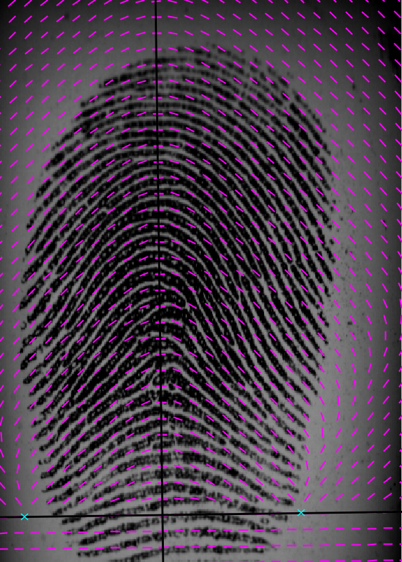
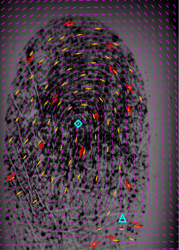
with the main branch of the argument of a complex number taking values in . The parameter controls the coordinates of two singularities and (2nd order zeroes of ) along the abscissa and is a factor controlling vertical stretching. In Fig. 1 a reasonable fit of the QD model to an arch type fingerprint is visualized where , , and the rotation and translation of the coordinate system have been adjusted.
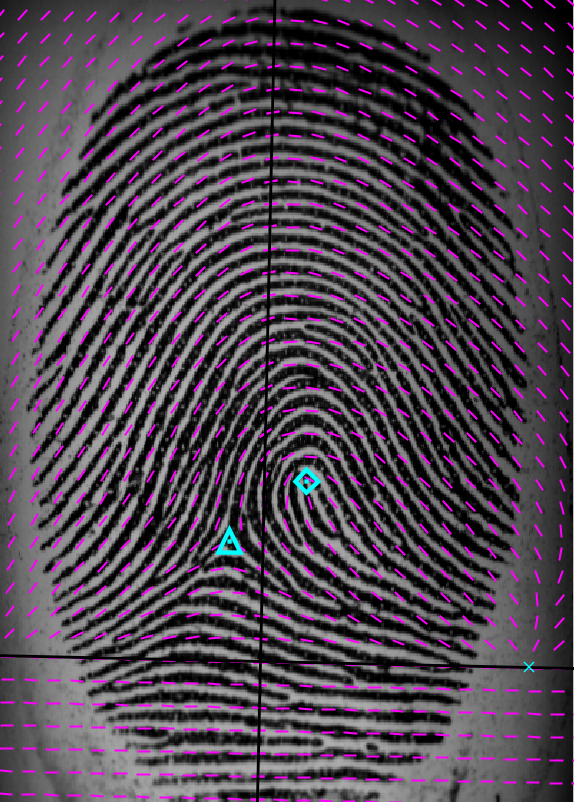
Fingerprints of other types (such as loops, double loops, and whorls) contain an equal number of deltas and cores — where a fingerprint cannot contain more than two deltas/cores; note that a whorl can be considered as a double loop in which the two cores agree or are of small distance. The following formula extends Eq. (1) to also model an OF of a loop type fingerprint of which core and delta coordinates are encoded by the complex and , respectively:
| (3) |
for and, otherwise, . Here denotes the complex conjugate of . An OF of a loop type fingerprint modeled by the QD model is visualized in Fig. 1. Similarly, a double loop with complex core coordinates and complex delta coordinates, is modeled by the following:
| (4) |
for and, otherwise, . For both models, Eq. (3) and Eq. (4), orientation angles are computed via Eq. (2).
For a more comprehensive treatment of the QD model, we refer the reader to [43] and the literature therein on geometric function theory; there the inverse of is considered giving the quadratic differential (QD)
the solution curves of having the orientations from Eq. (2). Then, in particular the “zeroes” of are in fact poles of the QD and “poles” of are zeroes of the QD.
3.2 Extended Quadratic Differential Model
As can be seen in Fig. 1, the QD model can be used to quite well approximate the general ridge flow using few parameters only. However, the reader quickly recognizes areas in which the model significantly deviates from the evident ground-truth ridge flow which is an unavoidable effect due to the fact that in the QD model has only few degrees of freedom. Consequently, we need to change or extend the model. In this paper, we propose to attach a variable number of local correction points to which we refer as anchor points thereby obtaining an extended quadratic differential (XQD) model. With these points the local OF modeled by a QD can be corrected to better match with the ridge flow of a fingerprint.
Anchor Points

An anchor point is a -tuple where is a two-dimensional coordinate, an orientation angle, and and are two postive numbers. More precisely, denotes a coordinate at which the orientation given by a QD model is to be corrected; denotes the orientation angle of the true field at which is to become the new orientation angle there; finally, and control how significantly the orientation correction influences the neighboring orientations around . Even more specifically, given the orientation angles of a QD (see Eq. (2)), a true orientation at an anchor point the new orientation angles at any coordinate is computed as
| (5) |
where denotes a correction angle. The correction angle is defined as
| (6) |
where denotes a function that assumes the value at and decays quickly to zero away from it. Here is the coordinate represented w.r.t. a coordinate system defined by (origin) and (rotation); specifically,
| (7) | ||||
For example can be a tent function as in Eq. (16) with . To obtain a higher degree of smoothness, in the applications we use the two-dimensional Gaussian
| (8) |
Multiple Anchor Points
Similarly, given the OF of a QD, the correction angle at can be defined recursively from a multiple number of anchor points as
| (9) | ||||
for and as in Eq. (6) for . This yields our final XQD model
| (10) |
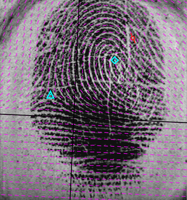
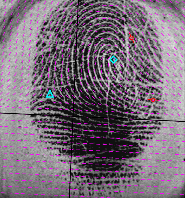
In Fig. 2 the effect of correcting a QD model’s OF using an increasing number of anchor points is visualized.
3.3 Manually Marking of Orientation Fields
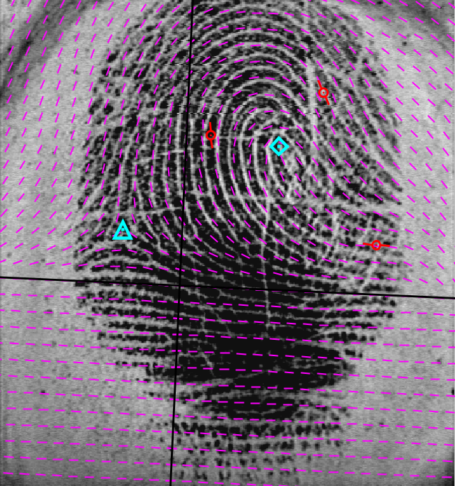
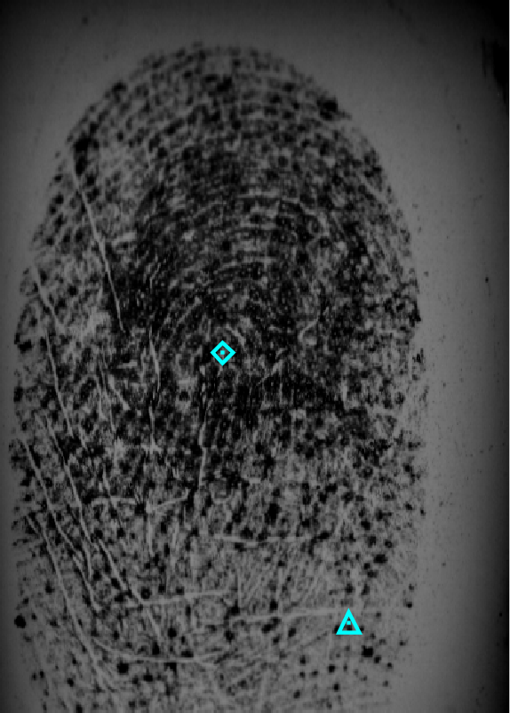
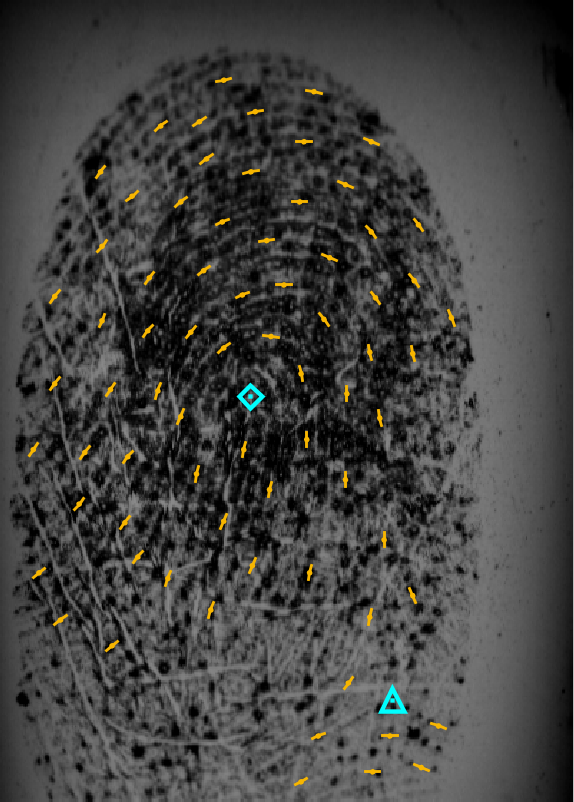
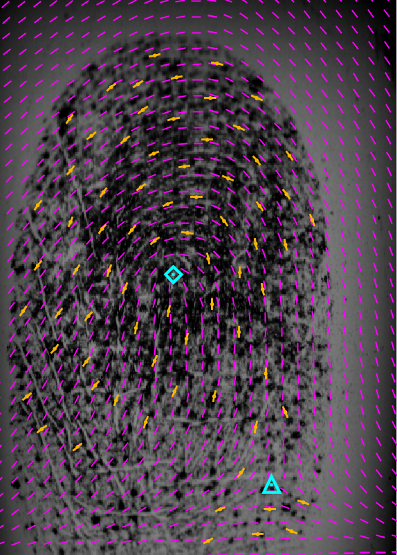
One important application of our XQD model is to manually mark semi-automatically a fingerprint’s OF by an expert. From the many choices of orders of tasks, by preliminary experiments, we found the following strategy useful, the steps of which are visualized in Fig. 3.
-
1.
Manually mark the position of all cores and deltas of the fingerprint (Fig. 3(a)).
-
2.
Manually mark an initial OF (possibly at sparse locations only, see Fig. 3(b)).
- 3.
-
4.
Successively insert anchor points to the XQD model further minimizing the objective function (Fig. 3(d)).
-
5.
The final XQD model agrees, within a preselected error bound, say, with the manually marked OF. This and other stopping strategies are discussed and illustrated in Section 5.
Given the OF of an XQD model, i.e., , and an initial OF , we can measure the deviation of the XQD model to the initial OF by the following objective function, which, depends on all parameters of the XQD model:
| (11) | |||||
We note that, if steps 1 and 2 have been performed manually by an expert, the remaining steps can be implemented to run (semi-)automatically by utilizing a steepest descent method applied to the objective function Eq. (11).
3.4 Compressing Orientation Fields
The key property of the XQD model is its ability to compactly represent, while having the power of arbitrarly well approximating, a fingerprint’s OF. More specifically, recall that we count a total of at most real parameters describing a QD model: the parameters and (see Eq. (1)) describing size and stretching, a two-fold parameter for translation, and one more parameter for rotation; further, a fingerprint can contain at most two cores and two deltas. As an XQD model is influenced by a variable number of anchor points each described by real parameters, an XQD model with anchor points consumes a total of at most
| (12) |
real parameters, where is the number of singular points.
Given an uncompressed OF, an XQD model can ideally be approximated automatically with a small number of anchor points to compress the field. In Fig. 3 a manually marked fingerprint (from FOE, here assuming no ground truth OF available) has been modeled by a XQD with anchor points. At this point we stress that the XQD model requires a reasonable estimation of the singular points — even if they lie outside of the fingerprint’s region of interest. Unfortunately, to date there is no method known that robustly estimates all singular points. Beyond that, however, we are able to automatically obtain an XQD model from an OF thereby obtaining an effective method for compressing OFs.
4 Perfectly Adapting Orientation Fields in the Limit
It is general consent that fingerprint OFs are smooth except for the singularities at cores and deltas (e.g. [1, Section 3.6]). In consequence, denoting with
the complex orientation of the true field at pixel location and denoting by
the complex orientation of a QD model at with the same cores and deltas we may assume that there is a Lipschitz constant such that
| (13) |
for all in the observation window, while of course
is unbound near the singularities.
For the following we assume that we have fit a QD model to a fingerprint’s OF with same singularities, such that we can assume (13) for
According to the algorithm introduced above, given an approximation to and a correction function , for our convergence considerations here we use not the one given by Eq. (6) but a tent function
| (16) |
for suitable , we first show that the next iterate
is closer to than the previous. Building on that we then propose an algorithm, theoretically assuring an asymptotically perfect adaption to the OF.
Lemma 4.1.
For fixed location and radius , with the Lipschitz constant from (13), the following hold:
-
(i)
whenever ,
-
(ii)
if for some and with then
-
(iii)
choosing we have
Proof.
The first assertion follows from construction. For the second set . Then
| (17) | |||||
Taking the maximum of the last expression over yields (ii).
(iii): With the choice for , setting , the right hand side of (17) attains its maximum at and the value at . ∎
Theorem 4.2.
With the algorithm of the following proof every fingerprint OF can be perfectly adapted in the limit, i.e.
Proof.
We detail one iteration step of the algorithm and then show its convergence. Suppose after the -st iteration, , we have an approximation with . Set and place a finite number of anchor points such that
covers the fingerprint area, here . Setting , define
and . In every step , due to (iii) (b) of the above Lemma, the approximation error within is below , everywhere else, due to (iii) (a), the error will still be bound by . According to (ii), the next iteration will change the error within to below . Since the mapping maps the interval to itself, after at most iterations, with some constant independent of , we have
Now suppose that the sequence would not converge to zero but to to . Then due to and pointwise monotonicity in iterates,
yielding a contradiction. This proves that every OF can be assymptotically perfectly adapted. ∎
5 Compression Results
Here we report compression results using the ten good quality OFs provided by [44] as ground truths. As detailed in Section 3.4, we have first manually marked singular points and afterwards automatically fit XQD models employing the following several optimization strategies. Stopping criteria and specific improvement steps in each iteration depend on the choice of to the main goal which can be:
-
•
As fast as possible (minimal runtime) in order to achieve a small deviation of the reconstructed OF from the ground truth.
-
•
As exact as possible (minimal deviation from the ground truth OF) where we allow e.g. at most anchor points.
-
•
As compressed as possible (minimal file size of the stored XQD)
-
•
As sparse as possible (minimal number of anchor points)
Note that in consequence of (12) the model’s sparsity relates directly to the compression rate: Minimizing the number of anchor points is equivalent to a aiming for high compression, see Table 1 and 2. At every iteration step several choices are possible. One may optimize speed by simply adding a few anchor points without optimizing all possible parameters (e.g. strategy S1). Alternatively, when accuracy is optimized (e.g. strategy S4), in every iteration step not only all present anchor points are optimized but as well the choice of singular points and the other parameters of the underlying QD model are reconsidered. Balancing the three main goals of speed, compression rate and accuracy of the reconstructed OF allows for a range of intermediate strategies (e.g. S2 and S3). Results for four example strategies using a grid spacing of 12 pixels for ground truth orientation locations are reported in Table 1.
6 Conclusion
In this work we have presented a semi-automatic tool based on a comprehensive XQD model for the orientation field of fingerprints, that achieves arbitrary precision at a very high compression rate in rather short time. A compression by a factor of , say, at an accuracy of a few degrees in a few seconds (see Table 1 and 2)
This semi-automatic tool can also be used for fast marking of orientation fields of fingerprints, be it for forensic application or in order to generate large orientation field benchmark databases. After labeling (or accepting the tool’s proposals) of singular points, location, orientation and scaling of a fingerprint image, a very sparse representation of the orientation field with arbitrary precision is fast and automatically built.
While in order to give a proof of concept, we have used the benchmark FOE dataset, in future work orientation field estimation methods (e.g. [4]) can be combined with our XQD model allowing for a ’next generation comprehensive low-dimensional fingerprint template’ consisting of minutiae plus segmentation (e.g. [2]) plus anchor points (XQD) plus at most 13 parameters (QD). One may even consider to place the anchor points at minutiae locations, then only their s need to be recorded. Additionally, ideal locations of anchor points – these give the deviation from a conformal QD model – deserve to be studied over large databases.
Acknowledgements
The authors gratefully acknowledge the support of the Felix-Bernstein-Institute for Mathematical Statistics in the Biosciences and the Niedersachsen Vorab of the Volkswagen Foundation. Stephan Huckemann expresses gratitude to the support by the SAMSI Forensics Workshop 2015/16.
References
- [1] D. Maltoni, D. Maio, A. K. Jain, and S. Prabhakar. Handbook of Fingerprint Recognition. Springer, London, U.K., 2009.
- [2] D.H. Thai, S. Huckemann, and C. Gottschlich. Filter design and performance evaluation for fingerprint image segmentation. PLoS ONE, 11(5):e0154160, May 2016.
- [3] C. Gottschlich and C.-B. Schönlieb. Oriented diffusion filtering for enhancing low-quality fingerprint images. IET Biometrics, 1(2):105–113, June 2012.
- [4] C. Gottschlich. Curved-region-based ridge frequency estimation and curved Gabor filters for fingerprint image enhancement. IEEE Transactions on Image Processing, 21(4):2220–2227, April 2012.
- [5] S. Chikkerur, A. Cartwright, and V. Govindaraju. Fingerprint image enhancement using STFT analysis. Pattern Recognition, 40(1):198–211, 2007.
- [6] J.S. Bartůněk, M. Nilsson, B. Sällberg, and I. Claesson. Adaptive fingerprint image enhancement with emphasis on preprocessing of data. IEEE Transactions on Image Processing, 22(2):644–656, February 2013.
- [7] M. Ghafoor, I.A. Taj, W. Ahmad, and N.M. Jafri. Efficient 2-fold contextual filtering approach for fingerprint enhancement. IET Image Processing, 8(7):417–425, July 2014.
- [8] C. Gottschlich, E. Marasco, A.Y. Yang, and B. Cukic. Fingerprint liveness detection based on histograms of invariant gradients. In Proc. IJCB, pages 1–7, Clearwater, FL, USA, September 2014.
- [9] C. Gottschlich. Convolution comparison pattern: An efficient local image descriptor for fingerprint liveness detection. PLoS ONE, 11(2):e0148552, February 2016.
- [10] C. Sousedik and C. Busch. Presentation attack detection methods for fingerprint recognition systems: a survey. IET Biometrics, 3(4):219–233, December 2014.
- [11] C. Gottschlich, A. Mikaelyan, M.A. Olsen, J. Bigun, and C. Busch. Improving fingerprint alteration detection. In Proc. ISPA, pages 85–88, Zagreb, Croatia, September 2015.
- [12] J. Bigun and A. Mikaelyan. Dense frequency maps by structure tensor and logarithmic scale space: application to forensic fingerprints. http://www.diva-portal.org/smash/get/diva2:810855/FULLTEXT01.pdf, 2015.
- [13] S. Yoon, J. Feng, and A.K. Jain. Altered fingerprints: Analysis and detection. IEEE Transactions on Pattern Analysis and Machine Intelligence, 34(3):451–464, March 2012.
- [14] J. Ellingsgaard, C. Sousedik, and C. Busch. Detecting fingerprint alterations by orientation field and minutiae orientation analysis. In Proc. IWBF, pages 1–6, Valletta, Malta, March 2014.
- [15] M. Tico and P. Kuosmanen. Fingerprint matching using an orientation-based minutia descriptor. IEEE Transactions on Pattern Analysis and Machine Intelligence, 25(8):1009–1014, August 2003.
- [16] C. Gottschlich. Fingerprint growth prediction, image preprocessing and multi-level judgment aggregation. PhD thesis, University of Goettingen, Goettingen, Germany, April 2010.
- [17] N. Yager and A. Amin. Evaluation of fingerprint orientation field registration algorithms. In Proc. ICPR, Cambridge, UK, August 2004.
- [18] R.P. Krish, J. Fierrez, D. Ramos, J. Ortega-Garcia, and J. Bigun. Pre-registration of latent fingerprints based on orientation field. IET Biometrics, 4(2):42–52, June 2015.
- [19] B. Tams. Absolute fingerprint pre-alignment in minutiae-based cryptosystems. In Proc. BIOSIG, pages 75–86, Darmstadt, Germany, September 2013.
- [20] B. Tams. Cryptanalysis of the Fuzzy Vault for Fingerprints: Vulnerabilities and Countermeasures. PhD thesis, University of Goettingen, Goettingen, Germany, December 2012.
- [21] B. Tams. Unlinkable minutiae-based fuzzy vault for multiple fingerprints. IET Biometrics, to appear, doi: 10.1049/iet-bmt.2014.0093.
- [22] R. Cappelli, A. Lumini, D. Maio, and D. Maltoni. Fingerprint classification by directional image partitioning. IEEE Transactions on Pattern Analysis and Machine Intelligence, 21(5):402–421, May 1999.
- [23] M. Galar et al. A survey of fingerprint classification part I: Taxonomies on feature extraction methods and learning models. Knowledge-Based Systems, 81:76–97, June 2015.
- [24] R. Cappelli, A. Erol, D. Maio, and D. Maltoni. Synthetic fingerprint-image generation. In Proc. 15th Int. Conf. Pattern Recogn. (ICPR), pages 3–7, Barcelona, Spain, September 2000.
- [25] J.L. Araque, M. Baena, B.E. Chalela, D. Navarro, and P.R. Vizcaya. Synthesis of fingerprint images. In Proc. 16th Int. Conf. Pattern Recogn. (ICPR), pages 422–425, 2002.
- [26] M. Kücken and C. Champod. Merkel cells and the individuality of friction ridge skin. Journal of Theoretical Biology, 317:229–237, 2013.
- [27] C. Imdahl, S. Huckemann, and C. Gottschlich. Towards generating realistic synthetic fingerprint images. In Proc. ISPA, pages 80–84, Zagreb, Croatia, September 2015.
- [28] C. Gottschlich and S. Huckemann. Separating the real from the synthetic: Minutiae histograms as fingerprints of fingerprints. IET Biometrics, 3(4):291–301, December 2014.
- [29] P. R. Vizcaya and L. A. Gerhardt. A nonlinear orientation model for global description of fingerprints. Pattern Recognition, 29(7):1221–1231, 1996.
- [30] C. Gottschlich, P. Mihăilescu, and A. Munk. Robust orientation field estimation and extrapolation using semilocal line sensors. IEEE Transactions on Information Forensics and Security, 4(4):802–811, December 2009.
- [31] K. Qian, M. Schott, W. Zheng, and J. Dittmann. Context-based approach of separating contactless captured high-resolution overlapped latent fingerprints. IET Biometrics, 3(2):101–112, June 2014.
- [32] J. Feng, Y. Shi, and J. Zhou. Robust and efficient algorithms for separating latent overlapped fingerprints. IEEE Transactions on Information Forensics and Security, 7(5):1498–1510, October 2012.
- [33] Q. Zhao and A.K. Jain. Model based separation of overlapping latent fingerprints. IEEE Transactions on Information Forensics and Security, 7(3):904–918, June 2012.
- [34] M. Hildebrandt and J. Dittmann. StirTraceV2.0: Enhanced benchmarking and tuning of printed fingerprint detection. IEEE Transactions on Information Forensics and Security, 10(4):833–848, April 2015.
- [35] J. Bigun and G.H. Granlund. Optimal orientation detection of linear symmetry. In Proc. ICCV, pages 433–438, London, UK, June 1987.
- [36] J. Bigun. Recognition of local symmetries in gray value images by harmonic functions. In Proc. ICPR, pages 345–347, Rome, Italy, November 1988.
- [37] A.M. Bazen and S.H. Gerez. Systematic methods for the computation of the directional fields and singular points of fingerprints. IEEE Transactions on Pattern Analysis and Machine Intelligence, 24(7):905–919, July 2002.
- [38] J. Bigun. Vision with direction. Springer, Berlin, Germany, 2006.
- [39] K.G. Larkin. Uniform estimation of orientation using local and nonlocal 2-D energy operators. Optics Express, 13(20):8097–8121, October 2005.
- [40] C. Gottschlich, P. Mihăilescu, and A. Munk. Robust orientation field estimation in fingerprint images with broken ridge lines. In Proc. ISPA, pages 529–533, Salzburg, Austria, September 2009.
- [41] B. Eltzner, C. Wollnik, C. Gottschlich, S. Huckemann, and F. Rehfeldt. The filament sensor for near real-time detection of cytoskeletal fiber structures. PLoS ONE, 10(5):e0126346, May 2015.
- [42] J. Feng, J. Zhou, and A.K. Jain. Orientation field estimation for latent fingerprint enhancement. IEEE Transactions on Pattern Analysis and Machine Intelligence, 35(4):925–940, April 2013.
- [43] S. Huckemann, T. Hotz, and A. Munk. Global models for the orientation field of fingerprints: an approach based on quadratic differentials. IEEE Transactions on Pattern Analysis and Machine Intelligence, 30(9):1507–1517, September 2008.
- [44] F. Turroni, D. Maltoni, R. Cappelli, and D. Maio. Improving fingerprint orientation extraction. IEEE Transactions on Information Forensics and Security, 6(3):1002–1013, September 2011.
- [45] B.G. Sherlock and D.M. Monro. A model for interpreting fingerprint topology. Pattern Recognition, 26(7):1047–1055, July 1993.
- [46] S. Ram, H. Bischof, and J. Birchbauer. Modelling fingerprint ridge orientation using Legendre polynomials. Pattern Recognition, 43(1):342–357, January 2010.
- [47] R. Cappelli, D. Maio, and D. Maltoni. Semi-automatic enhancement of very low quality fingerprints. In Proc. ISPA, pages 678–683, Salzburg, Austria, September 2009.
- [48] R. Cappelli, D. Maltoni, and F. Turroni. Benchmarking local orientation extraction in fingerprint recognition. In Proc. 20th Int. Conf. Pattern Recogn. (ICPR), pages 1144–1147, Istanbul, Turkey, August 2010.
- [49] L. Oehlmann, S. Huckemann, and C. Gottschlich. Performance evaluation of fingerprint orientation field reconstruction methods. In Proc. IWBF, pages 1–6, Gjovik, Norway, March 2015.
- [50] D.H. Thai and C. Gottschlich. Global variational method for fingerprint segmentation by three-part decomposition. IET Biometrics, 5(2):120–130, June 2016.
- [51] D.H. Thai and C. Gottschlich. Directional global three-part image decomposition. EURASIP Journal on Image and Video Processing, 2016(12):1–20, March 2016.
- [52] S. Yoon, J. Feng, and A.K. Jain. On latent fingerprint enhancement. In Proc. BTHI, pages 1–10, Orlando, FL, USA, April 2010.
- [53] D. Salomon. Data Compression. Springer, London, UK, fourth edition edition, 2007.
- [54] J. Thärnå, K. Nilsson, and J. Bigun. Orientation scanning to improve lossless compression of fingerprint images. In Proc. AVBPA, pages 343–350, Guildford, UK, June 2003.
- [55] K.G. Larkin and P.A. Fletcher. A coherent framework for fingerprint analysis: Are fingerprints holograms? Optics Express, 15(14):8667–8677, 2007.
- [56] G. Shao, Y. Wu, A. Yong, X. Liu, and T. Guo. Fingerprint compression based on sparse representation. IEEE Transactions on Image Processing, 23(2):489–501, February 2014.