Characterization of volume type ion source for , and beams
Abstract
Recently, there is an increasing need for and ion sources. One example are ion therapy facilities, where and ion beams along the linac are of great interest. Another example is a test beam for linacs finally operated with intense deuteron beams. At Frankfurt, a simple proton ion source is needed to test a new kind of beam injection into a magnetic storage ring[1][2]. This article describes a volume type ion source which can deliver upto beam current at in stable dc operation. It is a hot filament driven ion source which can provide high fractions of , or , depending on the operation settings.
, , , .
1 Introduction
Depending on the operating parameters, fractions of , and are generated in the hydrogen gas plasma. and beams are used at fixed velocity heavy ion linacs like Unilac to get more beam intensity at a given space charge limit (). At an energy above a few MeV the molecular ion beam can be converted into a proton beam at very high efficiency and with negligible loss in beam quality by passage through a thin Carbon stripping foil. Actually, and beams can be produced very efficiently by hot cathode driven volume plasma sources at modest operation parameters [3].
Applications might be at medical ion beam facilities for cancer treatment. If and beams are needed, both beams are generated in identical Electron Cyclotron Resonance ECR-sources [4]. The sources and injector settings have to be changed due to the difference between and . Moreover, this type of ECR source was optimized for heavy ion beams. This paper explains, why it might be reasonable to add a third source to the injector complex, which can produce efficiently. The source is cheap , compact, and easy in maintainance. It allows a factor higher beam current at injector parameters identical to operation down to the stripper foil - due to the space charge limit of a multicell linac.
Another application are high current and beam facilities [5]. As these beams show a high activation potential it is very important to have a ”start up ” beam for finding operation parameter settings. This could be done very nicely with intense and beam, respectively.
2 Ion Source and Experimental Setup
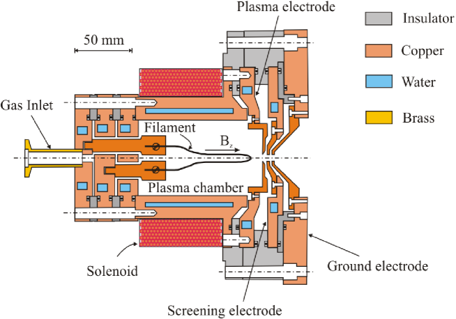
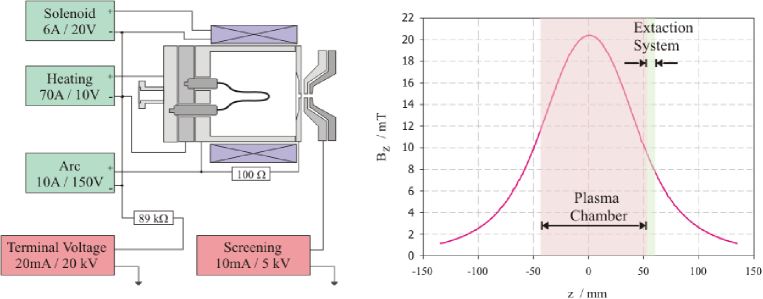
As shown in fig.1 the source consists of a plasma chamber with a hot tungsten filament and a triode extraction system. The cathode emits electrons which are accelerated to the cylindrical plasma chamber wall. Electrons are forced into cycloidal paths by an external solenoidal field, increasing their path lengths to the wall, and thereby, increasing the probability of an ionizing collision with neutrals. Fig.2 shows the block diagram of the source with power supplies and the on axis magnetic field produced by the solenoid. One can see, that almost a magnetic field level is present at the extraction system. Magnetic field levels at the plasma chamber centre up to were applied by coil currents up to . The heating filament as well produces a comparable magnetic field of around by heating current upto . This magnetic force does not have a significant effect on the ion beam, but does change the plasma properties significantly.
A triode extraction system was used. At normal settings the plasma electrode is held at positive potential, the screening electrode is held at a negative level of the plasma electrode potential. The space charge dominated beam current is given by the Child Langmuir Law,
| (1) |
is the current density, is the accelerating potential and is the acceleration gap length. In the source used was .
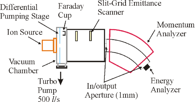
Fig.3 shows the experimental setup used for a characterization of the ion source. The source was mounted on a differential pumping chamber equipped with three turbo molecular pumps. A Faraday cup was installed in the same tank for beam current measurements. An emittance scanner of the grid slit type was mounted and a momentum analyzer was installed downstream.
3 beam
The helium beam consists of a single specie, singly charged ion beam for this source type, generated by the reaction
| (2) |
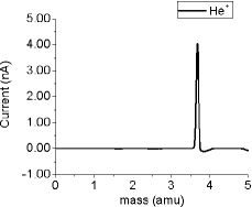
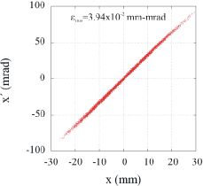
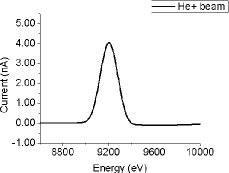
Fig.4 shows an example of a beam with current extracted at beam energy. A gas filling pressure of and arc potential were used as standard settings. The terminal can supply voltage levels up to . The current extracted was measured by a Faraday cup.
4 , , beams
The proton beam is extracted from a plasma fed by . The key reactions involved are,
| (3) |
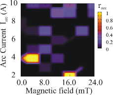
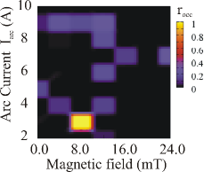
The last two processes are assumed to be important for an efficient production of protons in a small source[6][7][8]. It was figured out that the proton fraction depends upon plasma parameters. The whole parameter space of arc current and magnetic field was scanned at three different values of arc potential () and three different values of source filling pressure () to find the maximum fraction of individual species. To get a clear contrast in the plots for identifying the optimum settings for the production of the species of interest, for example for protons, the relative occurrence () was defined as
| (4) |
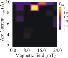
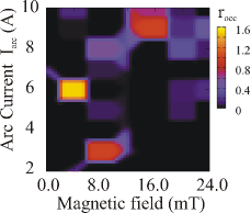
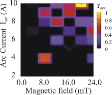
where is the relative percentage at that perticular set of parameters. In a similar way, the for and were defined. Fig.5 shows the relative occurrence of , and as function of arc current () and magnetic field at the gas filling pressure of and arc potential. At particular values of magnetic field and plasma density the relative occurrence of particular species is very high. Thus the graph shows an island kind structure.
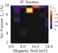
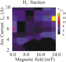
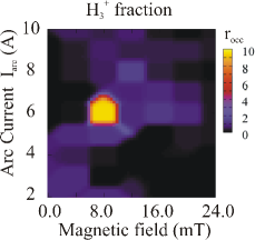
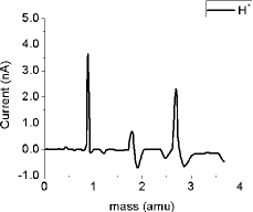
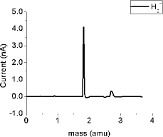
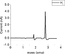
Fig.6 shows the mass spectra at the optimum values of relative occurrences. As optimum ratios at each of the separate island positions, about of proton corresponding to , about of corresponding to and about of corresponding to current were extracted at beam energy respectively.
When these graphs were plotted for different filling pressure or arc potential the island positions moved (see Fig.7 and 8) and the intensity decreased while retaining the island structure.

Typically, the used version of heating cathode should be changed after around of operation.
5 Conclusion
A proton beam containing of was extracted routinely for the beam transport experiments at Frankfurt University. Especially, this ion source provides and beams with individual ratios up to . The source can be tuned in a wide range of operating parameters to optimize the beam.
References
- [1] N. Joshi, et. al., Beam transport in toroidal magnetic field, EPAC’08, Genoa, June 2008, http://www.jacow.org , (to be published).
- [2] M. Droba, et. al., Design Studies on a Novel Stellarator type High Current Ion Storage Ring, EPAC’06, Edinburgh, June 2006,p.297-299, http://www.jacow.org.
- [3] R. Hollinger, P. Beller, K. Volk, M. Weber, H. Klein, The Frankfurt 200 mA proton source, Review of Scientific Instruments, Volume 71, Issue 2, pp. 836-838 (2000).
- [4] M. Maier, et. al., Status of the LINAC- Commissioning for the Heavy Ion Cancer Therapy Facility HIT, Proc. of the EPAC06 Conf., Edinburgh, p. 1571.
- [5] P. Garin, IFMIF: Status and Development, Proc. of the EPAC08 Conf., Genova, p. 974.
- [6] P. Groß, Untersuchungen zum Emittanzwachestum intensiver Ionenstrahlen bei teilweiser Kompensation der Raumladung, Ph. D. thesis, Johann Wolfgang Goethe Universität, 2000
- [7] R. Holinger, Ph. D. thesis, Johann Wolfgang Goethe Universität, 2000.
- [8] T. Morishita, et. al., High proton ratio plasma production in a small negative ion source, Review Scientific Instruments, vol 75, no.5, May 2004, p.1764-1766.