Wireless Information Surveillance via Proactive Eavesdropping with Spoofing Relay
Abstract
Wireless information surveillance, by which suspicious wireless communications are closely monitored by legitimate agencies, is an integral part of national security. To enhance the information surveillance capability, we propose in this paper a new proactive eavesdropping approach via a spoofing relay, where the legitimate monitor operates in a full-duplex manner with simultaneous eavesdropping and spoofing relaying to vary the source transmission rate in favor of the eavesdropping performance. To this end, a power splitting receiver is proposed, where the signal received at each antenna of the legitimate monitor is split into two parts for information eavesdropping and spoofing relaying, respectively. We formulate an optimization problem to maximize the achievable eavesdropping rate by jointly optimizing the power splitting ratios and relay beamforming matrix at the multi-antenna monitor. Depending on the suspicious and eavesdropping channel conditions, the optimal solution corresponds to three possible spoofing relay strategies, namely constructive relaying, jamming, and simultaneous jamming and destructive relaying. Numerical results show that the proposed technique significantly improves the eavesdropping rate of the legitimate monitor as compared to the existing passive eavesdropping and jamming-based eavesdropping schemes.
Index Terms:
Wireless information surveillance, proactive eavesdropping, spoofing relay, power splitting, beamforming, jamming.I Introduction
The great success of wireless communication technology has drastically improved our life during the past few decades. By providing high-speed wireless connectivity essentially anywhere, anytime, and between any pair of devices, contemporary wireless communication systems not only make our daily life increasingly more convenient, but also provide numerous new opportunities for applications and innovations in almost all fields, such as education, business, industry, etc. However, the ubiquitous accessibility of wireless communication systems also makes them more vulnerable to be misused by malicious users to commit crimes, jeopardize the public safety, and invade the privacy of others, etc. Therefore, it becomes increasingly important for the legitimate parties, such as the government agencies, to implement effective information surveillance measures to monitor any suspicious communication for various purposes such as intelligence gathering, terrorism/crime prevention and investigation, etc.
From an engineering design perspective, devising efficient schemes for wireless information surveillance calls for a paradigm shift from that for conventional wireless security [1],[2]. In wireless security, the eavesdroppers are treated as adversaries, whose eavesdropping potential should be minimized. Various wireless security mechanisms, both in physical layer [3] and across upper layers of communication system protocols design [4], have been proposed to prevent or minimize the information leakage to the unintended eavesdroppers. In particular, under the classic wiretap channel setup [5], significant efforts have been devoted to characterizing the secrecy capacity [6, 7, 8], defined as the maximum transmission rate at which the message can be reliably decoded at the legitimate receiver without leaking any useful information to eavesdropping receivers. For wireless surveillance, however, the monitor is regarded as a legitimate eavesdropper, whose eavesdropping rate over any suspicious channel should be maximized to effectively intercept the transmitted information over the air.
One straightforward approach for wireless information surveillance is passive eavesdropping, where the legitimate monitor only listens to the wireless channels of any suspicious users to decode their transmitted messages. However, this approach is effective only when the eavesdropping channel from the source to the legitimate monitor is better than the suspicious channel to the destination, so that the information sent by the suspicious source can be reliably decoded at the legitimate monitor. Yet this does not hold in practice if the legitimate monitor is located further away from the suspicious source compared to the suspicious destination. To overcome this limitation, a proactive eavesdropping scheme via cognitive jamming technique is proposed in [1], [2], where the legitimate monitor sends noise-like jamming signals to intentionally degrade the suspicious link, so as to induce the suspicious source to reduce transmission rate to be decodable at the legitimate monitor receiver. However, given the limited power budget for jamming, the eavesdropping performance cannot be improved if the suspicious channel capacity is higher than that of the eavesdropping channel even with the maximum-power jamming. Furthermore, there are also scenarios when it is desirable for the legitimate monitor to spoof the suspicious source to increase its transmission rate to achieve higher eavesdropping rate. In such cases, jamming is not effective and more intelligent strategies need to be devised for proactive eavesdropping.
To further enhance the information surveillance capability of legitimate monitors, we propose in this paper a new proactive eavesdropping approach via a so-called spoofing relay technique. Specifically, besides information eavesdropping, the legitimate monitor also acts concurrently as a relay to send spoofing signals to the suspicious destination and thereby induce the source to vary the transmission rate in favor of the eavesdropping performance. The underlying assumption is that adaptive rate transmission is adopted at the suspicious source based on the effective channel condition at the destination. Under this setup, if the eavesdropping link (from the source to the legitimate monitor) is stronger than the suspicious link (from the source to the destination), the legitimate monitor will enhance the effective channel of the suspicious link by forwarding a constructive source signal to the suspicious destination, which leads to higher transmission rate by the suspicious source, and thus higher eavesdropping rate. On the other hand, if the eavesdropping link is weaker than the suspicious link, the legitimate monitor will degrade the effective channel of the suspicious link via forwarding a destructive source signal and/or a noise-like jamming signal to the suspicious destination, so as to spoof the suspicious source to reduce its transmission rate to a level decodable by the eavesdropping monitor. Note that the proposed spoofing relay technique is quite general since it is applicable regardless of whether the eavesdropping link is stronger or weaker than the suspicious link. Furthermore, it includes the existing passive and jamming-based eavesdropping [1],[2] as special cases, and thus is expected to outperform these two benchmark schemes. Intuitively, the proposed spoofing relay scheme is strictly beneficial when either the eavesdropping link is stronger than the suspicious link (so that constructive relaying improves the eavesdropping rate), or when the eavesdropping link is too weak such that jamming alone is insufficient (so destructive relaying is needed), as will be verified later in this paper by numerical results. The main contributions of this paper are summarized as follows.
-
•
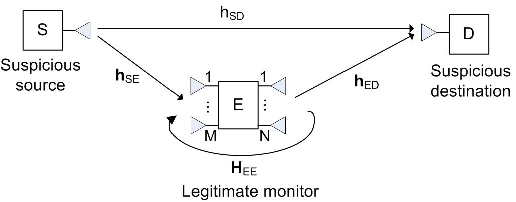
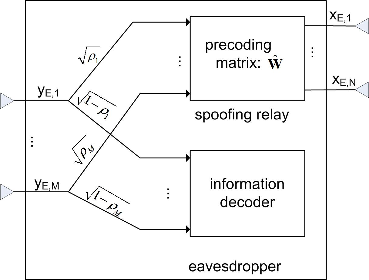
First, we model the system architecture for wireless information surveillance via a legitimate multi-antenna monitor, as shown in Fig. 1. A power splitting receiver111Notice that power splitting technique has also been used for separating the received signal for information decoding and energy harvesting in simultaneous wireless information and power transfer (SWIPT) systems [9],[10]. is proposed to split the received signal at each receiving antenna of the legitimate monitor into two parts, one for information eavesdropping and the other for spoofing relaying. An optimization problem is then formulated to maximize the eavesdropping rate by the legitimate monitor via jointly optimizing the power splitting ratios for all of its receiving antennas and the relay beamforming/precoding matrix for the transmitting antennas.
-
•
Next, we derive the optimal solution to the formulated problem by first solving two key sub-problems, which respectively find the maximum and minimum effective signal-to-noise ratio (SNR) at the suspicious link receiver by optimizing the relay precoding matrix at the legitimate monitor transmitter with fixed receiver power splitting ratios. Based on the obtained solutions, we further show that uniform power splitting, i.e., all receiving antennas at the legitimate monitor use the same power splitting ratio, is optimal for maximizing the eavesdropping rate with spoofing relaying, which thus leads to an efficient solution for the optimal power splitting ratios. Finally, the problem is solved with three possible relay strategies at the legitimate monitor, namely constructive relaying, jamming, and simultaneous jamming and destructive relaying, which are applied when the eavesdropping channel is better, weaker, and severely weaker than the suspicious channel, respectively.
- •
It is worth pointing out that under the classic physical-layer security framework, secure communication for wireless relay channels has been studied in various setups. Depending on the role of the relay node, such existing works can be loosely classified into three categories: (i) trusted relay that helps the source transmitter in improving the secrecy rate in the presence of the eavesdropper, via cooperative signal relaying to the destination or cooperative jamming to the eavesdropper [11, 12, 13]; (ii) untrusted relay from which the source transmitter wishes to keep the information confidential while engaging its help [14],[15]; and (iii) adversary relay that helps the eavesdropper, rather than the source transmitter, in decreasing the secrecy rate [16],[17]. On the other hand, proactive eavesdropping in different forms such as pilot contamination attack, false feedback, etc., has also been studied recently [18, 19, 20, 21, 22, 23, 24, 25, 26]. However, all the aforementioned works focus on the conventional wireless security design based on the information-theoretic secrecy capacity measure, which treats the eavesdroppers as adversaries and thus aims to minimize the information leakage to them. In contrast, for the proactive eavesdropping considered in this paper, the eavesdropper is employed by a legitimate monitor for the different purpose of information surveillance, and how to maximize its eavesdropping rate via optimally designing the spoofing relay strategy is a new problem that has not been studied in the literature.
The rest of this paper is organized as follows. Section II introduces the system model for proactive eavesdropping with a spoofing relay, and presents the problem formulation for eavesdropping rate maximization. Section III presents the optimal solution for the formulated problem, as well as a low-cost implementation that only requires one power splitter at the legitimate monitor receiver. In Section IV, numerical results are presented to compare the proposed proactive eavesdropping scheme with the two benchmark schemes. Finally, we conclude the paper in Section V.
Notations: In this paper, scalars are denoted by italic letters. Boldface lower- and upper-case letters denote vectors and matrices, respectively. denotes the space of complex-valued matrices. represents an identity matrix, and denote an all-zero and all-one matrix, respectively. For a matrix , its complex conjugate, transpose, Hermitian transpose, and Frobenius norm are respectively denoted as , , , and . For a vector , represents its Euclidean norm. denotes a diagonal matrix with the diagonal elements given in the vector . means that each element in is no greater than that in . For a complex number , represents its phase, and and denote its real and imaginary parts, respectively. The symbol represents the imaginary unit of complex numbers, i.e., .
II System Model and Problem Formulation
As shown in Fig. 1, we consider an information surveillance scenario, where the legitimate monitor E is intended to overhear a suspicious communication link from source S to destination D. We assume that both S and D have one single antenna each, whereas E is equipped with receiving and transmitting antennas. We consider that adaptive rate transmission is adopted at S based on the channel perceived at D. However, neither S nor D is aware of the presence of E, so that no dedicated coding as in conventional physical-layer security (see e.g., [3] and references therein) is applied to prevent the eavesdropping by E. On the other hand, the legitimate monitor E can conduct either passive or proactive eavesdropping, as discussed below.
II-A Passive Eavesdropping
With passive eavesdropping, E remains silent throughout the communication between S and D, but tries to decode the information from S. In this case, the channel capacity of the suspicious link from S to D, which is also assumed to be the transmission rate by S, is given by222The results in this paper can be readily extended to the practical scenario with non-Gaussian signaling [27], by e.g., inserting a gap in the capacity formula (1) as , where accounts for the capacity loss due to practical modulation and coding in use.
| (1) |
where is the complex-valued channel gain from S to D, is the transmit power by S, and is the power of the additive white Gaussian noise (AWGN) at D. On the other hand, the capacity of the single-input multiple-output (SIMO) eavesdropping channel from S to E is
| (2) |
where denotes the SIMO channel from S to the receiving antennas of E. If or equivalently , i.e., the legitimate monitor has a better channel than the suspicious destination, E can reliably decode the information sent by S with arbitrarily small error probability. As a result, the effective eavesdropping rate is given by . On the other hand, if , or the legitimate monitor has a weaker channel than the suspicious destination, then it is impossible for E to decode the information from S without any error. In this case, we define the effective eavesdropping rate as .333Note that in this case E may still extract useful information from its received signal. However, in this paper we consider a more stringent requirement that the message from S needs to be decoded at E with arbitrarily small error probability to achieve the wireless surveillance goal. Therefore, the effective eavesdropping rate can be expressed as
| (3) |
II-B Proactive Eavesdropping via Spoofing Relay
In this subsection, we propose a proactive scheme for the legitimate monitor via the spoofing relay technique to enhance the eavesdropping rate over passive eavesdropping. To enable continuous information surveillance with concurrent proactive spoofing relaying, we assume that E operates in a full-duplex mode with simultaneous information reception and spoofing signal transmission. As will become clear later, one key requirement for the spoofing relay technique is that the excessive time delay of the two effective signal paths (i.e., the direct link from the source to destination and that via the spoofing relay) is much smaller than the symbol duration to avoid causing inter-symbol interference (ISI). Therefore, we assume that the amplify-and-forward (AF) relaying strategy is adopted by E since it usually has smaller processing delay than other relay processing technique such as decode-and-forward (DF). Therefore, the received signal by the receiving antennas of E can be expressed as
| (4) |
where denotes the circularly-symmetric complex Gaussian (CSCG) distributed information-bearing symbol sent by S with transmit power , represents the loop channel from the transmitting antennas of E to its own receiving antennas, denotes the transmitted signal by E, and represents the antenna noise received by E. Note that the second term in the expression of in (4) is due to the full-duplex operation at E, which in general couples the input and output signals of E. To avoid circuit oscillations in practice as well as to suppress the self-interference from the loop channel, the input and output of E must be sufficiently isolated [28]. For ease of exposition, we assume that the ideal input-output isolation is achieved at E by designing that completely nulls the output of the loop-channel, i.e.,
| (5) |
Thus, the received signal by E in (4) reduces to . As shown in Fig. 2, to achieve simultaneous spoofing relaying and information eavesdropping at E under the AF operation, the received signal at each antenna of E is split into two parts, one for constructive/destructive information relaying aiming to enhance/degrade the effective channel of the suspicious link from S to D, and the other for information decoding so as to eavesdrop the message sent by S. Denote by the power splitting ratio of antenna , the signal vector split for information relaying can be expressed as
| (6) |
where represents the power splitting vector, and represents a vector obtained by taking element-wise square root. The transmitted signal by the transmitting antennas of E can then be expressed as
| (7) | ||||
| (8) |
where is the relay precoding matrix at E, and denotes the processing noise introduced during the relaying operation at E, which is assumed to dominate over the antenna noise ; thus, is ignored in (8). The transmit power by E is thus given by
| (9) |
By assuming that the processing delay due to the AF relaying at E is much smaller than the symbol duration, and hence is negligible, the signal received at D can be expressed as
| (10) | ||||
| (11) |
where denotes the multiple-input single-output (MISO) channel from the transmitting antennas of E to D, and is the AWGN at D. It is observed from (11) that by adjusting the power splitting ratio vector and the precoding matrix , the legitimate monitor E is able to alter the effective channel of the suspicious link from S to D. The capacity of the suspicious link is thus given by , where is the effective SNR at D, which can be obtained from (11) as a function of and as
| (12) |
where represents the transmit SNR by S. Note that the term in the denominator of (12) is due to the noise amplification by E.
On the other hand, at the information decoder of E, the split signal based on which the message from S is decoded can be expressed as
| (13) |
where denotes the AWGN at the information decoder of E. Thus, the information rate achievable by E with the optimal maximal ratio combining (MRC) over all the signal branches is , where is the SNR as a function of given by
| (14) |
To study the fundamental performance limit achievable by the legitimate monitor, we assume that perfect channel state information (CSI) of all links is available at E. Note that in practice, the loop channel can be estimated beforehand at the legitimate monitor. On the other hand, the channels and could be estimated at the legitimate monitor by overhearing the pilot signals sent by S and D, respectively. For the suspicious link channel , it could be obtained by overhearing the channel feedback sent from D to S.
II-C Problem Formulation
The objective of the legitimate monitor E is to jointly optimize the power splitting ratio vector and the relay precoding matrix so that the eavesdropping rate is maximized. Based on the definition in (3), the problem can be formulated as
| (15) |
where the zero-forcing (ZF) constraint follows from (5) and (7), and represents the maximum power available at E normalized by the noise power . (P1) is a non-convex optimization problem. However, by exploiting its structure, the optimal solution can be efficiently obtained, as shown next.
III Optimal Solution
To obtain the optimal solution to (P1), we first consider the ZF constraint . This implies that the precoding matrix must lie in the null space of . Let the (reduced) singular value decomposition (SVD) of be expressed as , where and contain the orthonormal left and right singular vectors of , respectively, with denoting the matrix rank of , and contains the positive singular values of . Further denote by with the orthogonal complement of , i.e., the concatenated matrix forms an orthonormal basis for the -dimensional space with . The precoding matrix satisfying the ZF constraint in (P1) can then be expressed as
| (16) |
where denotes the new matrix to be designed. It is not difficult to observe that in order for the ZF constraint to be feasible, we must have , or equivalently the rank of must satisfy . Since , one sufficient (but not necessary) condition is thus , i.e., more antennas at E should be allocated for transmission than that for reception.
By substituting (16) into (12), the effective SNR at D as a function of and can be expressed as
| (17) |
where denotes the projected channel of onto the null space of . Furthermore, since the link capacity and monotonically increase with the SNR and , respectively, (P1) thus reduces to
| (18) |
where the last constraint follows from the equality , , and due to the fact that . Note that (P2) is equivalent to (P1) in the sense that they have the same optimal value (except the logarithmic transformation between rate and SNR), and their optimal solutions are related by the simple linear transformation equation (16). (P2) is still a non-convex optimization problem, due to the non-concave objective function as well as the non-convexity of the first constraint. However, by exploiting the special structure of the SNR expressions for and , the optimal solution to (P2) can be efficiently obtained. Specifically, by firstly optimizing the precoding matrix with fixed power splitting vector , the maximum and minimum achievable SNRs (or equivalently the achievable SNR range) at D with fixed can be obtained. The problem (P2) then reduces to finding the optimal power splitting vector , as formulated in (P3) in Section III-C. The details are given next.
III-A Maximum Achievable SNR at D with Fixed
To obtain the optimal solution to (P2), it is noted that the SNR at E only depends on the power splitting ratio vector , rather than the precoding matrix . Thus, for any fixed , we first obtain the maximum achievable SNR at D, denoted as , by optimizing as
| (19) |
where we have defined .
Theorem 1.
The optimal solution to problem (19) is
| (20) |
where , , and . Furthermore, the corresponding optimal value is given by (21) shown at the top of the next page.
| (21) |
Proof:
Please refer to Appendix A. ∎
Theorem 1 shows that in order to maximize the SNR at D, the precoding matrix at E should be chosen such that the two signal paths from S to D, namely the direct link and that via the monitor relaying, add constructively, i.e., . We term such a strategy of the spoofing relay as constructive information forwarding, since it helps enhance the effective channel of the suspicious link from S to D. Furthermore, (20) shows that the optimal relay precoding matrix is given by a rank-1 matrix, with a simple MRC-based linear combining (by the term ) of the output of the power splitters cascaded by a maximal-ratio transmission (MRT) beamforming (by the term ) [27].
It is also noted from (21) that for any fixed power splitting ratios , the maximum achievable SNR at D depends on only via the term . In particular, if , i.e., no information forwarding is applied at E, we have , which corresponds to the special case of passive eavesdropping previously discussed in Section II-A. On the other hand, if and is sufficiently large, we have . This results in the maximum SNR achievable at D which is equivalent to that achieved by MRC-based signal detection jointly performed at E and D. However, in this case, there is no signal split for information decoding at the legitimate monitor and thus the effective eavesdropping rate will be zero.
III-B Minimum Achievable SNR at D with Fixed
Next, for fixed power splitting ratios , we study the minimum achievable SNR at D, denoted as , which can be obtained by solving the following optimization problem,
| (22) |
Theorem 2.
The optimal solution to problem (22) is
| (23) |
where is any unit-norm vector that is orthogonal to , i.e., , and and are the optimal solution to the following problem,
| (24) |
Proof:
Please refer to Appendix B. ∎
Theorem 2 shows that in order to minimize the SNR at D, the precoding matrix by E should be chosen such that the two effective signal paths from S to D add destructively, i.e., . Such a strategy at E is termed as destructive information forwarding, which degrades the effective channel of the suspicious link from S to D. Furthermore, similar to for maximizing SNR at D, in (23) for SNR minimization at D is also a rank-one matrix with a similar structure. However, although the MRT-based transmit beamforming still applies, the preceding combining vector for the power-splitting output is in general given by a linear combination of the MRC combining and its orthogonal vector . Note that although the power allocated along the direction does not forward any destructive source signal to D, it also contributes to the SNR degradation at D via jamming, i.e., amplifying the noise at E to D. Thus, the optimal relaying strategy by E for SNR minimization at D in general involves both destructive information forwarding and jamming.
Theorem 3.
The optimal solution and the corresponding optimal value of problem (24) are respectively given by (25) and (26) shown at the top of the next page,
| (25) |
| (26) |
where
| (27) | |||
| (28) |
Proof:
Please refer to Appendix C. ∎
The results in (25) and (26) show that if both and the split power for information relaying are sufficiently large (corresponding to the first case in (25) and (26)), the destructive relaying signal from E is able to completely cancel the signal of the direct path from S at D, and thus makes the SNR at D equal to zero. In this case, no dedicated jamming is needed () for SNR minimization at D. On the other hand, if destructive information relaying is unable to drive the SNR at D to zero with the given transmit power of E, both destructive relaying and jamming are in general needed for the SNR degradation at D. Furthermore, similar to that in (21), the minimum achievable SNR in (26) depends on only via the term . In particular, if , i.e., no information forwarding is applied at E, we have , which corresponds to jamming (merely noise amplification) with full power of E.
III-C Optimal Solution to (P2)
Now we obtain the optimal solution to problem (P2) based on the above results. Since given in (17) is a continuous function of , for any fixed power splitting ratio vector , the set of achievable SNRs at D is given by the interval , with and denoting the maximum and minimum achievable SNRs given in closed-forms by (21) and (26), respectively. As a result, (P2) reduces to finding the optimal power splitting ratios via solving the following optimization problem,
| (29) |
Theorem 4.
Without loss of optimality to (P3), the power splitting ratio vector can be expressed as for .
Proof:
Please refer to Appendix D. ∎
Theorem 4 shows that uniform power splitting (UPS), i.e., all the receiving antennas at E employ the same power splitting ratio, is optimal to . By substituting with and after some simple manipulations, in (II-B) and in (21) respectively reduce to the uni-variate functions
| (30) | |||
| (31) |
where . Furthermore, in (26) reduces to the uni-variate function (32) shown at the top of the next page,
| (32) |
where , and if , and otherwise, with .
As a result, reduces to finding the optimal single power splitting ratio via solving
| (33) |
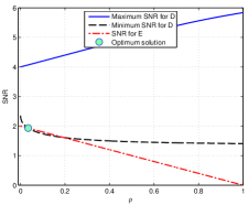
By noticing that in (30) is a linear decreasing function of , is essentially equivalent to finding the “best” intersection point between the line and the set
| (34) |
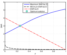
in the - plane, which can be optimally solved by separately considering the following three cases, as illustrated in Fig. 3.
Case 1: or as illustrated in Fig. 3(a). In this case, the legitimate monitor has a better channel than the suspicious receiver . Intuitively, should perform constructive information forwarding to enhance the effective channel of so as to increase the eavesdropping rate. It follows from Fig. 3(a) that the optimal solution to is given by the intersection point of the two curves and . As and are monotonically increasing and decreasing functions over , respectively, and , the equation has one unique solution , which can be efficiently obtained via bisection method.
Furthermore, if has sufficiently large power , can be obtained in closed-form, as given in the following lemma.
Lemma 1.
If and , the optimal solution to is , and the SNRs of both D and E are .
Proof:
Lemma 1 shows that by employing constructive relaying with the optimal power splitting ratio , E is able to increase the eavesdropping rate as compared to passive eavesdropping since . Furthermore, as increases, more power should be split at for constructive relaying to enhance the suspicious link SNR. In the extreme case when , i.e., the eavesdropper’s link is much stronger than the suspicious user’s link, half of the power of the received signal at should be split for information relaying, and the other half for information decoding (eavesdropping).
Case 2: or , as illustrated in Fig. 3(b). In this case, the eavesdropping link is worse than the suspicious link, but it becomes better if jamming with full power is applied at E to degrade the suspicious link. It follows from Fig. 3(b) that the optimal solution to is , i.e., no information forwarding and only jamming should be applied at E, where the normalized jamming power is given by so as to degrade the suspicious link SNR to the same level as that at . In this case, the SNR at both D and E is .
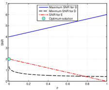
Case 3: or , as illustrated in Fig. 3(c). In this case, the legitimate monitor’s link is worse than the suspicious user’s link even after jamming with full power by E. Therefore, destructive information forwarding and jamming should be both applied at to further degrade the suspicious link SNR. It follows from Fig. 3(c) that the optimal solution to is obtained by solving in the interval , which can be reduced to a quartic equation and hence solved efficiently. Note that if more than one solutions exist, the one with the smallest magnitude is the optimal solution. On the other hand, if no solution exists, it implies that problem , and hence , is infeasible, i.e., the legitimate monitor is unable to degrade the suspicious user transmission rate to be decodable by E with its given transmit power.
III-D Low-Cost Implementation with One Single Power Splitter
The solution obtained in the preceding subsection in general leads to positive power splitting ratios at all receiving antennas of E (except for Case 2 where jamming only is optimal), i.e., , ; thus, in total power splitters need to be equipped at E, which could be costly in practice. In this subsection, we show that for practical implementation, one single power splitter is sufficient to achieve optimal eavesdropping, regardless of the number of receiving antennas .
Theorem 5.
There exists an optimal solution to such that the power splitting ratios are given by
| (35) |
Proof:
Please refer to Appendix E. ∎
Note that Appendix E gives a constructive proof of Theorem 5, where the optimal power splitting ratio vector satisfying (35) is obtained in closed-form (56) based on the optimal uniform power splitting vector to problem (P3). Therefore, in terms of computational complexity, the (semi-)binary power splitting solution in Theorem 5 is comparable to that of the uniform power splitting solution obtained in the preceding subsection, which are both quite efficient since they only require solving either a bisection search problem (for Case 1) or a quartic equation (for Case 3). However, in terms of practical implementation, the solution given in Theorem 5 is more cost-effective since it requires only one power splitter to be equipped at E, instead of as for the uniform power splitting scheme.
IV Numerical Results
In this section, numerical results are provided to evaluate the performance of the proposed proactive eavesdropping via spoofing relay technique. We assume that the suspicious source and the suspicious destination are separated by a fixed distance meters (m). The legitimate monitor is located on the same line connecting to , with the distance between and denoted as that varies between m and m for different eavesdropper locations. Such a setup could correspond to the macro-cell users (with typical cell radius on the order of km). Thus, the distance between and can be expressed as . We assume that uniform linear arrays with adjacent elements separated by half-wavelength are equipped at the transmitter and receiver of . Furthermore, we assume that all links are dominated by the line-of-sight (LoS) channels that follow the free-space path loss model. Unless otherwise specified, the number of transmitting and receiving antennas at are and , respectively. The operating frequency is assumed to be GHz. We define as the channel power ratio between the eavesdropping and the suspicious links, where all the channels including and are generated based on the eavesdropper’s location and the LoS path loss model. Furthermore, denote as the reference SNR received at with source transmission power and receiver noise power . We consider two benchmark schemes, namely passive eavesdropping as discussed in Section II-A, and proactive eavesdropping with jamming only [1], [2]. Note that with the definition given in (3), passive eavesdropping has positive eavesdropping rate only when has better channel than from the suspicious source , i.e., . On the other hand, jamming is helpful for enhancing the eavesdropping rate only when has weaker channel than , i.e., .
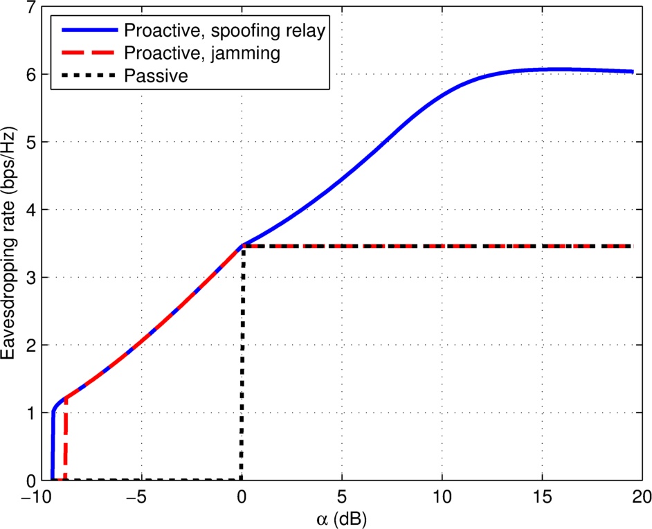
First, we study the effect of on the maximum eavesdropping rate achievable by the legitimate monitor with the three eavesdropping schemes. To this end, we assume that the legitimate monitor moves towards from the location with m to that with m. Correspondingly, the channel power ratio increases from around dB to dB. The transmission power by is fixed to a value such that the reference SNR dB, and the maximum transmission power at is set as . The eavesdropping rates versus with the three schemes are compared in Fig. 4. It is observed that when has a better channel than , i.e., (0 dB), both passive eavesdropping and jamming-based eavesdropping (with zero jamming power in this case) achieve a constant , which is equal to the channel capacity of the suspicious link from to . In contrast, the proposed proactive eavesdropping scheme with spoofing relaying achieves a significantly higher eavesdropping rate, since it is able to spoof the suspicious source to increase its transmission rate by constructively forwarding the source signal to , which is not possible in the two benchmark schemes. When has a worse channel than , i.e., (0 dB), the eavesdropping rate with the passive scheme drops to zero, since cannot reliably decode the information sent from . In contrast, as long as is not too small, the two proactive schemes can achieve strictly positive eavesdropping rate, since they both jam the suspicious link to spoof the source to decrease its transmission rate to be decodable at . Note that in this regime, the proposed spoofing relay technique degenerates to jamming (Case 2 as described in Section III-C), thus the two proactive schemes obtain identical rate performance. As further decreases, e.g., dB, is unable to decode the information sent by even with the two proactive schemes, and thus the eavesdropping rate drops to zero. However, it is worth noting that at around dB, the proposed spoofing relay technique still achieves strictly positive eavesdropping rate, whereas that with jamming only is zero. This corresponds to Case 3 as described in Section III-C, where both jamming and destructive information forwarding can be jointly applied to further degrade the suspicious link SNR for to decode the information sent by .
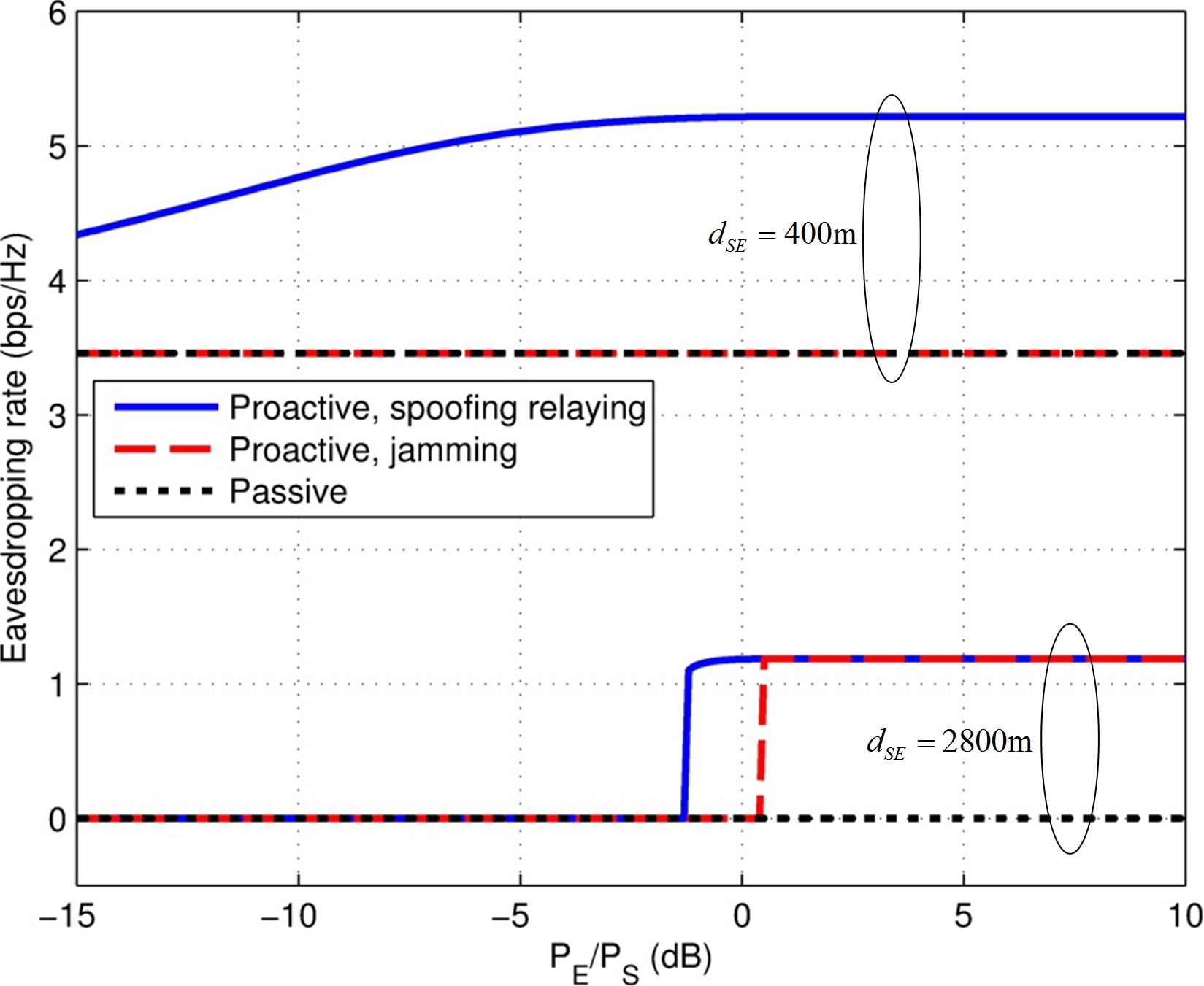
Next, we investigate the effect of the legitimate monitor’s power budget on the maximum achievable eavesdropping rate with the three considered schemes. We compare two setups with m and m, respectively. The transmission power by is fixed such that dB, whereas the power budget at the legitimate monitor varies such that the power ratio increases from dB to dB. Fig. 5 shows the maximum eavesdropping rate versus by the three eavesdropping schemes under the two setups. It is first observed that the eavesdropping rate by the passive scheme is independent of , since no transmission is performed at . Furthermore, for the case with m, the eavesdropping rate by the jamming scheme is also independent of , since no jamming is needed when the eavesdropping link is stronger than the suspicious link. In contrast, the eavesdropping rate with the proposed spoofing relay technique under m firstly increases with , and then approaches to a constant value as gets sufficiently large, which is in accordance with Lemma 1. For the case of m where has worse channel than , both the two proactive schemes have zero eavesdropping rate when is sufficiently small, whereas the rate increases to a positive value when exceeds certain thresholds. It is noted that if the eavesdropping link is stronger than the suspicious link (e.g., m), then the proposed scheme always outperforms the jamming-based scheme, regardless of the power budget at the relay. On the other hand, for m so that the eavesdropping link is weaker than the suspicious link, an excessive relay power about dB is required by jamming than the proposed scheme in order to achieve the same eavesdropping rate of around bps/Hz.
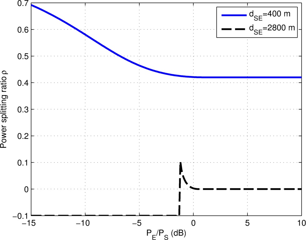
For the proposed spoofing relaying scheme, Fig. 6 plots the optimal power splitting ratio at versus . It is observed that for the case of m, firstly decreases with , since larger transmission power at requires less signal power to be split for information relaying, and hence more power can be split for eavesdropping. As gets sufficiently large, approaches to a constant value of , which is in accordance with that predicted by Lemma 1. On the other hand, for the case of m, problem (P1) is infeasible when is too small, which is indicated by the infeasible in Fig. 6. For between dB and dB, a small fraction of the signal power received at is split for destructive information forwarding. As increases to dB, becomes zero since jamming alone is optimal in this case, which is consistent with the results in Fig. 5.
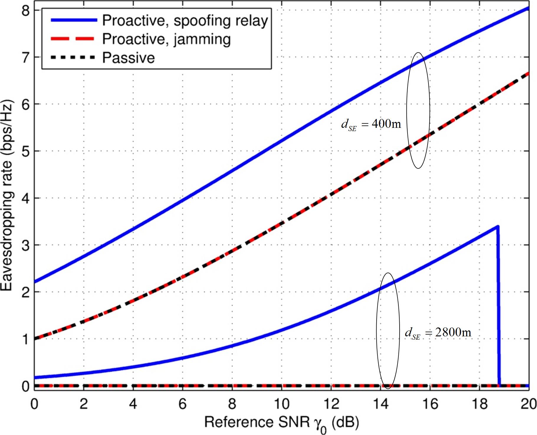
Next, we investigate the effect of source transmission power on the eavesdropping rate. Similar to that in Fig. 5 and Fig. 6, we consider two setups with m and m, respectively. The power budget at is fixed such that dB, whereas the transmission power by the suspicious source varies such that the reference SNR increases from dB to dB. Fig. 7 shows the maximum achievable eavesdropping rate by the three considered schemes versus under each of the two setups. It is first observed that for the case of m where has better channel than , the eavesdropping rate with all three considered schemes increases with . However, the proposed spoofing relaying scheme performs significantly better than the other two schemes, due to the constructive relaying performed at that enhances the effective channel capacity from to . For the case of m, the eavesdropping rate by both passive eavesdropping and jamming only is zero due to the poor channel between and . In contrast, the proposed spoofing relaying technique is able to achieve strictly positive eavesdropping rate for below a certain threshold, beyond which the eavesdropping rate drops to zero since the suspicious transmission rate cannot be degraded to a value decodable by with its given transmit power constraint .
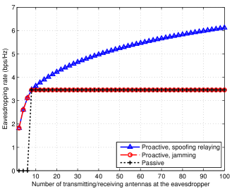
Lastly, by assuming equal number transmitting and receiving antennas at the eavesdropper, i.e., , Fig. 8 shows the eavesdropping rate versus for m, dB, and . Note that since the loop channel is of rank-1 under the LoS assumption, the ZF constraint (5) is feasible as long as . Fig. 8 shows that the performance of all the three eavesdropping schemes in general improves with the increasing of , which is expected due to the more powerful receiving/transmitting beamforming gains as more antennas are used. However, for the two benchmark schemes, no further improvement on the eavesdropping rate is possible for beyond , since the eavesdropping rate is fundamentally limited by the source transmission rate, which neither passive eavesdropping nor jamming is able to improve when the eavesdropping link becomes better than the suspicious link. In contrast, thanks to the constructive relaying, the proposed spoofing relaying technique is able to achieve continuous eavesdropping rate improvement as increases, though with a diminishing gain. This again shows the superior performance of the proposed eavesdropping strategy over the two benchmark schemes.
V Conclusions
This paper has studied the new wireless information surveillance problem in the general paradigm of wireless security. A novel proactive eavesdropping scheme with spoofing relaying technique has been proposed. With the proposed scheme, the legitimate monitor acts as a full-duplex relay for simultaneous eavesdropping and spoofing relaying to render the suspicious source to vary transmission rate in favor of the eavesdropping performance. The receive power splitting ratios and the transmit precoding matrix at the legitimate monitor are jointly optimized for eavesdropping rate maximization. Numerical results show that the proposed spoofing relay technique significantly enhances the information surveillance performance as compared to the two benchmark schemes with passive or jamming-based eavesdropping.
Appendix A Proof of Theorem 1
To show Theorem 1, we first apply the triangle inequality to (17), which yields
| (36) |
where equality holds if and only if is chosen such that the two effective signal paths from S to D add constructively, i.e., . Furthermore, since an arbitrary phase shifting of does not alter the feasibility of the power constraint in (19), problem (19) is thus equivalent to
| (37) |
Lemma 2.
The optimal solution to problem (37) is
| (38) |
where is the optimal solution to the following optimization problem
| (39) |
Proof:
We show Lemma 2 by construction. Suppose that an optimal solution to (37) is given by , with , and the resulting optimal value is . We then construct an alternative solution in the form of (38), i.e., , with
| (40) |
where the last inequality follows from the sub-multiplicativity property of the Frobenius norm, i.e., for any conformable matrices (vectors) and [29]. We aim to show that the newly constructed matrix is feasible to problem (37), and also returns an objective value no smaller than . To this end, we first show the following:
| (41) | ||||
| (42) | ||||
| (43) |
where (42) follows from and the Cauchy-Schwarz inequality , ; and (43) is true since must satisfy the power constraint of problem (37). The above result shows that the newly constructed matrix also satisfies the power constraint at E, and hence is feasible to problem (37). Furthermore, the following results can be obtained,
| (44) | ||||
| (45) |
Based on (44) and (45), it is not difficult to conclude that . In summary, for any optimal solution to problem (37), we can always construct a feasible solution in the form of (38) that achieves no smaller objective value; thus, must also be optimal. Furthermore, problem (39) is resulted by substituting (38) into (37). This completes the proof of Lemma 2. ∎
Appendix B Proof of Theorem 2
To show Theorem 2, we first apply the triangle inequality to (17), which yields
| (46) |
where equality holds if and only if is chosen such that the two effective signal paths from S to D add destructively, i.e., . Furthermore, since an arbitrary phase shifting of does not alter the feasibility of problem (22), the optimal solution to (22) can be obtained by solving
| (47) |
Next, we derive the optimal structure of the solution to (47). Recall that is a matrix of dimension . Define an -dimensional unitary matrix , where is the orthogonal complement of such that . Similarly, define an -dimensional unitary matrix , where . Then any matrix can be expressed as
| (48) |
where , , , and are the new optimization variables after unitary transformations by and . By substituting with (48), we have the following results:
| (49) | |||
| (50) | |||
| (51) | |||
| (52) |
It is observed from (49)-(52) that the objective value of problem (47) is independent of and . Besides, the left hand side (LHS) of the power constraint in problem (47) increases with and . Thus, without loss of optimality, we can set and . Furthermore, as both the objective value and the transmit power depend on via its norm only, we can assume without loss of optimality that for . Similarly, we may assume for without loss of optimality. Therefore, it follows from (48) that the optimal solution to (47) can be expressed as
| (53) |
By substituting (53) into problem (47), we obtain the optimization problem (24) for determining the optimal weighting coefficients and .
This completes the proof of Theorem 2.
Appendix C Proof of Theorem 3
Note that the objective value of problem (24) is always non-negative, and it equals to zero if . Thus, if is achievable, i.e., , the pair is obviously the optimal solution to (24). This corresponds to the first case of (25). For the remaining cases, it can be verified that at the optimal solution, the power constraint of (24) should be satisfied with equality, since otherwise, one can always increase to further minimize the objective value. Therefore, the variable can be eliminated by substituting with , and the problem reduces an uni-variate optimization problem, which can be solved by examining its first-order derivative. The details are omitted for brevity.
Appendix D Proof of Theorem 4
The key for proving Theorem 4 is to use the fact that all the three functions , , and depend on only via the term , where denotes the th element of . Assume that is an optimal solution to (P3), with the th element of given by , . We construct a new power splitting vector , with . It is obvious that , and thus the constraint is satisfied. Furthermore, we also have , and hence , , and . Therefore, the pair is also an optimal solution to (P3). This completes the proof of Theorem 4.
Appendix E Proof of Theorem 5
The proof of Theorem 5 is similar to that of Theorem 4, which exploits the fact that the power splitting vector affects the SNRs at both D and E only via the term . Let be the optimal UPS vector to problem (P3). If or , then Theorem 5 is already satisfied. Thus, we assume . In this case, it can be verified that there always exists an integer such that both the following inequalities hold,
| (54) | |||
| (55) |
where is the permutation operation such that . As a result, we define a new power splitting vector with binary power splitting (BPS) over receiving antennas such that
| (56) |
where
| (57) |
It can be verified that , and hence is satisfied. Furthermore, we have . Thus, must also be an optimal solution to problem . This completes the proof of Theorem 5.
References
- [1] J. Xu, L. Duan, and R. Zhang, “Proactive eavesdropping via jamming for rate maximization over Rayleigh fading channels,” IEEE Wireless Commun. Letters, vol. 5, no. 1, pp. 80–83, Feb. 2016.
- [2] J. Xu, L. Duan, and R. Zhang, “Proactive eavesdropping via cognitive jamming in fading channels,” submitted to IEEE Trans. Wireless Commun., [Online] Available: http://arxiv.org/abs/1512.02754.
- [3] Y. Liang, H. V. Poor, and S. Shamai, Information theoretic security, Foundations and Trends in Communications and Information Theory, 2009.
- [4] J. L. Massey, “An introduction to contemporary cryptology,” Proc. IEEE, vol. 76, no. 5, pp. 533–549, May 1988.
- [5] A. D. Wyner, “The wire-tap channel,” Bell Sys. Techn. Journ., vol. 54, no. 8, pp. 1355–1387, 1975.
- [6] A. Khisti and G. Wornell, “Secure transmission with multiple antennas –II: the MIMOME wiretap channel,” IEEE Trans. Inf. Theory, vol. 56, no. 11, pp. 5515–5532, Nov. 2010.
- [7] F. Oggier and B. Hassibi, “The secrecy capacity of the MIMO wiretap channel,” IEEE Trans. Inf. Theory, vol. 57, no. 8, pp. 4961–4972, Aug. 2011.
- [8] Y. W. P. Hong, P. C. Lan, and C. C. J. Kuo, “Enhancing physical-layer secrecy in multiantenna wireless systems: an overview of signal processing approaches,” IEEE Signal Process. Mag., vol. 30, no. 5, pp. 29–40, Aug. 2013.
- [9] R. Zhang and C. K. Ho, “MIMO broadcasting for simultaneous wireless information and power transfer,” IEEE Trans. Wireless Commun., vol. 12, no. 5, pp. 1989–2001, May 2013.
- [10] X. Zhou, R. Zhang, and C. K. Ho, “Wireless information and power transfer: architecture design and rate-energy tradeoff,” IEEE Trans. Commun., vol. 61, no. 11, pp. 4757–4767, Nov. 2013.
- [11] E. Tekin and A. Yener, “The general Gaussian multiple access and two-way wire-tap channels: Achievable rates and cooperative jamming,” IEEE Trans. Inf. Theory, vol. 54, no. 6, pp. 2735 2751, June 2008.
- [12] L. Lai and H. El Gamal, “The relay-eavesdropper channel: Cooperation for secrecy,” IEEE Trans. Inf. Theory, vol. 54, no. 9, pp. 4005–4019, Sept. 2008.
- [13] L. Dong, Z. Han, A. P. Petropulu, and H. V. Poor, “Improving wireless physical layer security via cooperating relays,” IEEE Trans. Signal Process., vol. 58, no. 3, pp. 1875–1888, Mar. 2010.
- [14] Y. Oohama, “Coding for relay channels with confidential messages,” in Proc. Inf. Theory Workshop, pp. 87–89, Sept. 2001.
- [15] X. He and A. Yener, “Cooperation with an untrusted relay: A secrecy perspective,” IEEE Trans. Inf. Theory, vol. 56, no. 8, pp. 3807–3827, Aug. 2010.
- [16] M. Yuksel and E. Erkip, “Secure communication with a relay helping the wiretapper,” in Proc. Inf. Theory Workshop, pp. 595–600, Sept. 2007.
- [17] M. Yuksel, X. Liu, and E. Erkip, “A secure communication game with a relay helping the eavesdropper,” IEEE Trans. Inf. Forensics Security, vol. 6, no. 3, pp. 818–830, Sept. 2011.
- [18] A. Chorti, S. M. Perlaza, Z. Han, and H. V. Poor, “On the resilience of wireless multiuser networks to passive and active eavesdroppers,” IEEE J. Sel. Areas Commun., vol. 31, no. 9, pp. 1850–1863, Sept. 2013.
- [19] X. Zhou, B. Maham, and A. Hjørungnes, “Pilot contamination for active eavesdropping,” IEEE Trans. Wireless Commun., vol. 11, no. 3, pp. 903–907, Mar. 2012.
- [20] A. Mukherjee and A. L. Swindlehurst, “A full-duplex active eavesdropper in MIMO wiretap channels: construction and countermeasures,” in Proc. IEEE Asilomar Conference on Signals, Systems and Computers, pp. 265–269, Nov. 2011.
- [21] D. Kapetanovic, G. Zheng, and F. Rusek, “Physical layer security for massive MIMO: an overview on passive eavesdropping and active attacks,” IEEE Commun. Mag., vol. 53, no. 6, pp. 21–27, June 2015.
- [22] D. Kapetanovic, G. Zheng, K.-K. Wong, and B. Ottersten, “Detection of pilot contamination attack using random training and massive MIMO,” in Proc. IEEE PIMRC, Sept. 2013, pp. 13–18.
- [23] A. A. Kapetanovic, D. Nahari, A. Stojanovic, and F. Rusek, “Detection of active eavesdroppers in massive MIMO,” in Proc. IEEE PIMRC, Sept. 2014, pp. 585–589.
- [24] Q. Xiong, Y.-C. Liang, K. H. Li, and Y. Gong, “An energy-ratio-based approach for detecting pilot spoofing attack in multiple-antenna systems,” IEEE Trans. Inf. Forensics Security, vol. 10, no. 5, pp. 932–940, May 2015.
- [25] J.-M. Kang, C. In, and H.-M. Kim, “Detection of pilot contamination attack for multi-antenna based secrecy systems,” in Proc. IEEE VTC Spring, May 2015, pp. 1–5.
- [26] J. K. Tugnait, “Self-contamination for detection of pilot contamination attack in multiple antenna systems,” IEEE Wireless Commun. Lett., vol. 4, no. 5, pp. 525–528, July 2015.
- [27] A. Goldsmith, Wireless Communications, Cambridge University Press, 2005.
- [28] A. Sabharwal, P. Schniter, D. Guo, D. W. Bliss, S. Rangarajan, and R. Wichman, “In-band full-duplex wireless: challenges and opportunities,” IEEE J. Sel. Areas Commun., vol. 32, no. 9, pp. 1637–1652, Sept. 2014.
- [29] R. A. Horn and C. R. Johnson, Matrix Analysis, New York: Cambridge Univ. Press, 2nd edition, 2013.