A Proposal for Semantic Map Representation and Evaluation
Abstract
Semantic mapping is the incremental process of “mapping” relevant information of the world (i.e., spatial information, temporal events, agents and actions) to a formal description supported by a reasoning engine. Current research focuses on learning the semantic of environments based on their spatial location, geometry and appearance. Many methods to tackle this problem have been proposed, but the lack of a uniform representation, as well as standard benchmarking suites, prevents their direct comparison. In this paper, we propose a standardization in the representation of semantic maps, by defining an easily extensible formalism to be used on top of metric maps of the environments. Based on this, we describe the procedure to build a dataset (based on real sensor data) for benchmarking semantic mapping techniques, also hypothesizing some possible evaluation metrics. Nevertheless, by providing a tool for the construction of a semantic map ground truth, we aim at the contribution of the scientific community in acquiring data for populating the dataset.
I Introduction
In the last years, semantic mapping has become a very active research area. Such increasing interest is motivated by the idea that if robots can understand the environment in which humans live, and the way they operate in it, they can also collaborate and act (i.e., have a more cognitive behavior). Nevertheless, the ability to communicate represents a strict requirement for collaboration among two or more agents. When dealing with humans, this can be naturally achieved by enabling robots to use spoken language, based on the learned semantic of the world. Associating symbols with numerical representations in fact is a key requirement for producing a robot that can use spoken language. Indeed, semantic mapping is the incremental process of mapping relevant information of the world (i.e., spatial information, temporal events, agents and actions) to a formal description supported by a reasoning engine, with the aim of learning to understand, collaborate and communicate.
Ongoing research mostly tries to address the problem by focusing on a subset of the information to be learned, and by considering an agent whose main abilities are navigation and object manipulation. In this way, strict requirements for communicative or collaborative behaviors are typically ignored. A relevant definition in this sense is given by Nüchter and Hertzberg [1], who describe a semantic map for a mobile robot as “a map that contains, in addition to spatial information about the environment, assignments of mapped features to entities of known classes. Further knowledge about these entities, independent of the map contents, is available for reasoning in some knowledge base with an associated reasoning engine”. Based on the same concept, several approaches have been proposed. These can be grouped in two main categories: fully automated methods for classification of locations and objects [2, 3, 4], and techniques, which exploit the support of the user in the knowledge acquisition and learning process [5, 6, 7]. While a comprehensive overview of the relevant work in this direction can be found in the survey by Kostavelis and Gasteratos [8], it is important to remark that even the simplest semantic map goes far beyond “simple” labeling of spatial features. In fact, even though they are built on top of sophisticate SLAM procedures, Computer Vision and Machine Learning algorithms, semantic maps must provide the possibility to reason over the acquired knowledge. Therefore they have to be formalized and represented in a proper way. Moreover, semantic mapping methods cannot be directly evaluated on the metrics and benchmarking datasets which are available for other algorithms, since they do not take into account any kind of reasoning. On the contrary, approaches proposed in literature (Section II) lack of any kind of standardization and typically underestimate these questions. In particular, two main issues emerge from the analysis of the state-of-the-art: 1) the absence of a common formalism for representing semantic maps and, consequently, 2) the lack of suitable validation and evaluation techniques. This puts a significant limitation on the research field, since it is difficult to understand the improvements over the state-of-the-art and to even compare available methods.
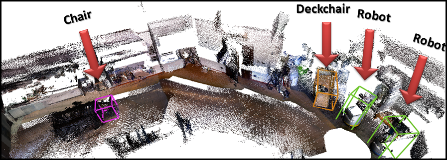
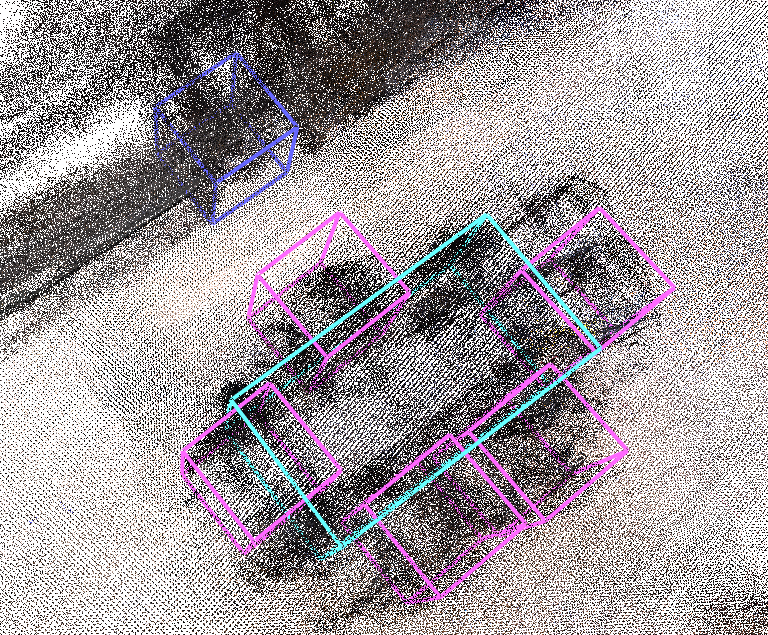
The aim of this paper is therefore twofold. First, we address the above highlighted issues, by proposing a formalization and a standardization in the representation of semantic maps (Section III). Second, we make a proposal for their evaluation, as well as for benchmarking semantic mapping methods, by means of a dataset based on real sensor data (Section IV). Moreover, by describing the procedure and providing usable software222The software is available at the following url: http://goo.gl/v7xSyl for building such a dataset (Section V), we invite the scientific community to contribute to its creation (see Fig. 1 for an example). Conclusions and open questions related to our proposal are finally reported in Section VI.
II Related Work
There exists a large literature on the problem of learning and representing the semantics of environments based on their spatial location, geometry and appearance [8]. This activity is usually referred to “semantic mapping”. Such a term, although originally describing a difficult process that deals with more heterogeneous information (i.e., not limited to spatial knowledge), has strong implications. Semantic maps should, in fact, not only assign a certain number of labels or properties to relevant features of the environment (like in [9, 3]), but also provide a representation of this knowledge in a form usable by the system.
As introduced in the previous section, one of the main issues of current research is the wide heterogeneity of the representations used for semantic maps. For example Galindo et al. [10] represent environmental knowledge by anchoring sensor data, that describe rooms or objects in a spatial hierarchy, to the corresponding symbol of a conceptual hierarchy. Such a conceptual hierarchy is based on a small ontology in description logic, which enables the robot to perform inference. The authors validate their approach by building their own domestic-like environment and testing the learned model by executing navigation commands. Pangercic et al. [11], instead, investigate the representation of “semantic object maps” by means of a symbolic knowledge base (in description logic) associated to Prolog predicates (for inference). Such a knowledge base contains classes and properties of objects, instances of semantic classes and spatial information. While profiling the time required by the semantic mapping process, the authors experiment their approach on a PR2 robot which has to open a cabinet and to detect handles based on an apriori given semantic map. Moreover, Bastianelli et al. [12] use a Prolog knowledge base containing both the specific knowledge of a certain environment and the general knowledge about a domain. The knowledge base is linked to the physical environment by means of a matrix like data structure generated on top of a metric map. Once again, the experimental validation is based on qualitative evaluations of the robot behavior, given a certain command and the learned semantic map. Riazuelo et al. [13] instead describe the RoboEarth cloud semantic mapping system, which is composed of an ontology, for coding concepts and relations, and a SLAM map for representing the scene geometry and object locations. In particular, a recognition module identifies objects based on a local database of CAD models, while the whole system is integrated with an OWL ontology.
The other problem, which emerges as a consequence of the variety of representations, is the absence of a standard suitable validation and evaluation procedure. In addition to previous examples, Zender et al. [5] generate a representation ranging from sensor-based maps to a conceptual abstraction, encoded in an OWL-DL ontology of an indoor office environment. However, except for individual modules, their experimental evaluation is mainly qualitative. Pronobis and Jensfelt [7], instead, represent a conceptual map as a probabilistic chain graph model and evaluate their method by comparing the robot belief to be in a certain location against the ground truth. Gunther et al. [4] perform a sort of semantic aided object classification based on an OWL-DL knowledge base. The evaluation is based on the rate of correctly classified objects. Finally, Handa et al. [14] propose a synthetic dataset, which could be eventually extended with semantic knowledge and used as a ground truth for comparing semantic mapping methods. However, even when noise is introduced, fictitious data never reflect a real world acquisition.
Note that none of the cited works can compare the performance of their semantic mapping method against those of other similar systems. Starting from these considerations we propose a standard methodology for representing and evaluating semantic maps. In particular, we describe a formalization which includes a reference frame, spatial information and a set of logic predicates. Such a formalization is thought to be used as a general structure of the representation that all the semantic maps have to include and can extend. Moreover, in addition to proposing an evaluation metric, we suggest the procedure for the creation of a semantic mapping dataset. In particular, such a dataset is based on real sensor data enriched with semantic information.
III Semantic Map Representation
As previously stated, in order to define a map to be “semantic”, we require that knowledge is represented in a suitable manner. In fact, this enables additional information to be inferred from the map, whenever a reasoning engine is associated to it. For this reason, in this section, we propose a formalization of a minimal general structure of the representation that should be implemented in a semantic map. This representation has to play the role of common interface among all the semantic maps, and can be easily extended or specialized as needed.

In the general formalization that we are describing, such a representation is defined as a triple
| (1) |
where:
-
•
is the global reference system in which all the elements of the semantic map are expressed;
-
•
is a set of geometrical elements obtained as raw sensor data. They are expressed in the reference frame and describe spatial information in a mathematical form. is the subset of semantically relevant elements;
-
•
is a set of predicates, among which is-a(X, Y) and instance-of(X, Y) are mandatory. has to be compliant with the concept hierarchy shown in Fig. 2. , with , contains the predicates that provide an abstraction of the elements in .
Note that the definition of a unique reference frame allows to associate the elements of the subset with those of . Moreover, the requirement that is composed of geometrical elements obtained as raw sensor data, gives the opportunity to define an additional functionality on top of our representation. Indeed, as we will explain in Section IV, we are interested in the possibility to get the actual sensor data, given a specific pose in the map expressed according to . For what concerns , instead, the predicates is-a and instance-of represent respectively: the subclass relation, meaning that if is-a(B, A) holds, the class B is a subclass of the class A and every instance of B is also an instance of A; the membership relation, meaning that if instance-of(a, A) holds, the individual a belongs to the class A. Additionally, some predicates can have a function-like behavior, meaning that they can occur only once for each individual. For example, if dealing with the classes Person and IDNumber, the predicate hasId(X, Y) occurs only once for each instance of Person and IDNumber.
To give a general idea, let us suppose we are building a semantic map for a robot operating and interacting with people in a mall. In this case, we can use our representation and choose to be a set of points, like a unique point cloud modeling the 3D map of the environment. For what concerns , we can extend the concept hierarchy of Fig. 2 as follows:
-
•
being a person an element of interest, we can define a class Person and add the predicate is-a(Person, Physical_Thing);
-
•
a specialization of the class Location can be introduced for the shops and corridors, by defining the classes Shop, Corridor and adding the predicates is-a(Shop, Location), is-a(Corridor, Location);
-
•
a Connecting_Architecture can be specified in such a way that it always connects an element of the class Shop and one of the class Corridor;
-
•
since a shop could use advertisements for promoting itself, we can define a class Advertisement, add the predicate is-a(Advertisement, Abstract_Thing) and define a new predicate hasAdvertisement(X, Y), where X could be an instance of Shop and Y an instance of Advertisement.
Finally, we can select as reference frame the global frame of a 3D map.
IV Semantic Map Evaluation
Once we are given the representation schema presented in Section III, a metric and one shared environment, then it is possible to perform a comparison between two different methods on the basis of the semantic maps they generate. For this reason, we have to define one or more metrics that allow for a quantitative evaluation of each method. Then, we have to find an environment in which to perform this kind of experiments. While some Robotics Innovation Facilities exist333http://www.echord.eu/facilities-rifs/ to this purpose, it is still not easy to retrieve common locations and environments, mainly due to logistic, physical and economic constraints. For these reasons, while hypothesizing some metric in Section IV-A, we suggest the construction of a dataset of semantic maps according to the proposed representation schema. In particular, the set of geometrical elements should be built with real sensor data. In this way, it is possible to simulate the robot navigation, as well as its sensor acquisition. This can be done by defining a projection function that transforms the elements of into the associated sensor domain. For example, in the case of a RGB-D camera the geometrical elements are projected in a depth and RGB image, while in the case of a laser they are projected into a vector of range values.
Such a dataset is a ground truth of each environment and therefore it can be used to make comparisons based on specific metrics. Of course, the set cannot be fully satisfactory, since it is not feasible to take into account all the possible semantic knowledge. For this reason, it is likely that a user might need to extend it. In this case, it is important to update the original ground truth so that it becomes more and more complete and that everyone can test their system on the same dataset.
IV-A Evaluation Metric Hypotheses
In this section, we hypothesize some possible evaluation metrics to be used for comparison between two semantic maps which are compliant with our previous proposal. Given a representation and the ground truth , an evaluation metric can be defined as
| (2) |
Note that the reference frame of and coincide: this is easily achievable by applying the transformation offset between the original frame of and of . The definition of the operators and determines the metric itself. For example, can be a distance between geometrical elements, according to Table I, while the operator could return two sets of predicates and such that:
| (3) |
| Points | Lines | Planes | ||
| Points | ||||
| Lines | ||||
| Planes | ||||
The lower the cardinality of and , the better is the semantic representation. However, this does not consider the fact that the subset contains some reference to spatial information (which could be measured again by metric criteria). A solution to this problem could be the redefinition of as an operator which returns two sets of predicates and , and a distance such that:
| (4) |
For example, suppose that the ground truth contains a table and a chair correctly positioned. If the table is missing in the set of the robot semantic map , from our metric in Eq. 3 we obtain that has cardinality . Indeed, in this case the robot would not be able to execute the command “go to the table”. Conversely, if the table belongs to , the cardinality is and the robot is able to execute the command. Similarly, if the object is not well positioned in any distance from Table I would be much bigger than zero, and the robot would execute the command by reaching a wrong location. Additional metrics could be defined on different criteria like the processing time, the distance traveled by the robot, the number of sensor readings processed, etc.
V Dataset Construction
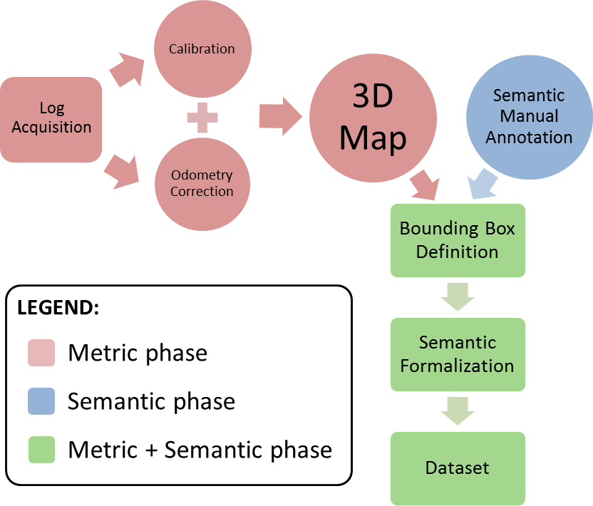
Since the construction of the dataset is based on the representation proposed in Section III, and it consists of the combination of spatial and semantic information, any approach compliant with that could be applied. In this section we describe our method for the generation of a ground truth, in which the set consists of a 3D point cloud, implements the proposed concept hierarchy and contains abstractions of bounding boxes. In particular, in order to collaborate with a larger community of researchers, we consider low cost sensors (i.e., RGB-D cameras like Microsoft Kinect and Asus Xtion) which can be easily found on any robot. Note that building a 3D map with this kind of sensors, leads to multiple open issues. Still, even if with an additional manual refinement, our software allows to build such maps. As shown in Fig. 3, this process is composed of several steps, which can be divided into metric and semantic phases. First, we acquire data in order to generate a 3D map and we perform a preliminary manual annotation of the objects inside the environment. Then, by associating semantic information and volumes in the 3D map, in the form of bounding boxes, we obtain the desired semantic map. Of course, sensor calibration prior to data acquisition is highly recommended (see Section V-B for more details).
V-A Data Acquisition
The data acquisition step can be divided in two different parts, one related to the 3D map, the other to the semantic annotations for elements of interest inside the environment. While manually collecting semantic annotations is relatively easy, although tedious, 3D data acquisition results to be more challenging due to the limitations of low cost sensors.
The generation of a 3D map requires the acquisition of a log capturing the income of the robot sensors while moving around the environment. In particular, this should contain the robot odometry (or laser data) and the camera stream (both for depth and RGB). While taking the log, one should pay attention to steer the robot so that at least one camera does not see only a flat surface. Indeed, structures like a floor, a wall or two parallel planes do not help the mapping system, due to their poor geometrical information.
V-B Sensor Calibration
The calibration of a sensor is the process of correctly computing its internal parameters, as well as its pose with respect to the robot reference frame. Extracting the right internal parameters improves the data generated by the sensor reducing its intrinsic error. For example, in the case of a depth camera, this corresponds to determine its camera matrix and distortion parameters. Computing the correct pose of a sensor, instead, allows to accurately express data measurements with respect to a different reference frame.
In order to perform sensor calibration and supposing to use RGB-D cameras on the robot, logs111A log is obtained by acquiring and recording the required sensor data. are required. In particular, choosing one of the cameras as a reference, we have:
-
1.
intrinsic calibration logs, containing the stream of the -th RGB-D sensor, for the calibration of the internal parameters of its depth camera (refer to [15] for more details on how to acquire data);
-
2.
sensor-base calibration log, containing the robot odometry (or laser data) and the camera stream, for calculating the pose between the robot and reference RGB-D sensor (the robot should slowly translate and rotate while the reference sensor sees at least 3 planes, each of them being non parallel with all the others);
-
3.
sensor-sensor calibration log (at least), containing the stream of the cameras, for computing the pose of RGB-D sensors with respect to the reference one (all the cameras should see, at least once, the same part of the environment while always respecting the condition of the previous point);
Common RGB-D cameras are affected by a substantial distortion in the depth channel. Not considering this distortion leads to systematic drifts in the estimate of the robot pose while mapping. This calibration is performed by following the procedure explained by Di Cicco et al. [15] on the intrinsic calibration logs. At the end of this procedure, it is possible to reduce the intrinsic error which normally affects the sensors data (i.e., walls that should be flat, look curved on the edges).
Another goal of the calibration procedure is to find the pose of one of the cameras (reference) with respect to the robot frame, and the relative offsets (translation and rotation) between all the other cameras and the reference. The software we developed provides two different tools to compute these offsets. The first one performs the computation of the transform between the robot frame and the reference depth camera. By using the sensor-base calibration log we estimate the motion of the camera in a small region. Taking as reference the odometry of the robot, this tool casts a least square problem that minimizes a cost function which depends on the sensor transform and returns . The second tool, instead, allows the computation of the offset between pairs of depth cameras. The main idea is to use the sensor-sensor calibration log to generate, for each camera, an independent point cloud. In this way, each sensor produces a cloud starting from its own reference frame. Once this is done, our registration algorithm can be run between pairs of point clouds. The output of the alignment determines the relative translation and rotation between the origins of the point clouds and thus between the sensors.
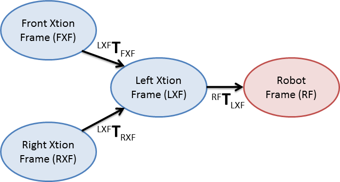
At the end of the calibration we are able to construct a tree of sensor pose transformations (see Fig. 4). From this tree, it is possible to compute the transformation between any two nodes, by a simple offset concatenation.
V-C Data Processing
Once all the data is acquired, the 3D map can be built. To this end, the point clouds recorded in the log are aligned generating a set of local maps. A local map is a point cloud constructed by aligning and integrating a sequence of depth sensor data while the robot moves in the environment. This is obtained through the use of a point cloud registration algorithm based on the work by Serafin et al. [16]. A new local map is started whenever one of the two following statements holds:
-
•
the estimate of the robot (or equivalently the camera) movement is greater than a certain amount. This allows to limit the growth of the local map in terms of dimension;
-
•
the point cloud registration algorithm detects that the last alignment is not good (with possibility of inconsistency). This is necessary in order to avoid to introduce errors inside the local map.
The local map generator uses the robot odometry as initial guess for the point cloud alignment. However, a good odometry estimation is not always available. In this case (but this is useful in general), if the robot comes with a 2D laser, it is possible to use as initial guess the transformation provided by the scan matcher developed as part of our software. The 3D map is represented as a pose graph [17], where each local map is connected to the previous and following one by means of a transformation. More in detail, nodes of the pose graph represent local maps, with their position and orientation in a global frame. Edges, instead, are relative transforms between local maps. The benefits of this metric representation are that it allows to add/remove anytime information and update an existing map. Indeed, by using a tool provided in our software, inconsistencies in the map can be manually fixed. More specifically, the user can select and align two nodes of the graph at time and add a new edge between them. This, together with the optimization of the pose graph [18], leads to the elimination of inconsistencies and thus, to a refined map.
V-D Combining 3D Map and Semantic Data
Once both the 3D map and the semantic annotations are available it is possible to combine them by means of a geometric abstraction like a volume in the map. In our case, we define such a volume to be a bounding box (i.e., a parallelepiped) containing all the geometric elements to which we want to attach the same semantic information.
After all the bounding boxes are assigned, we formalize the predicates (compliant with the conceptual hierarchy) in OWL-DL, by using Protégé 444http://protege.stanford.edu/. Bounding boxes, in particular, belong to the subset and they are formalized by means of classes like Size, Position and Shape.
V-E Dataset Example
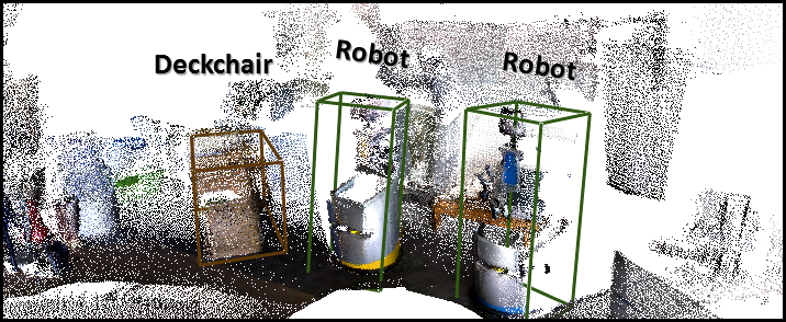
We performed the procedure described so far on a set of data specifically acquired during the RoCKIn Camp555http://rockinrobotchallenge.eu/ held in the ECHORD++ Robotic Innovation Facility of Peccioli666http://www.echord.eu/facilities-rifs/the-peccioli-rif/, in Italy. In particular, this is a domestic environment with several rooms and everyday objects built to foster benchmarking of robotic applications, to test their robustness, and to support standardization efforts. While a detail of the 3D map of the environment is shown in Fig. 5, the whole dataset is hosted online (http://goo.gl/v7xSyl) and contains a ground truth representation which is compliant with the requirements stated in Section III. Namely, a 3D point cloud with an associated reference frame and the corresponding OWL-DL ontology compose the first example of a dataset for semantic maps.
VI Discussion
In this paper we defined a methodology for representing semantic maps. In particular, we designed a formalization of their representation which includes both spatial and semantic knowledge. On top of this, we made some hypotheses for metrics and evaluation criteria, based on the idea that a ground truth for semantic maps exists. Note that the procedure we proposed for building a dataset is based on real sensor data. This allows to simulate robot navigation inside the environment, breaking down logistic, physical and economic barriers for a fair comparison between different semantic mapping methods. Finally, we provided useful documented open-source software for building such a dataset (http://goo.gl/v7xSyl). We invite, in this way, the scientific community to contribute in populating the dataset with more and more annotations and environments. In addition to all of this, we have also shown a first real example of ground truth for a semantic map. Open challenges, however, still remains. Future work, for example, should be oriented to the definition of a standard metric of evaluation.
References
- [1] A. Nüchter and J. Hertzberg, “Towards semantic maps for mobile robots,” Robotics and Autonomous Systems, vol. 56, no. 11, pp. 915–926, 2008.
- [2] N. Blodow, L. C. Goron, Z.-C. Marton, D. Pangercic, T. Ruhr, M. Tenorth, and M. Beetz, “Autonomous semantic mapping for robots performing everyday manipulation tasks in kitchen environments,” in Intelligent Robots and Systems (IROS), 2011 IEEE/RSJ International Conference on. IEEE, 2011, pp. 4263–4270.
- [3] O. M. Mozos, H. Mizutani, R. Kurazume, and T. Hasegawa, “Categorization of indoor places using the kinect sensor,” Sensors, vol. 12, no. 5, pp. 6695–6711, 2012.
- [4] M. Gunther, T. Wiemann, S. Albrecht, and J. Hertzberg, “Building semantic object maps from sparse and noisy 3d data,” in Intelligent Robots and Systems (IROS), 2013 IEEE/RSJ International Conference on. IEEE, 2013, pp. 2228–2233.
- [5] H. Zender, O. M. Mozos, P. Jensfelt, G.-J. Kruijff, and W. Burgard, “Conceptual spatial representations for indoor mobile robots,” Robotics and Autonomous Systems, vol. 56, no. 6, pp. 493–502, 2008.
- [6] C. Nieto-Granda, J. G. Rogers, A. J. Trevor, and H. I. Christensen, “Semantic map partitioning in indoor environments using regional analysis,” in Intelligent Robots and Systems (IROS), 2010 IEEE/RSJ International Conference on. IEEE, 2010, pp. 1451–1456.
- [7] A. Pronobis and P. Jensfelt, “Large-scale semantic mapping and reasoning with heterogeneous modalities,” in Robotics and Automation (ICRA), 2012 IEEE International Conference on. IEEE, 2012, pp. 3515–3522.
- [8] I. Kostavelis and A. Gasteratos, “Semantic mapping for mobile robotics tasks: A survey,” Robotics and Autonomous Systems, 2014.
- [9] N. Goerke and S. Braun, “Building semantic annotated maps by mobile robots,” in Proceedings of the Conference Towards Autonomous Robotic Systems, Londonderry, UK, 2009.
- [10] C. Galindo, A. Saffiotti, S. Coradeschi, P. Buschka, J.-A. Fernandez-Madrigal, and J. Gonzalez, “Multi-hierarchical semantic maps for mobile robotics,” in Intelligent Robots and Systems, 2005.(IROS 2005). 2005 IEEE/RSJ International Conference on. IEEE, 2005, pp. 2278–2283.
- [11] D. Pangercic, B. Pitzer, M. Tenorth, and M. Beetz, “Semantic object maps for robotic housework-representation, acquisition and use,” in Intelligent Robots and Systems (IROS), 2012 IEEE/RSJ International Conference on. IEEE, 2012, pp. 4644–4651.
- [12] E. Bastianelli, D. Bloisi, R. Capobianco, F. Cossu, G. Gemignani, L. Iocchi, and D. Nardi, “On-line semantic mapping,” in Advanced Robotics (ICAR), 2013 16th International Conference on. IEEE, 2013, pp. 1–6.
- [13] L. Riazuelo, M. Tenorth, D. Marco, M. Salas, D. Gálvez-López, L. Mosenlechner, L. Kunze, M. Beetz, J. Tardos, L. Montano et al., “Roboearth semantic mapping: A cloud enabled knowledge-based approach,” IEEE Transactions on Automation Science and Engineering (T-ASE): Special Issue on Cloud Robotics and Automation, vol. 12, no. 2, 2015.
- [14] A. Handa, T. Whelan, J. McDonald, and A. Davison, “A benchmark for RGB-D visual odometry, 3D reconstruction and SLAM,” in IEEE Intl. Conf. on Robotics and Automation, ICRA, Hong Kong, China, May 2014.
- [15] M. Di Cicco, L. Iocchi, and G. Grisetti, “Non-parametric calibration for depth sensors,” in Proc. of the 13th International Conference on Intelligent Autonomous Systems. (IAS 13), 2014.
- [16] J. Serafin and G. Grisetti, “Using augmented measurements to improve the convergence of icp,” in 4th International Conference on Simulation, Modeling, and Programming for Autonomous Robots (SIMPAR), ser. LNCS 8810. Springer, 2014, pp. 566–577.
- [17] G. Grisetti, R. Kummerle, C. Stachniss, and W. Burgard, “A tutorial on graph-based slam,” Intelligent Transportation Systems Magazine, IEEE, vol. 2, no. 4, pp. 31–43, 2010.
- [18] R. Kummerle, G. Grisetti, H. Strasdat, K. Konolige, and W. Burgard, “g 2 o: A general framework for graph optimization,” in Robotics and Automation (ICRA), 2011 IEEE International Conference on. IEEE, 2011, pp. 3607–3613.