Beam Charge Measurement for the g2p/GEp experiments
Abstract
The g2p/GEp experiments used a solid polarized target, where the polarization of the target is sensitive to temperature and radiation. The beam current was limited to 5-100 nA during the experiment to avoid too much depolarization of target (The typical Hall A running condition for beam current is 1 to 100 ). The measured charge was further used to get the accurate physics cross sections. New BCM (Beam Current Monitor) receivers and a DAQ system were used to measure the beam current at such a low current range. A tungsten calorimeter was used to calibrate the BCMs. This technical note summarizes the calibration procedure and the performance of the BCMs.
University of Science and Technology of China
1 Setup
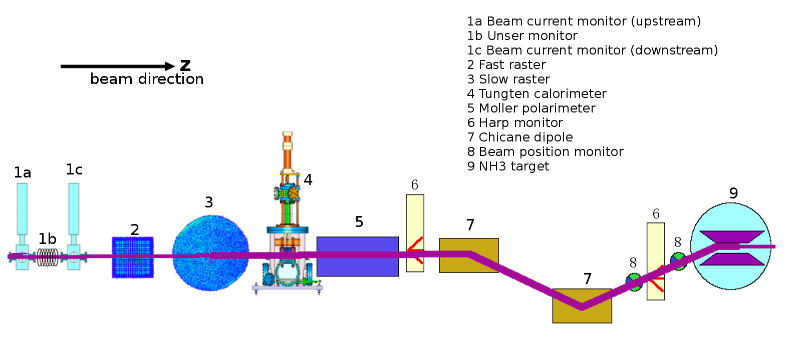
The BCM system used for the g2p [1] and GEp [2] experiments contains two RF cavities (1a and 1c in Fig. 1), BCM receivers with associated data-acquisition (DAQ) system, and a tungsten calorimeter for calibration. The traditional calibration method using an Unser monitor [3] (1b in Fig. 1) would not work at low current because it has an accuracy of 0.3 . Using a Farady cup [4] in the injector region to calibrate BCMs there and then using the calibrated BCMs in the injector region to cross-calibrate the BCMs in Hall A has about the same accuracy due to the beam loss in the machine. The setup is shown in Fig. 1.
1.1 BCM receiver
Since the original RMS-to-DC converter [5] did not work at low current, new BCM receivers were designed by John Musson and his colleagues from the JLab instrumentation group for the purpose of achieving a reasonable signal/noise (S/N) ratio in the beam current range of several nanoampere to several micro-ampere [6]. The design diagram is shown in Fig. 2.
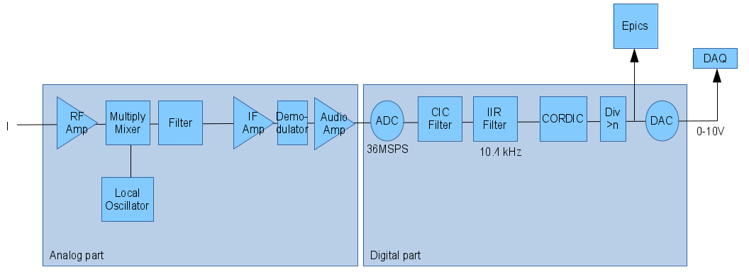
The receiver consists of an analog part and a digital part. The analog part includes the amplifier and the mixer. The multiply mixer converts the ratio frequency (RF) signal to the intermediate frequency (IF) signal. The signal is digitized by a 36 MSPS ADC, and applied by a cascaded-integrator–comb (CIC) filter and an infinite-inpulse-response (IIR) filter (10.4 kHz). The CORDIC system is used to get the amplitude and phase of the digital signal [6]. The 20-bit digital signal is converted back to 0-10V analog signal to match the existing Hall A DAQ system using a 18-bit DAC. A DIV unit is used to intercept the signal from 20-bit to 18-bit by applying an adjustable bit shift. More details can be found in [6].
1.2 Data acquisition system
The BCM data from the receivers were passed on the DAQ system as shown in Fig. 3.
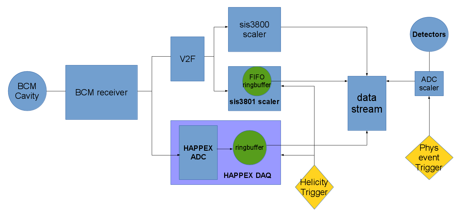
The voltage signal from receiver was split and sent to the Voltage to Frequency (V2F) module and the HAPPEX ADC.
1.2.1 Helicity
The beam is polarized in injector before going to the CEBAF accelerator. The polarization is controlled by a helicity control board (VME) [7]. The helicity control board generates several signals which relative to each other. It controls the high voltage supply to change the orientation of the polarization of laser, which is used to generate the polarized electron beam with GaAs photogun by using the method of optical pumping. Meanwhile the helicity control board sends signals to the DAQ system in the hall in order to get the helicity based information. During the experiment the helicity setting was the same as the QWEAK experiment in Hall C, as shown in table 1.
| Mode | Free clock |
|---|---|
| T-Settle | 70 |
| T-Stable | 971.65 |
| Helicity Pattern | or |
| Reporting delay | 8 window |
| Helicity board frequency | 960.015 Hz |
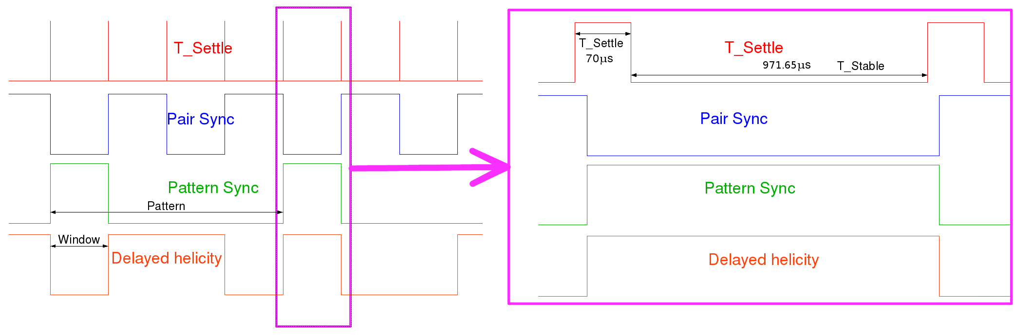
Four helicity signals were sent to hall during the experiment via optical fibers, which named T-Settle (or MPS), pattern_sync (or QRT), pair_sync, and delayed helicity (Fig. 4). The quartet helicity pattern is used for the experiment to minimize the system error, which is “” or “”, one pattern is composed with four helicity windows. The pattern_sync indicates the first window of one pattern. The T-Settle signal is used to indicate if the helicity is valid. The high-level T-Settle (70 ) indicates the helicity flips, or has unsure helicity states, while the low-level T-Stable (971.65 ) indicates the reliable helicity states. The pair sync signal flips in each helicity window, which is used as the redundancy information. The helicity flip signals sent to the halls are 8 windows delayed with respect to the actual helicity flip signals, and need to be taken care of in decoding. More details about the helicity decoder can be found in [8].
1.2.2 Scaler
The V2F converts the DC voltage signal from the BCM receiver to a frequency signal in order to readout the scalers for counting. The SIS380x scaler has two modes selected by a jumper on the board: SIS3800 and SIS3801.
SIS3800 scaler
The SIS3800 scaler counts the charge, clock and trigger signals for each event, and delivers them to the data stream when the event trigger is accepted. The counter data for the SIS3800 is only cleared at the beginning of the run, thus the SIS3800 is used to get the counts for the whole run.
SIS3801 scaler
The SIS3801 is used to get the helicity gated information. Fig. 5 shows the workflow of the SIS3801 scaler
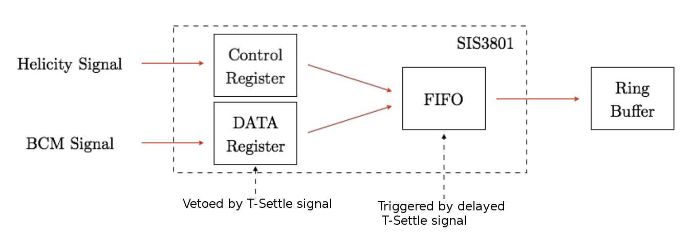
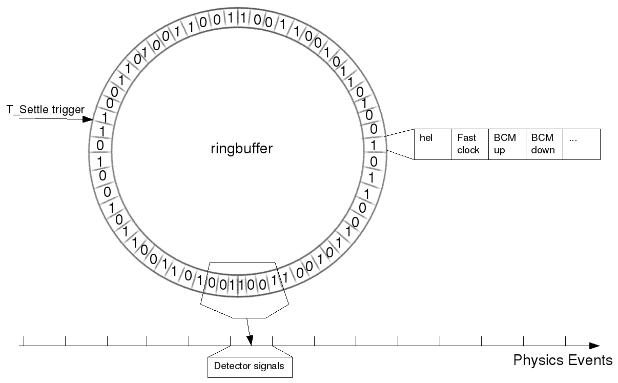
. The scaler is controlled by the T-Settle signal. The data registers count the charge, clock and trigger signals only in the T-Stable part of the helicity window. The counts are reset by the high-level T-Settle. A delayed T-Settle, the Pattern Sync, and the delayed helicity are also sent to the control register. Those information are saved in the FIFO (First-In-First-Out) register triggered by the delayed T-Settle signal. The FIFO is used as a ringbuffer (Fig. 6) before merging to the standard DAQ system.
1.2.3 HAPPEX DAQ
The HAPPEX DAQ were designed for the parity violation experiments. This DAQ was reprogrammed and reassembled for the g2p/GEp experiments.
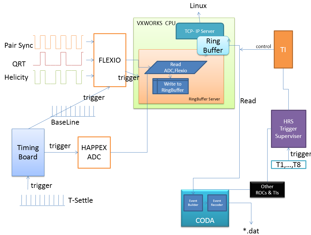
The HAPPEX DAQ contains a timing board (VME) [9], several 18-bit ADCs [10], a flexible IO (FLEXIO, VME) [11], a trigger interface module (TI), and a VxWorks CPU. The diagram of HAPPEX DAQ is shown in Fig. 7.
Timing board
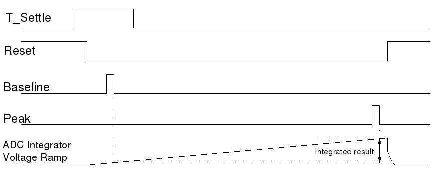
The timing board generates several time signals to control the start and stop integration time of the ADCs. The T-Settle signal is used as the trigger source for the timing board. Based on the trigger signal, the timing board generates a set of signals (Fig. 8). The reset signal controls the ADC integration. The delay time between the baseline signal and the peak signal is used as the integration time, and the digital value difference between them is used as integrated result. The DAC module in the timing board was used as a debugging source during the experiment.
HAPPEX ADC
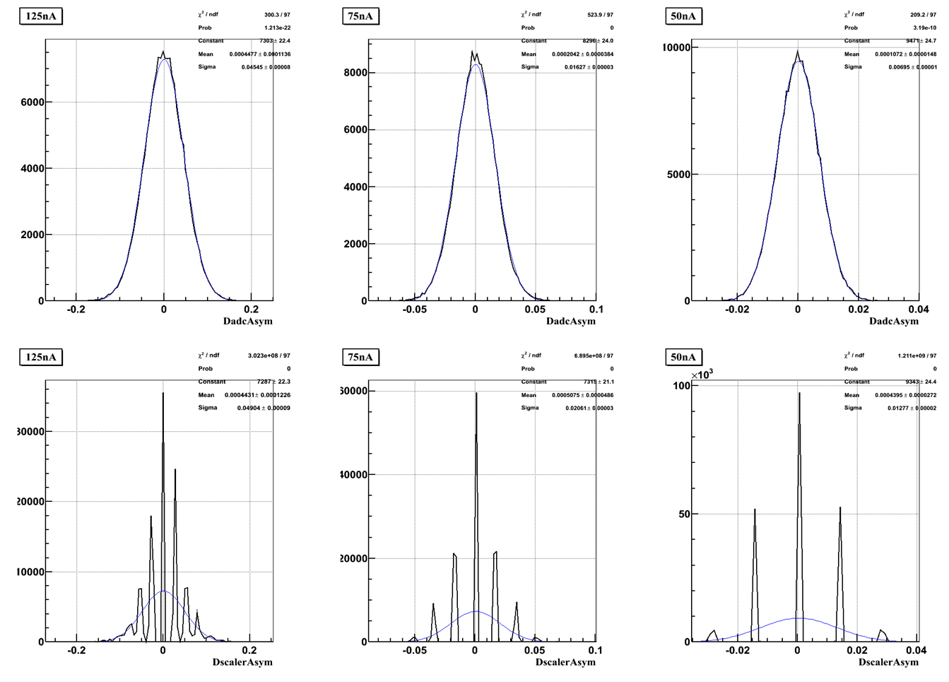
The HAPPEX ADC is designed for high bit resolution (18-bit) and a small non-linearity () for measuring small parity violating asymmetries to high precision. From the asymmetry measurement test (Fig. 9), the bit resolution for the HAPPEX ADCs were much better than the one for the scalers. The integration time of the HAPPEX ADCs controlled by the timing board is 875 , a little bit smaller than the helicity period (1041.65 ). The HAPPEX ADCs record more precise position and current information than the FASTBUS 1881 ADCs (with an integration time less than 50 during the experiment).
Flexible IO
The flexible IO is used to record the digital information. The baseline signal peak from the timing board triggers the flexible IO to record the helicity signals. It also provides a trigger signal for the ringbuffer.
Ring Buffer
A VxWorks CPU controls the data reading from the HAPPEX ADCs and the flexible IO to the ringbuffer server in the CPU. The ringbuffer is an array saved in the register of the CPU. Each element in array includes the information of helicity, charge, clock signals for this helicity states (Fig. 6). For more reliable performance and less CPU occupation, a trigger is used instead of checking the pair sync polarity all of the time. The trigger from the flexible IO has the same period as the T-Settle. Each trigger causes the CPU to read out the data from the flexible IO and the ADCs once. A trigger interface controlled by the HRS trigger supervisor reads the data from the ringbuffer server to the data-stream. For the online debugging, a TCP-IP server was running on the CPU to readout the data from the ringbuffer from any Linux computer at any time.
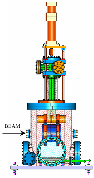
1.3 Tungsten Calorimeter
A tungsten calorimeter [12] is located downstream of the BCMs and the two rasters [13] for calibrating the BCMs by measuring the beam induced temperature rise, as shown in Fig. 10.
The chamber that holds the tungsten is pumped down to vacuum to minimize heat loss. The tungsten is in three positions for the different purpose:
-
1.
Beam charging, the tungsten is in beam position. All of the incoming beam electrons hit the tungsten. The temperature is increasing during this period.
-
2.
Equilibrating, the tungsten moves out of the beam pipe but doesn’t touch the cooling plate. The beam turns off. The temperature stabilizes. The measurement of the temperature occurs in this period.
-
3.
Cooling, the tungsten moves to the cooling plate to cool down the tungsten.
For the temperature measurement, six resistance temperature detectors (RTDs) are mounted on the outer surface at each end of the tungsten slug.
2 Calibration of the BCMs
Calibration data were taken several times during the experiment. In order to achieve the uniform heat load from the beam over the tungsten surface, the rasters were turned on during the BCM calibration. The limited size of the ringbuffer caused potential loss of data when the read-out speed was lower than the read-in speed. For the deadtime consideration, the DAQ system only read out no more than 50 sets data from the ringbuffer. An additional clock trigger with a frequency larger than 20 Hz ( 960 (helicity frequency) / 50) was added to avoid data loss in the ringbuffer recorded in the data-stream. The clock signal was needed for calculating the pedestal slope of the scaler and the ADC. For the HAPPEX ADC, the helicity entries were used as the clock.
The pedestal slope is defined as the accumulated counts or ADC values per unit time when there is no beam. The value of it depends on the frequency of the clock source. It needs to be removed for extracting the real accumulated counts caused by beam. There are two types of clock: fast clock and slow clock. The frequency of the fast clock was 103.7 KHz, while the frequency of the slow clock was 1 KHz. The calibration was taken for each of them.
A complete calibration period is shown in Fig. 11.
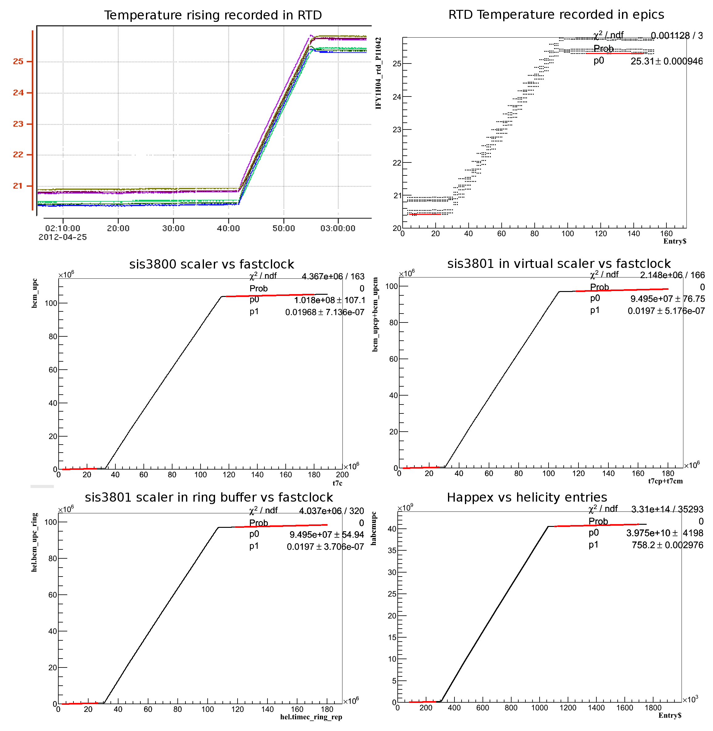
The total temperature rise is used to calculate the total charge. When the beam just off, the temperature readouts keep fluctuating until the heat is uniform in the tungsten. The zero-order polynomial fits are taken before the beam charging and after the temperature become stable when the tungsten is in the equilibrating position. The relationship between the total charge and the temperature rise is:
| (1) |
where is the heat capacity of tungsten. It was measured by Ahamad Mahmoud before the experiment [14]. The result is shown in Fig. 12

, with the value of . is the average temperature from the 6 RTDs.
There are several devices needed to be calibrated, and each one has its own special condition. The detail calibration procedures for each device are as follows.
2.1 Calibration for SIS3800 scaler
A reset signal was sent to the SIS3800 scaler at the beginning of the run to clear the counts. Since the scaler was found to cause high deadtime, only clock signals were sampled for each event, while other signals were sampled for each 1000 events. Also the DAQ read the scaler once at the end of the run.
The middle left picture in Fig. 11 is for the SIS3800 calibration. The rise in the graph is the period when the beam hits the tungsten, corresponding to the rise in the top left. The relation of the total charge and the counts is defined as:
| (2) |
where is the total BCM counts accumulated in the scaler, is the total clock counts accumulated in the scaler. The is the value of the pedestal slope, which is calculated from the first-order polynomial fits before and after the beam. To get the value, two time points are chosen before and after the beam heats the tungsten. Using the and the between these two time points and combining with the charge calculated from the temperature, the value is then determined.
The beam current is calculated from the calibration constants as:
| (3) |
where and are defined as the BCM counts per second and clock counts per second.
2.2 Calibration for SIS3801 scaler
To calibrate the SIS3801 scaler it is necessary to accumulate all of the counts for each helicity window without any loss of data. There are two methods to get the total counts. One is using the sum counts from two virtual scalers. The offline analyzer [15] automatically accumulates the total counts for positive helicity states and negative helicity states, which present two independent variables (positive and negative virtual scaler) in the raw data. Another is accumulating all of the counts from the ringbuffer. The helicity decoder was used to check if data were lost. The calculated calibration constants are the same from the two methods. The procedures are similar to the SIS3800. The relation of the total charge and the counts is defined as:
| (4) |
where the and are counted from the SIS3801 scaler. The value of uses the same value from tungsten as in section 2.1, thus it is considered as the whole charge in the whole helicity window. Since the SIS3801 does not count for 70 for each 1041.65 , the slopes calculated for the SIS3801 are larger than the slope for the SIS3800. If we denote as the readout from SIS3801 in each helicity entry, the recorded in the SIS3801 for one helicity window is equal to , where is the frequency of the fast clock, and is the duration of T-Stable. The beam current is then calculated as the charge divide the duration of the whole helicity window :
| (5) |
Note the constants in equation (4) are used to calculate the charge in the whole helicity window. If one need to know the absolute charge in T-Stable, an additional factor of is needed to be applied.
2.3 Calibration for HAPPEX ADC
To calibrate the HAPPEX ADC, the are accumulated for all of the events between two time periods as the total counts. The entries in the HAPPEX DAQ are used as the time stamp. The relation of the total charge and the counts is defined as:
| (6) |
Similar as the SIS3801 scaler, the ADC only accumulate during the integration time. The beam current is calculated as:
| (7) |
Where is the readout ADC value. Note the charge calculated using equation (6) is the charge in the whole helicity window.
2.4 Uncertainty
The uncertainty of the calculated charge from the tungsten calorimeter comes from the beam energy, RTD, measured tungsten heat capacity, and the heat loss. The ARC measurement has a relative uncertainty of [16], which contributes to the uncertainty of calculated charge of 2 per 1 K temperature rise (for 2.2 GeV beam energy), which is negligible compared to the total charge received in tungsten calorimeter of 30 during the calibration. The uncertainties of the RTDs are 12.5 mK [17], which contributes an uncertainty of . The uncertainty of heat capacity contributes per 1 K temperature rise. The Hall A calorimeter thermal and mechanical design limits heat losses to 0.2 % level if the measurement is within 20 min [12], which causes the uncertainty of calculated charge additional 0.2 %. The total uncertainty is 0.68 % for the calculated charge from the tungsten calorimeter.
By comparing the difference between the upstream and downstream BCMs, the fluctuations between the two are below for 90 % of the runs. The relative differences between them for 90 % of the runs are below 0.7 %, as shown in Fig. 13
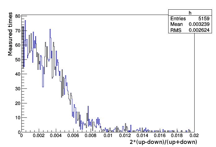
. The differences indicate the uncertainty due to the stability of the BCMs is 0.7 %. Combined with the calibration uncertainty of the tungsten calorimeter, the total uncertainty of BCMs is 1 %.
Fig. 14 shows the stability of the calibration with time during 3/13/2012 - 5/18/2012.
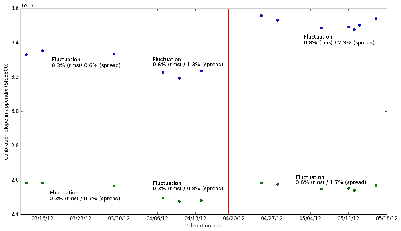
The calibration constants were stable at the level of 1 % for most of the time with following exceptions when there were condition changes:
-
•
Begin - Mar.17, third arm downstream scaler abnormal
-
•
Mar.18 - Apr.2, left arm upstream scaler noisy
-
•
Apr. 2, calibration constants changed 34% for both BCMs
-
•
Apr.2 - Apr.9, right arm SIS3801 not working
-
•
Apr.9, changed right arm scaler channel for BCM
-
•
Apr. 19, calibration constants changed 9% for the upstream BCM and 4% for the downstream
-
•
Near May.12, third arm SIS3801 not working
-
•
May.13 - May.14, downstream BCM broken
3 Calibration constants
The calibration constants are shown in the Appendix Tables 1-9. The gain settings of the bcm receivers for each periods are list below, the values after the date are:
A_Pre_Gain_1/A_Pre_Gain_2/A_Mag_Div
B_Pre_Gain_1/B_Pre_Gain_2/B_Mag_Div
IQ_Filter_K
Mag_Filter_K
-
•
Begin - Mar.2 18:39:42 Gain changing
-
•
Mar.2 18:39:43 - Mar.5 10:00:12 10/10/1 9/9/1 3 4
-
•
Mar.5 10:00:13 - Mar.5 10:27:40 Gain changing
-
•
Mar.5 10:27:41 - Mar.6 8:51:39 10/10/1 9/9/1 1 4
-
•
Mar.6 8:51:40 - Mar.6 13:45:43 10/13/1 9/9/1 1 4
-
•
Mar.6 13:45:44 - Mar.6 13:49:05 Gain changing
-
•
Mar.6 13:49:06 - Mar.7 17:20:10 29/30/4 27/27/4 1 4
-
•
Mar.7 17:20:11 - Mar.7 17:23:25 Gain changing
-
•
Mar.7 17:23:25 - Mar.10 13:12:53 29/30/4 27/27/4 1 4
-
•
Mar.10 13:12:54 - Mar.10 13:33:15 Gain changing
-
•
Mar.10 13:33:16 - end 40/41/4 40/43/4 1 4
References
- [1] A. Camsonne, J. P. Chen, D. Crabb and K. Slifer, spokesperson, JLab E08-027 (g2p) experiment.
- [2] J. Arrington, D. Day, R. Gilman, D. Higinbotham, G. Ron and A. Sarty, spokesperson, JLab E08-007 (GEp) experiment.
- [3] K. Unser, IEEE Transactions on Nuclear Science 28 (1981) 2344.
- [4] R. Kazimi, et al., Proc. of Particle Accelerator Conference IEEE 0-7803-3503 (1996) 2610.
- [5] J.-C. Denard, High Accuracy Beam Current Monitor System for CEBAF’s Experimental Hall A, 2001 Particle Accelerator Conference, Chicago (2001) 2326 – 2328.
- [6] J. Musson, Functional Description of Algorithms Used in Digital Receivers, JLab Technical Report No. JLAB-TN-14-028.
-
[7]
S. H. Roger Flood, R. Suleiman,
Helicity
Control Board User’s Guide, JLab Internal Manual (unpublished).
URL http://hallaweb.jlab.org/equipment/daq/HelicityUsersGuideFeb4.pdf -
[8]
C. Gu,
Helicity
Decoder for E08-027, JLab Technical Report, E08-027 Collaboration
(unpublished).
URL http://hallaweb.jlab.org/experiment/g2p/collaborators/chao/technotes/Chao_TechNote_HelicityDecoder.pdf -
[9]
Specification
of HAPPEX II ADC Timing Board, Revision 1, JLab Technical Report
(unpublished).
URL http://hallaweb.jlab.org/experiment/g2p/technotes/others/TimingBoard.pdf -
[10]
R. Michaels,
Precision
Integrating HAPPEX ADC, JLab Technical Report (unpublished).
URL http://hallaweb.jlab.org/parity/prex/adc18/prex\_adc18\_spec.ps -
[11]
E. Jastrzembski,
A
Flexible Vme Input/Output Module, JLab Technical Report (unpublished).
URL https://coda.jlab.org/drupal/system/files/pdfs/HardwareManual/misc/FLEXIO.pdf - [12] M. Bevins, A. Day, et al., Mechanical and Thermal Design of the CEBAF Hall A Beam Calorimeter, in: Proceedings of 2005 Particle Accelerator Conference, 2005, pp. 3819–3821. doi:10.1109/PAC.2005.1591634.
-
[13]
Pengjia Zhu, et al,
Beam
Position Reconstruction for the g2p Experiment in Hall A at Jefferson Lab,
Nuclear Instruments and Methods in Physics Research Section A: Accelerators,
Spectrometers, Detectors and Associated Equipment 808 (2016) 1 – 10.
doi:http://dx.doi.org/10.1016/j.nima.2015.10.086.
URL http://www.sciencedirect.com/science/article/pii/S0168900215013200 - [14] G2P Internal Elog, https://hallaweb.jlab.org/dvcslog/g2p/173.
-
[15]
O. Hansen, ROOT/C++ Analyzer
for Hall A.
URL http://hallaweb.jlab.org/podd/index.html -
[16]
J. Alcorn, et al.,
Basic
instrumentation for Hall A at Jefferson Lab, Nuclear Instruments and
Methods in Physics Research Section A: Accelerators, Spectrometers, Detectors
and Associated Equipment 522 (3) (2004) 294 – 346.
doi:http://dx.doi.org/10.1016/j.nima.2003.11.415.
URL http://www.sciencedirect.com/science/article/pii/S0168900203033977 -
[17]
Y. Rousseau,
Calibration
of the Calorimeter, JLab Technical Report (unpublished).
URL http://hallaweb.jlab.org/experiment/g2p/technotes/others/calorimeter\%20RTD.pdf
Appendix
| current(nA) | 280 | 25 | 50 | 75 | 100 |
| energy(MeV) | 2253.13 | 2252.94 | 2252.94 | 2252.94 | 2252.94 |
| time | 03/03/12 09:30 PM | 03/13/12 04:00 PM | 03/16/12 10:15 PM | 03/29/12 12:21 AM | 04/07/12 03:00 PM |
| Avail period | Start 3.10 13:25 | 3.10 13:33 3.17 10:00 | 3.10 13:33 3.17 10:00 | 3.27 21:00 4.2 14:00 | 4.2 18:00 4.9 9:00 |
| run avail(left SIS3800 up) | Start 3051 | 3052 3295 | 3052 3295 | broken | 3660 4695 |
| run avail(left SIS3800 down) | Start 3051 | 3052 3634 | 3052 3634 | 3052 3634 | 3636 4695 |
| run avail(left SIS3801 up) | Start 3051 | 3052 3295 | 3052 3295 | broken | 3660 4695 |
| run avail(left SIS3801 down) | Start 3051 | 3052 3634 | 3052 3634 | 3052 3634 | 3636 4695 |
| run avail(left HAPPEX up) | Start 3051 | 3073 3634 | 3636 4695 | ||
| run avail(left HAPPEX down) | Start 3051 | 3073 3634 | 3636 4695 | ||
| runnumber | 2665 | 3149 | 3254 | 3437 | 3856 |
| SIS3800 upslope(slowclk) | 1.37309e-06 | 3.32775e-07 | 3.34603E-07 | 2.30692e-07 | 3.22991E-07 |
| SIS3800 uppedslope(slowclk) | 5.24344E+00 | 2.04717E+00 | 2.01363E+00 | 2.40785E+00 | 2.01757E+00 |
| SIS3800 downslope(slowclk) | 1.30711e-06 | 2.58036e-07 | 2.57738E-07 | 2.56379e-07 | 2.49656E-07 |
| SIS3800 downpedslope(slowclk) | 6.91734E+00 | 2.76818E+00 | 2.73600E+00 | 2.58978E+00 | 2.73382E+00 |
| SIS3800 upslope(fstclk) | 1.37346e-06 | 3.32774e-07 | 3.34604E-07 | 2.30693e-07 | 3.22990E-07 |
| SIS3800 uppedslope(fstclk) | 5.17426E-02 | 2.01725E-02 | 1.98515E-02 | 2.37558E-02 | 1.98845E-02 |
| SIS3800 downslope(fstclk) | 1.30736e-06 | 2.58035e-07 | 2.57739E-07 | 2.5638e-07 | 2.49655E-07 |
| SIS3800 downpedslope(fstclk) | 6.82245E-02 | 2.72772E-02 | 2.69731E-02 | 2.55486E-02 | 2.69437E-02 |
| SIS3801 upslope(fstclk) | 1.47161e-06 | 3.65962e-07 | 3.58951e-07 | 2.4832e-07 | 3.46231e-07 |
| SIS3801 uppedslope(fstclk) | 5.15461E-02 | 3.09438E-02 | 1.98588E-02 | 2.37232E-02 | 1.98880E-02 |
| SIS3801 downslope(fstclk) | 1.40127e-06 | 2.83756e-07 | 2.76493e-07 | 2.7518e-07 | 2.67616e-07 |
| SIS3801 downpedslope(fstclk) | 6.81238E-02 | 4.11454E-02 | 2.69735E-02 | 2.55914E-02 | 2.69484E-02 |
| HAPPEX upslope/875e-6 | not avail | 9.76018e-07 | 9.44277E-07 | ||
| HAPPEX uppedslope | not avail | 7.47561E+02 | 7.64707E+02 | ||
| HAPPEX downslope/875e-6 | not avail | 7.81678e-07 | 7.59977E-07 | ||
| HAPPEX downpedslope | not avail | 7.06877E+02 | 7.27266E+02 |
| current(nA) | 50 | 75 | 50 | 25 | 50 |
| energy(MeV) | 1712.19 | 1708.35 | 1156.7 | 1156.7 | 2253.65 |
| time | 04/10/12 08:09 AM | 04/14/12 07:07 PM | 04/25/12 02:38 AM | 04/28/12 10:15 AM | 05/06/12 02:43 PM |
| Avail period | 4.10 0:00 4.19 8:00 | 4.10 0:00 4.19 8:00 | 4.20 4:00 5.2 8:00 | 4.20 4:00 5.2 8:00 | 5.2 21:00 5.13 1:00 |
| run avail(left SIS3800 up) | 3660 4695 | 3660 4695 | 4698 5440 | 4698 5440 | 5485 6100 |
| run avail(left SIS3800 down) | 3636 4695 | 3636 4695 | 4698 5440 | 4698 5440 | 5485 6043 |
| run avail(left SIS3801 up) | 3660 4695 | 3660 4695 | 4698 5440 | 4698 5440 | 5485 6100 |
| run avail(left SIS3801 down) | 3636 4695 | 3636 4695 | 4698 5440 | 4698 5440 | 5485 6043 |
| run avail(left HAPPEX up) | 4698 5440 | 4698 5440 | 5485 6100 | ||
| run avail(left HAPPEX down) | 4698 5440 | 4698 5440 | 5485 6043 | ||
| runnumber | 4088 | 4405 | 5015 | 5214 | 5751 |
| SIS3800 upslope(slowclk) | 3.19668E-07 | 3.23814E-07 | 3.55483E-07 | 3.53225E-07 | 3.48943E-07 |
| SIS3800 uppedslope(slowclk) | 2.02148E+00 | 2.02217E+00 | 1.99755E+00 | 2.03317E+00 | 2.00619E+00 |
| SIS3800 downslope(slowclk) | 2.47684E-07 | 2.48227E-07 | 2.58163E-07 | 2.57395E-07 | 2.54841E-07 |
| SIS3800 downpedslope(slowclk) | 2.73704E+00 | 2.74181E+00 | 2.71992E+00 | 2.75600E+00 | 2.74454E+00 |
| SIS3800 upslope(fstclk) | 3.19669E-07 | 3.23815E-07 | 3.55483E-07 | 3.53221E-07 | 3.48942E-07 |
| SIS3800 uppedslope(fstclk) | 1.99247E-02 | 1.99301E-02 | 1.96837E-02 | 2.00331E-02 | 1.97694E-02 |
| SIS3800 downslope(fstclk) | 2.47685E-07 | 2.48228E-07 | 2.58163E-07 | 2.57392E-07 | 2.54841E-07 |
| SIS3800 downpedslope(fstclk) | 2.69776E-02 | 2.70227E-02 | 2.68033E-02 | 2.71552E-02 | 2.70453E-02 |
| SIS3801 upslope(fstclk) | 3.42781e-07 | 3.4717e-07 | 3.81166e-07 | 3.78808e-07 | 3.7418e-07 |
| SIS3801 uppedslope(fstclk) | 1.99254E-02 | 1.99350E-02 | 1.97021E-02 | 2.00361E-02 | 1.97749E-02 |
| SIS3801 downslope(fstclk) | 2.65591e-07 | 2.6613e-07 | 2.76814e-07 | 2.76033e-07 | 2.73271e-07 |
| SIS3801 downpedslope(fstclk) | 2.69789E-02 | 2.70306E-02 | 2.68191E-02 | 2.71594E-02 | 2.70443E-02 |
| HAPPEX upslope/875e-6 | 1.04042E-06 | 1.03394E-06 | 1.02106E-06 | ||
| HAPPEX uppedslope | 7.58219E+02 | 7.74628E+02 | 7.63704E+02 | ||
| HAPPEX downslope/875e-6 | 7.86150E-07 | 7.84135E-07 | 7.76177E-07 | ||
| HAPPEX downpedslope | 7.25062E+02 | 7.39477E+02 | 7.35583E+02 |
| current(nA) | 75 | 100 | 50 | 75 |
| energy(MeV) | 2253.34 | 2253.37 | 2252.94 | 3352.4 |
| time | 05/11/12 06:26 PM | 05/12/12 05:48 PM | 05/13/12 02:59 PM | 05/16/12 11:41 PM |
| Avail period | 5.2 21:00 5.13 1:00 | 5.2 21:00 5.13 1:00 | 5.13 1:00 5.14 8:00 | 5.14 15:00 end |
| run avail(left SIS3800 up) | 5485 6100 | 5485 6100 | 5485 6100 | 6101 end |
| run avail(left SIS3800 down) | 5485 6043 | 5485 6043 | broken | 6101 end(NR) |
| run avail(left SIS3801 up) | 5485 6100 | 5485 6100 | 5485 6100 | 6101 end |
| run avail(left SIS3801 down) | 5485 6043 | 5485 6043 | broken | 6101 end(NR) |
| run avail(left HAPPEX up) | 5485 6100 | 5485 6100 | 5485 6100 | 6101 end |
| run avail(left HAPPEX down) | 5485 6043 | 5485 6043 | broken | 6101 end(NR) |
| runnumber | 5986 | 6035 | 6062 | 6174 |
| SIS3800 upslope(slowclk) | 3.49032E-07 | 3.47590E-07 | 3.50492E-07 | 3.55051e-07 |
| SIS3800 uppedslope(slowclk) | 2.01442E+00 | 2.01317E+00 | 2.01224E+00 | 2.00844E+00 |
| SIS3800 downslope(slowclk) | 2.54925E-07 | 2.53945E-07 | 1.96575E-06 | 2.57619e-07 |
| SIS3800 downpedslope(slowclk) | 2.72054E+00 | 2.71869E+00 | 2.71795E+00 | 2.73275E+00 |
| SIS3800 upslope(fstclk) | 3.49036E-07 | 3.47589E-07 | 3.50490E-07 | 3.55056e-07 |
| SIS3800 uppedslope(fstclk) | 1.98566E-02 | 1.98398E-02 | 1.98255E-02 | 1.97970E-02 |
| SIS3800 downslope(fstclk) | 2.54928E-07 | 2.53944E-07 | 1.96567E-06 | 2.57623e-07 |
| SIS3800 downpedslope(fstclk) | 2.68156E-02 | 2.67923E-02 | 2.67783E-02 | 2.69365E-02 |
| SIS3801 upslope(fstclk) | 3.74239e-07 | 3.72691e-07 | 3.75909e-07 | 3.80653e-07 |
| SIS3801 uppedslope(fstclk) | 1.98584E-02 | 1.98459E-02 | 1.98381E-02 | 1.97998E-02 |
| SIS3801 downslope(fstclk) | 2.73332e-07 | 2.72283e-07 | 2.10829e-06 | 2.76198e-07 |
| SIS3801 downpedslope(fstclk) | 2.68168E-02 | 2.67972E-02 | 2.68024E-02 | 2.69430E-02 |
| HAPPEX upslope/875e-6 | 1.02102E-06 | 1.01675E-06 | 1.02575E-06 | 1.03841e-06 |
| HAPPEX uppedslope | 7.66377E+02 | 7.66642E+02 | 7.65561E+02 | 7.60940E+02 |
| HAPPEX downslope/875e-6 | 7.76257E-07 | 7.73150E-07 | 5.97952E-06 | 7.84284e-07 |
| HAPPEX downpedslope | 7.26879E+02 | 7.26759E+02 | 7.23959E+02 | 7.29082E+02 |
| current(nA) | 280 | 25 | 50 | 75 | 100 |
| energy(MeV) | 2253.13 | 2252.94 | 2252.94 | 2252.94 | 2252.94 |
| time | 03/03/12 09:30 PM | 03/13/12 04:00 PM | 03/16/12 10:15 PM | 03/29/12 12:21 AM | 04/07/12 03:00 PM |
| Avail period | Start 3.10 13:25 | 3.10 13:33 3.17 10:00 | 3.10 13:33 3.17 10:00 | 3.27 21:00 4.2 14:00 | 4.2 18:00 4.9 9:00 |
| run avail(right SIS3800 up) | Start 22130 | 22131 22658 | 22131 22658 | 22131 22658 | 22660 22987 |
| run avail(right SIS3800 down) | Start 22130 | 22131 22658 | 22131 22658 | 22131 22658 | 22660 22987 |
| run avail(right SIS3801 up) | Start 22130 | 22131 22658 | 22131 22658 | 22131 22658 | broken |
| run avail(right SIS3801 down) | Start 22130 | 22131 22658 | 22131 22658 | 22131 22658 | broken |
| run avail(right HAPPEX up) | Start 22130 | 22158 22658 | 22660 23618 | ||
| run avail(right HAPPEX down) | Start 22130 | 22158 22658 | 22660 23618 | ||
| runnumber | 21751 | 22238 | 22338 | 22470 | 22885 |
| SIS3800 upslope(slowclk) | 1.37212e-06 | 3.33141E-07 | 3.35299E-07 | 3.33446E-07 | 3.22819E-07 |
| SIS3800 uppedslope(slowclk) | 5.23480E+00 | 2.04715E+00 | 2.01363E+00 | 1.88817E+00 | 2.01757E+00 |
| SIS3800 downslope(slowclk) | 1.30632e-06 | 2.58320E-07 | 2.58274E-07 | 2.56520E-07 | 2.49523E-07 |
| SIS3800 downpedslope(slowclk) | 6.91143E+00 | 2.76815E+00 | 2.73599E+00 | 2.58975E+00 | 2.73382E+00 |
| SIS3800 upslope(fstclk) | 1.37253e-06 | 3.33139E-07 | 3.35301E-07 | 3.33445E-07 | 3.22818E-07 |
| SIS3800 uppedslope(fstclk) | 5.16652E-02 | 2.01720E-02 | 1.98516E-02 | 1.86263E-02 | 1.98844E-02 |
| SIS3800 downslope(fstclk) | 1.30656e-06 | 2.58318E-07 | 2.58276E-07 | 2.56521E-07 | 2.49521E-07 |
| SIS3800 downpedslope(fstclk) | 6.81632E-02 | 2.72768E-02 | 2.69733E-02 | 2.55485E-02 | 2.69437E-02 |
| SIS3801 upslope(fstclk) | 1.46934e-06 | 3.65342e-07 | 3.59699e-07 | 3.57709e-07 | broken |
| SIS3801 uppedslope(fstclk) | 5.16033E-02 | 2.97348E-02 | 1.98585E-02 | 1.86580E-02 | broken |
| SIS3801 downslope(fstclk) | 1.39902e-06 | 2.83277e-07 | 2.77067e-07 | 2.75175e-07 | broken |
| SIS3801 downpedslope(fstclk) | 6.81575E-02 | 3.95893E-02 | 2.69721E-02 | 2.55542E-02 | broken |
| HAPPEX upslope/875e-6 | not avail | 9.55044e-07 | 9.23204E-07 | ||
| HAPPEX uppedslope | not avail | 1.75740E+03 | 1.75756E+03 | ||
| HAPPEX downslope/875e-6 | not avail | 7.81495e-07 | 7.59968E-07 | ||
| HAPPEX downpedslope | not avail | 1.07545E+03 | 1.07213E+03 |
| current(nA) | 50 | 75 | 50 | 25 | 50 |
| energy(MeV) | 1712.19 | 1708.35 | 1156.7 | 1156.7 | 2253.65 |
| time | 04/10/12 08:09 AM | 04/14/12 07:07 PM | 04/25/12 02:38 AM | 04/28/12 10:15 AM | 05/06/12 02:43 PM |
| Avail period | 4.10 0:00 4.19 8:00 | 4.10 0:00 4.19 8:00 | 4.20 4:00 5.2 8:00 | 4.20 4:00 5.2 8:00 | 5.2 21:00 5.13 1:00 |
| run avail(right SIS3800 up) | 22600 23618 | 22600 23618 | 23621 24216 | 23621 24216 | 24259 24727 |
| run avail(right SIS3800 down) | 22600 23618 | 22600 23618 | 23621 24216 | 23621 24216 | 24259 24706 |
| run avail(right SIS3801 up) | 23075 23618 | 23075 23618 | 23621 24216 | 23621 24216 | 24259 24727 |
| run avail(right SIS3801 down) | 23075 23618 | 23075 23618 | 23621 24216 | 23621 24216 | 24259 24706 |
| run avail(right HAPPEX up) | 23621 24216 | 23621 24216 | 24259 24727 | ||
| run avail(right HAPPEX down) | 23621 24216 | 23621 24216 | 24259 24706 | ||
| runnumber | 23082 | 23360 | 23890 | 24040 | 24458 |
| SIS3800 upslope(slowclk) | 3.19449E-07 | 3.23652E-07 | 3.55750E-07 | 3.53327E-07 | 3.48757E-07 |
| SIS3800 uppedslope(slowclk) | 2.02144E+00 | 2.02219E+00 | 1.99750E+00 | 2.03317E+00 | 2.00620E+00 |
| SIS3800 downslope(slowclk) | 2.47514E-07 | 2.48103E-07 | 2.58357E-07 | 2.57469E-07 | 2.54705E-07 |
| SIS3800 downpedslope(slowclk) | 2.73699E+00 | 2.74179E+00 | 2.71988E+00 | 2.75600E+00 | 2.74454E+00 |
| SIS3800 upslope(fstclk) | 3.19451E-07 | 3.23653E-07 | 3.55750E-07 | 3.53323E-07 | 3.48756E-07 |
| SIS3800 uppedslope(fstclk) | 1.99248E-02 | 1.99306E-02 | 1.96839E-02 | 2.00331E-02 | 1.97694E-02 |
| SIS3800 downslope(fstclk) | 2.47516E-07 | 2.48103E-07 | 2.58357E-07 | 2.57466E-07 | 2.54705E-07 |
| SIS3800 downpedslope(fstclk) | 2.69778E-02 | 2.70229E-02 | 2.68034E-02 | 2.71552E-02 | 2.70453E-02 |
| SIS3801 upslope(fstclk) | 3.42548e-07 | 3.46997e-07 | 3.81454e-07 | 3.78918e-07 | 3.7398e-07 |
| SIS3801 uppedslope(fstclk) | 1.99254E-02 | 1.99350E-02 | 1.97020E-02 | 2.00361E-02 | 1.97749E-02 |
| SIS3801 downslope(fstclk) | 2.6541e-07 | 2.65997e-07 | 2.77022e-07 | 2.76114e-07 | 2.73125e-07 |
| SIS3801 downpedslope(fstclk) | 2.69789E-02 | 2.70307E-02 | 2.68188E-02 | 2.71595E-02 | 2.70442E-02 |
| HAPPEX upslope/875e-6 | 1.01836E-06 | 1.01194E-06 | 9.98575E-07 | ||
| HAPPEX uppedslope | 1.76323E+03 | 1.77658E+03 | 1.76456E+03 | ||
| HAPPEX downslope/875e-6 | 7.86595E-07 | 7.84236E-07 | 7.75621E-07 | ||
| HAPPEX downpedslope | 1.09454E+03 | 1.10431E+03 | 1.10078E+03 |
| current(nA) | 75 | 100 | 50 | 75 |
| energy(MeV) | 2253.34 | 2253.37 | 2252.94 | 3352.4 |
| time | 05/11/12 06:26 PM | 05/12/12 05:48 PM | 05/13/12 02:59 PM | 05/16/12 11:41 PM |
| Avail period | 5.2 21:00 5.13 1:00 | 5.2 21:00 5.13 1:00 | 5.13 1:00 5.14 8:00 | 5.14 15:00 end |
| run avail(right SIS3800 up) | 24259 24727 | 24259 24727 | 24259 24727 | 24728 end |
| run avail(right SIS3800 down) | 24259 24706 | 24259 24706 | broken | 24728 end(NR) |
| run avail(right SIS3801 up) | 24259 24727 | 24259 24727 | 24259 24727 | 24728 end |
| run avail(right SIS3801 down) | 24259 24706 | 24259 24706 | broken | 24728 end(NR) |
| run avail(right HAPPEX up) | 24259 24727 | 24259 24727 | 24259 24727 | 24728 end |
| run avail(right HAPPEX down) | 24259 24706 | 24259 24706 | broken | 24728 end(NR) |
| runnumber | 24671 | 24700 | 24719 | 24769 |
| SIS3800 upslope(slowclk) | 3.49296E-07 | 3.47708E-07 | 3.50342E-07 | 3.54078E-07 |
| SIS3800 uppedslope(slowclk) | 2.01441E+00 | 2.01317E+00 | 2.01224E+00 | 2.00686E+00 |
| SIS3800 downslope(slowclk) | 2.55118E-07 | 2.54031E-07 | 1.96491E-06 | 2.56913E-07 |
| SIS3800 downpedslope(slowclk) | 2.72053E+00 | 2.71870E+00 | 2.71795E+00 | 2.73056E+00 |
| SIS3800 upslope(fstclk) | 3.49301E-07 | 3.47708E-07 | 3.50340E-07 | 3.54078E-07 |
| SIS3800 uppedslope(fstclk) | 1.98572E-02 | 1.98398E-02 | 1.98256E-02 | 1.97767E-02 |
| SIS3800 downslope(fstclk) | 2.55121E-07 | 2.54031E-07 | 1.96483E-06 | 2.56913E-07 |
| SIS3800 downpedslope(fstclk) | 2.68159E-02 | 2.67923E-02 | 2.67784E-02 | 2.69082E-02 |
| SIS3801 upslope(fstclk) | 3.74523e-07 | 3.72818e-07 | 3.75748e-07 | 3.79606e-07 |
| SIS3801 uppedslope(fstclk) | 1.98591E-02 | 1.98461E-02 | 1.98382E-02 | 1.97795E-02 |
| SIS3801 downslope(fstclk) | 2.7354e-07 | 2.72376e-07 | 2.10737e-06 | 2.75437e-07 |
| SIS3801 downpedslope(fstclk) | 2.68172E-02 | 2.67970E-02 | 2.68023E-02 | 2.69125E-02 |
| HAPPEX upslope/875e-6 | 9.99842E-07 | 9.95083E-07 | 1.00323E-06 | 1.01328E-06 |
| HAPPEX uppedslope | 1.77152E+03 | 1.77303E+03 | 1.77264E+03 | 1.76628E+03 |
| HAPPEX downslope/875e-6 | 7.76667E-07 | 7.73271E-07 | 5.97638E-06 | 7.82040E-07 |
| HAPPEX downpedslope | 1.08914E+03 | 1.08845E+03 | 1.08867E+03 | 1.09584E+03 |
| current(nA) | 280 | 25 | 50 | 75 | 100 |
| energy(MeV) | 2253.13 | 2252.94 | 2252.94 | 2252.94 | 2252.94 |
| time | 03/03/12 09:30 PM | 03/13/12 04:00 PM | 03/16/12 10:15 PM | 03/29/12 12:21 AM | 04/07/12 03:00 PM |
| Avail period | Start 3.10 13:25 | 3.10 13:33 3.17 10:00 | 3.10 13:33 3.17 10:00 | 3.27 21:00 4.2 14:00 | 4.2 18:00 4.9 9:00 |
| run avail(third SIS3800 up) | not avail | 40296 40668 | 40296 40668 | 40296 40668 | 40670 41419 |
| run avail(third SIS3800 down) | not avail | broken | broken | 40465 40668 | 40670 41419 |
| run avail(third SIS3801 up) | not avail | 40296 40668 | 40296 40668 | 40296 40668 | 40670 41419 |
| run avail(third SIS3801 down) | not avail | broken | broken | 40465 40668 | 40670 41419 |
| runnumber | 40368 | 40388 | 40486 | 40928 | |
| SIS3800 upslope(fstclk) | not avail | 3.32885e-07 | 3.34957E-07 | 3.36286e-07 | 3.23371E-07 |
| SIS3800 uppedslope(fstclk) | not avail | 2.01732E-02 | 1.98517E-02 | 1.98266E-02 | 1.98850E-02 |
| SIS3800 downslope(fstclk) | not avail | 1.2906e-07 | 1.29005E-07 | 2.5868e-07 | 2.49949E-07 |
| SIS3800 downpedslope(fstclk) | not avail | 5.45561E-02 | 5.39468E-02 | 2.68700E-02 | 2.69434E-02 |
| SIS3801 upslope(fstclk) | not avail | 3.57236e-07 | 3.59326e-07 | 3.60744e-07 | 3.46631e-07 |
| SIS3801 uppedslope(fstclk) | not avail | 2.02169E-02 | 1.98582E-02 | 1.98876E-02 | 1.98876E-02 |
| SIS3801 downslope(fstclk) | not avail | 1.38495e-07 | 1.38383e-07 | 2.77492e-07 | 2.67924e-07 |
| SIS3801 downpedslope(fstclk) | not avail | 5.46740E-02 | 5.39542E-02 | 2.69487E-02 | 2.69487E-02 |
| current(nA) | 50 | 75 | 50 | 25 | 50 |
| energy(MeV) | 1712.19 | 1708.35 | 1156.7 | 1156.7 | 2253.65 |
| time | 04/10/12 08:09 AM | 04/14/12 07:07 PM | 04/25/12 02:38 AM | 04/28/12 10:15 AM | 05/06/12 02:43 PM |
| Avail period | 4.10 0:00 4.19 8:00 | 4.10 0:00 4.19 8:00 | 4.20 4:00 5.2 8:00 | 4.20 4:00 5.2 8:00 | 5.2 21:00 5.13 1:00 |
| run avail(third SIS3800 up) | 40670 41419 | 40670 41419 | 41420 41915 | 41420 41915 | 41922 42052 |
| run avail(third SIS3800 down) | 40670 41419 | 40670 41419 | 41420 41915 | 41420 41915 | 41922 42017 |
| run avail(third SIS3801 up) | 40670 41419 | 40670 41419 | 41420 41915 | 41420 41915 | 41922 42052 |
| run avail(third SIS3801 down) | 40670 41419 | 40670 41419 | 41420 41915 | 41420 41915 | 41922 42017 |
| runnumber | 41027 | 41256 | 41671 | 41846 | 41918 |
| SIS3800 upslope(fstclk) | 3.19302E-07 | 3.23944E-07 | 3.56080E-07 | 3.53600E-07 | 3.48498E-07 |
| SIS3800 uppedslope(fstclk) | 1.99247E-02 | 1.99308E-02 | 1.96874E-02 | 2.00331E-02 | 1.97662E-02 |
| SIS3800 downslope(fstclk) | 2.47400E-07 | 2.48326E-07 | 2.58596E-07 | 2.57668E-07 | 2.54516E-07 |
| SIS3800 downpedslope(fstclk) | 2.69776E-02 | 2.70230E-02 | 2.68065E-02 | 2.71551E-02 | 2.70411E-02 |
| SIS3801 upslope(fstclk) | 3.46631e-07 | 3.47304e-07 | 3.81801e-07 | 3.79211e-07 | 3.73698e-07 |
| SIS3801 uppedslope(fstclk) | 1.98876E-02 | 1.99356E-02 | 1.97044E-02 | 2.00362E-02 | 1.97719E-02 |
| SIS3801 downslope(fstclk) | 2.67924e-07 | 2.66232e-07 | 2.77274e-07 | 2.76326e-07 | 2.72918e-07 |
| SIS3801 downpedslope(fstclk) | 2.69487E-02 | 2.70302E-02 | 2.68213E-02 | 2.71590E-02 | 2.70400E-02 |
| current(nA) | 75 | 100 | 50 | 75 |
| energy(MeV) | 2253.34 | 2253.37 | 2252.94 | 3352.4 |
| time | 05/11/12 06:26 PM | 05/12/12 05:48 PM | 05/13/12 02:59 PM | 05/16/12 11:41 PM |
| Avail period | 5.2 21:00 5.13 1:00 | 5.2 21:00 5.13 1:00 | 5.13 1:00 5.14 8:00 | 5.14 15:00 end |
| run avail(third SIS3800 up) | 41922 42052 | 41922 42052 | 41922 42052 | 42053 end |
| run avail(third SIS3800 down) | 41922 42017 | 41922 42017 | broken | 42053 end(NR) |
| run avail(third SIS3801 up) | 41922 42052 | not avail | 41922 42052 | 42053 end |
| run avail(third SIS3801 down) | 41922 42017 | not avail | broken | 42053 end(NR) |
| runnumber | 41968 | 42008 | 42036 | 42126 |
| SIS3800 upslope(fstclk) | 3.49381E-07 | 3.47768E-07 | 3.50458E-07 | 3.54554E-07 |
| SIS3800 uppedslope(fstclk) | 1.98550E-02 | 1.98381E-02 | 1.98268E-02 | 1.97758E-02 |
| SIS3800 downslope(fstclk) | 2.55180E-07 | 2.54075E-07 | 1.96554E-06 | 2.57258E-07 |
| SIS3800 downpedslope(fstclk) | 2.68130E-02 | 2.67914E-02 | 2.67804E-02 | 2.69069E-02 |
| SIS3801 upslope(fstclk) | 3.74607e-07 | not avail | 3.75868e-07 | 3.80113e-07 |
| SIS3801 uppedslope(fstclk) | 1.98589E-02 | not avail | 1.98389E-02 | 1.97786E-02 |
| SIS3801 downslope(fstclk) | 2.736e-07 | not avail | 2.10805e-06 | 2.75803e-07 |
| SIS3801 downpedslope(fstclk) | 2.68173E-02 | not avail | 2.68024E-02 | 2.69116E-02 |