Toroidal Horizons in Binary Black Hole Mergers
Abstract
We find the first binary black hole event horizon with a toroidal topology. It had been predicted that generically the event horizons of merging black holes should briefly have a toroidal topology, but such a phase has never been seen prior to this work. In all previous binary black hole simulations, in the coordinate slicing used to evolve the black holes, the topology of the event horizon transitions directly from two spheres during the inspiral to a single sphere as the black holes merge. We present a coordinate transformation to a foliation of spacelike hypersurfaces that “cut a hole” through the event horizon surface, resulting in a toroidal event horizon. A torus could potentially provide a mechanism for violating topological censorship. However, these toroidal event horizons satisfy topological censorship by construction, because we can always trivially apply the inverse coordinate transformation to remove the topological feature.
pacs:
04.25.D-, 04.25.dg, 04.20.GzI Introduction
It is well established that stationary black hole spacetimes contain an event horizon with a spherical topology, assuming the dominant energy condition holds Hawking and Ellis (1973); Hawking (1972); Chrusciel and Wald (1994). If the black hole is allowed to be dynamical, Gannon Gannon (1976) showed that smooth black hole event horizons could have either a spherical or a toroidal topology. Topological censorship places an upper bound on the lifetime of any topological structure such as a toroidal event horizon, where the torus must collapse faster than it would take light to traverse it Friedman et al. (1993); Galloway (1995); Jacobson and Venkataramani (1995). Otherwise an observer would be able to probe the topological structure of the torus by passing a light ray through the hole. Equivalently, a different foliation of the spacetime can always be chosen such that the toroidal event horizon has a spherical topology Siino (1998a, b). Numerical simulations of the collapse of a rotating distribution of matter showed that event horizons can indeed initially form with a short-lived toroidal topology that quickly transitions to a sphere Hughes et al. (1994); Shapiro et al. (1995).
The situation with merging black holes is more complicated. Siino Siino (1998b) and Husa and Winicour Husa and Winicour (1999) predicted that the event horizon of a generic binary black hole system should briefly exhibit a toroidal topology during the merger. However, no toroidal event horizons have been found in numerical simulations of merging black holes, where the topology has only been seen to transition from two spheres during the inspiral to a single sphere after the merger.111We are specifically discussing the topology of slices of the event horizon on Cauchy surfaces as opposed to the global topology of the -dimensional event horizon hypersurface. The topology of the event horizon has only been seen initially as the disjoint union of two spheres () that transitions to a single sphere () through an instantaneous state called the wedge sum of two spheres () Hatcher (2001). We will ignore the fine distinction between a disjoint union and a wedge sum and just consider the union hereafter. Cohen et al. Cohen et al. (2012) found that the spatial cross section of the event horizon during merger has spherical topology, but the horizon structure suggested that a different spacetime foliation should reveal a torus. Simulations of three black holes Diener (2003) and eight black holes in a ring Ponce et al. (2011) similarly did not exhibit a toroidal event horizon.
For the results in this paper, we locate event horizons in binary black hole (BBH) mergers by utilizing a theorem stating that the event horizon is generated by null geodesics having no future end point Penrose (1968); Hawking and Ellis (1973); Wald (1984), meaning they will never leave the EH surface in the future. The method is based on choosing a set of outgoing null geodesics that lie on the apparent horizon of the remnant black hole at the end of the BBH simulation when the horizon is nearly stationary Anninos et al. (1995), and integrating the geodesics backwards in time Shapiro and Teukolsky (1980); Hughes et al. (1994); Shapiro et al. (1995); Anninos et al. (1995); Libson et al. (1996); Cohen et al. (2009, 2012). The convention that we will follow in this paper is to call these geodesics event horizon generators, although they are only very good approximations to the true generators Cohen et al. (2012). Whereas generators of the horizon have no future endpoint, while tracing the generators backwards in time, some may “leave” the event horizon surface where they meet other generators of the horizon. These meeting points are important in the study of event horizon topologies and are called caustics where infinitesimally neighboring generators join together, and crossover points where non-neighboring generators cross paths Shapiro et al. (1995); Siino (1998b); Husa and Winicour (1999); Lehner et al. (1999); Cohen et al. (2012). After they leave the event horizon surface backwards in time, generators are known as future generators of the horizon.
When viewing the event horizon forwards in time, future generators become generators of the event horizon after they join at either caustics or crossover points. Browdy et al. Browdy and Galloway (1995) found that the topology of the event horizon must be spherical once future event horizon generators cease joining the event horizon, which limits any potential toroidal topology to times when future generators are still joining the horizon. Therefore it is critical to accurately identify the time and location of caustics and crossover points.
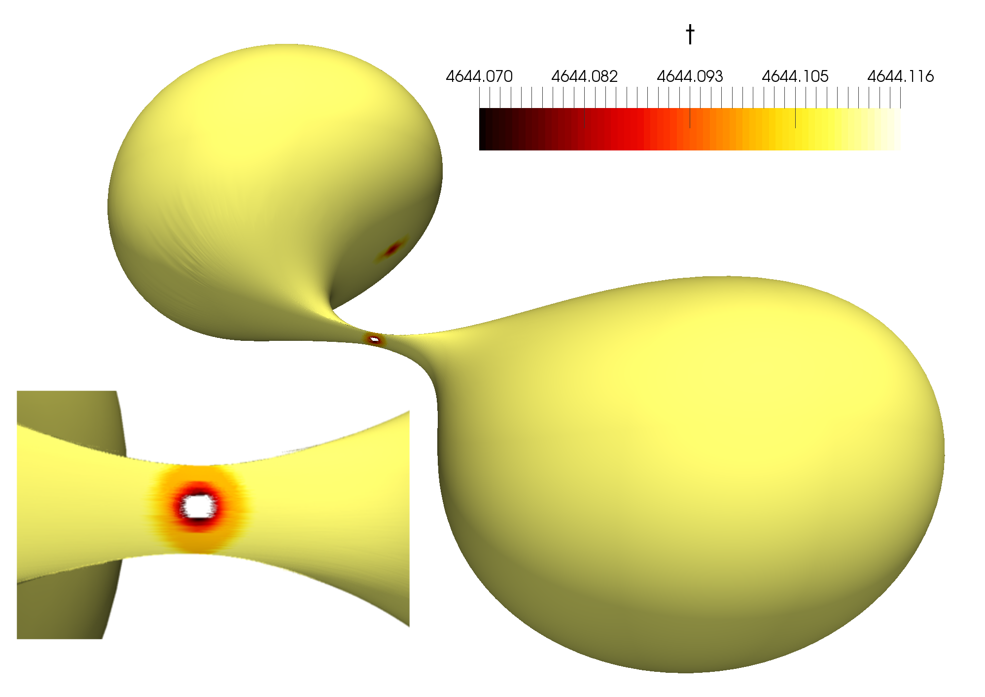
In this paper, we find that the topology of the event horizon for binary black hole (BBH) systems transitions from two spheres () to a single sphere () in the gauge used to merge the binary with the Spectral Einstein Code (SpEC) SpE ; Szilágyi et al. (2009); Hemberger et al. (2013); SXS (a), in agreement with previous results Cohen et al. (2012). However, the event horizon is a -dimensional hypersurface where the topology of the event horizon depends on the foliation of the spacetime Siino (1998a, b). When considering how future generators join the event horizon, the set of crossover points is known to live on a spacelike hypersurface that becomes asymptotically null as this hypersurface approaches a set of caustics Shapiro et al. (1995). Therefore there must exist a spacelike foliation that cuts a hole out of the spacelike surface of crossover points, resulting in a short-lived toroidal event horizon. We show explicitly that the event horizon topology can be toroidal () in a spacelike foliation of the spacetime, as shown in Fig. 1, by applying a coordinate transformation to the coordinate system used in SpEC to evolve the binary.
The organization of this paper is as follows: In Section II we present a coordinate transformation designed to find a new spacetime foliation where the event horizon has a toroidal topology. We begin in Section III.1 by studying a toy model horizon of a spherical wavefront in flat spacetime, where there are no crossovers. In Section III.2, we analyze a head-on BBH merger and find a future generator structure similar to the spherical wavefront model that prohibits the possibility of a toroidal event horizon in any spacelike foliation of the spacetime. However, in Section III.3 we show a toy model horizon of an ellipsoidal222Here “ellipsoidal” refers to an oblate ellipsoid that is not a coordinate sphere. wavefront in flat spacetime where the caustic and crossover distribution allows for a torodial reslicing. Utilizing what we learn with the ellipsoidal model, we are able to directly reslice an equal mass inspiral EH into a short-lived torus in Section III.4. Finally, in Section III.5, we show that a similar coordinate transformation of the EH can produce a “baby” event horizon that appears briefly during BBH mergers, before all three surfaces connect.
II Reslicing the event horizon
The binary black hole event horizons we simulated for this work do not show a toroidal topology using the SpEC time coordinate. However, the event horizon is a -dimensional hypersurface, and the simulation time coordinate describes only one possible spacelike foliation of the hypersurface. The generalized harmonic time slicing of our binary black hole simulations Lindblom et al. (2006) may not be conducive to producing toroidal event horizons Cohen et al. (2012, 2009). We specify in this section a coordinate transformation from the coordinate system of the BBH evolution to a new coordinate system to explore the possibility of another time slicing yielding a toroidal event horizon.
In the companion Bohn et al. (2016) to this paper, we introduce a complete replacement for the previous event horizon finding code in SpEC Cohen et al. (2009, 2012). The overall method is the same as before, where we evolve a set of event horizon generators backwards in time to trace out the horizon surface. At each time, we connect the generators together to form a polygon approximating a smooth surface with the topology of a sphere that may be self-intersecting. This surface does not approximate the event horizon only, but the union of the true event horizon and the locus of the future generators Thorne . The new event horizon finder is fully adaptive and so can resolve fine-scale features of the event horizon. This feature is crucial to demonstrating the existence of a toroidal topology.
 |
 |
 |
| (a) | (b) | (c) |
 |
 |
 |
| (d) | (e) | (f) |
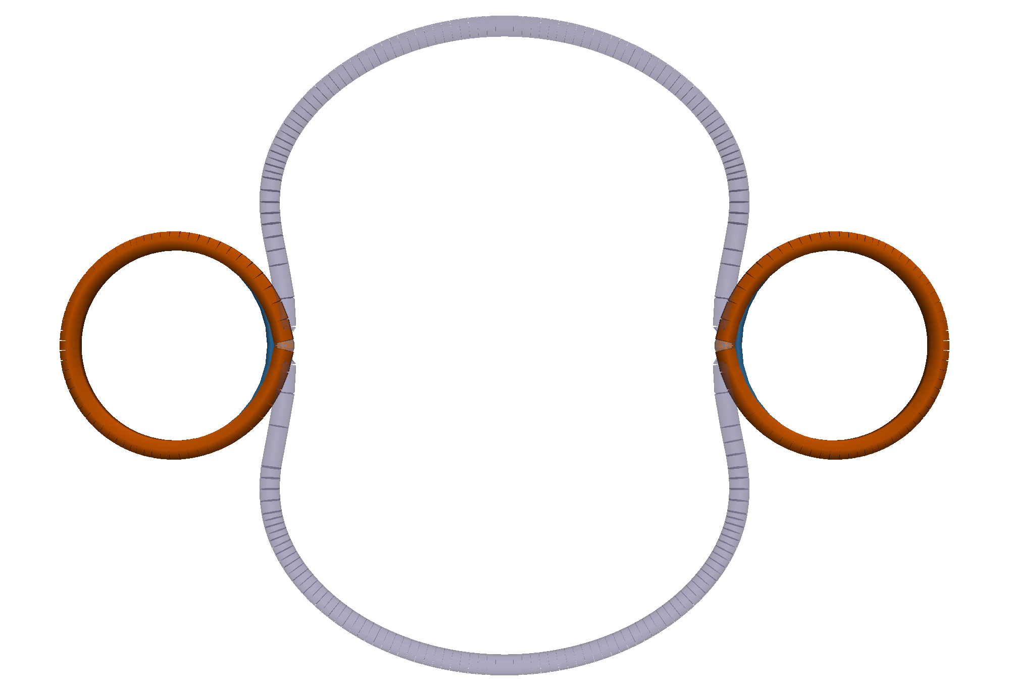
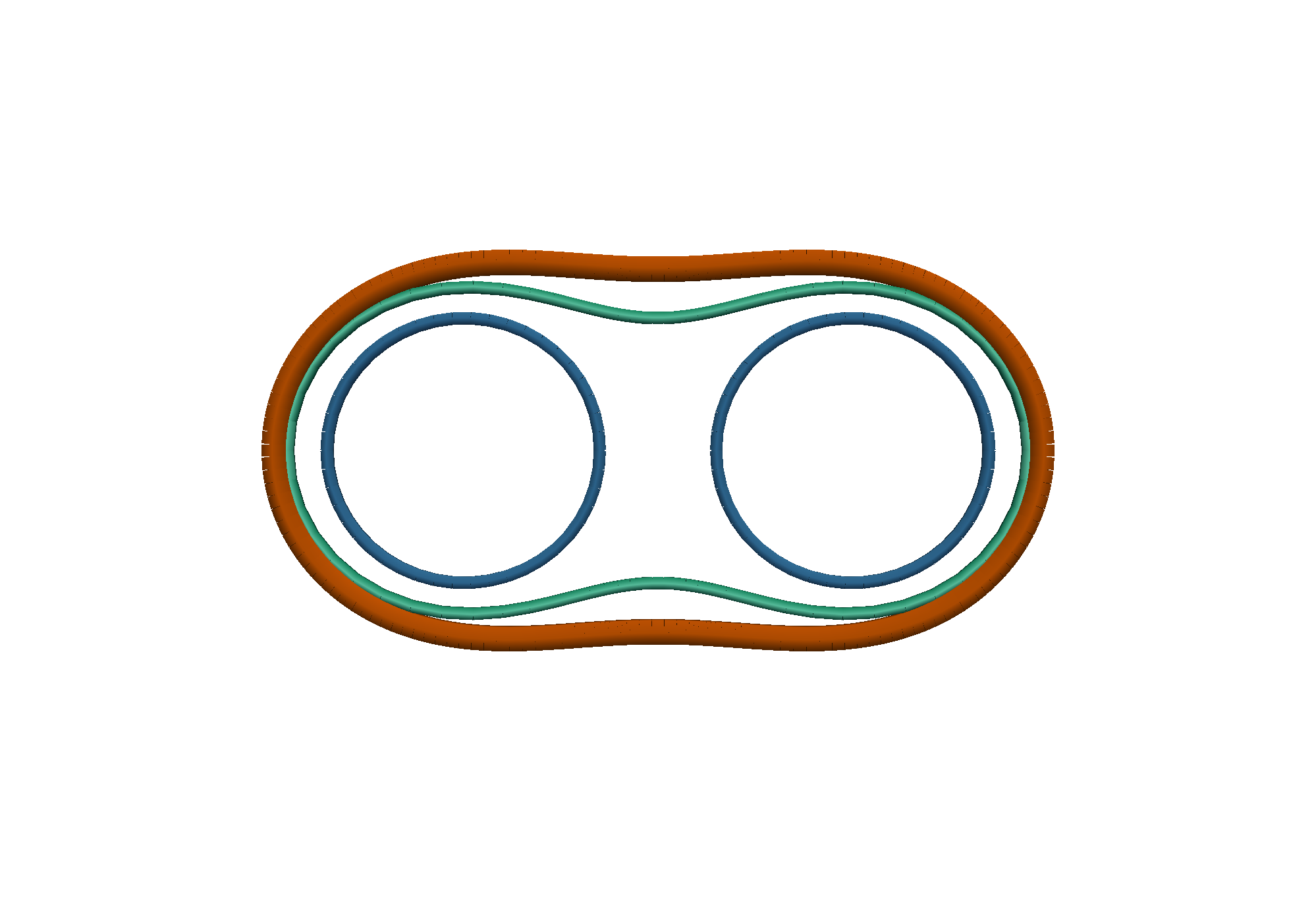
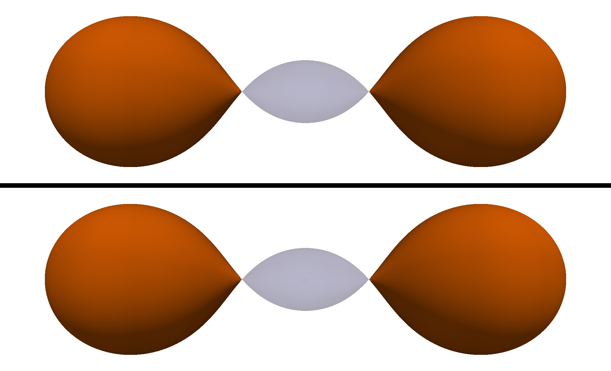
To make the discussion concrete, consider a head-on equal mass binary black hole merger, shown in Fig. 2. We see a spatial cross-section of apparent horizon surfaces shown blue or green, event horizon surfaces shown in orange, and the future generator surface shown in translucent purple. In panel (a), sufficiently long before the merger, the event horizon surfaces lie almost on top of the blue apparent horizon surfaces, which are hardly visible at this time. The future generator surface is comprised of future generators that will join onto the event horizon surface in the future. When rotating this panel about the rotational axis of symmetry, the union of the event horizon surfaces and future generator surface forms a smooth . In panel (b), shortly before the merger, the future generator surface is shrinking because some of the future generators have joined the event horizon between this time and the time of the previous panel. We can see the difference between the AH and EH surfaces increases as we get closer to the merger. There are no more future generators in panel (c) since they have all joined the event horizon surface, and therefore the event horizon surface must be Browdy and Galloway (1995).
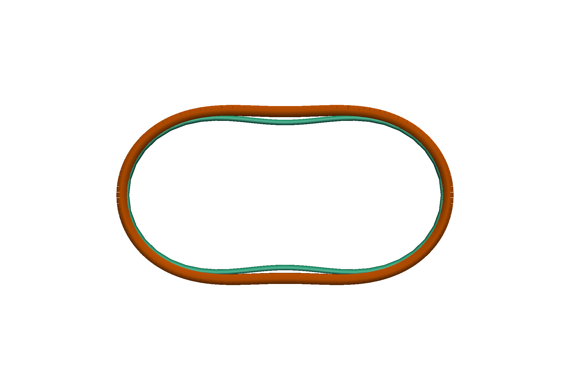
In panel (d), a common apparent horizon shown in green has formed around the two interior apparent horizons, and all three apparent horizons lie entirely on or within the event horizon, as they should. As time progresses to panels (e) and (f), we stop tracking the blue inner apparent horizons, the event horizon settles to a stationary state, and the common apparent horizon in green approaches the event horizon until the two surfaces eventually coincide. With this picture in mind, the method is to evolve generators backwards in time from panel (f) toward panel (a) which traces out the union of the event horizon surface with the future generator surface. Backwards in time, some generators “leave” the event horizon surface as seen in panels (b) and (a), so we must be able to identify which generators leave the surface and when they leave.
One of the shortcomings of our previous event horizon finder was the lack of flexibility to refine the distribution of event horizon generators in certain regions of interest. In the companion paper, we present a new method of distributing and maintaining a set of event horizon generators to address these issues. In particular, we now have the ability to study in much greater detail the region where future generators join the event horizon surface.
In Fig. 3, we show a dimensional representation of a BBH event horizon through merger. The slice is a constant slice through the event horizon at a time when the topology is two spheres, similar to panels (a) and (b) of Fig. 2. At this time, event horizon generators are joining the event horizon through, in general, both crossover points and caustics. Connecting the crossover points together forms a spacelike hypersurface denoted as , and connecting the caustic points forms spacelike hypersurfaces denoted as that form the boundary of the crossover region. Considering slices of constant in this example, the event horizon topology is never toroidal. However, a different spacelike slice could dip through to form a toroidal event horizon with a point in the middle of the hole. In essence, we are looking for a slice where generators in the crossover region are delayed near merger, similar to .
To accomplish this delay, we use a coordinate transformation of the form
| (1a) | ||||
| (1b) | ||||
where and are the coordinates after the transformation and is some smooth function of position and time. Equivalently, , such that a slice of constant is associated with a smaller value where is larger. Therefore, the value of controls how delayed generators at are in the constant slicing. An example of an event horizon on a constant slice is shown in Fig. 1, where the surface is colored by the associated value and generators near the hole in the event horizon correspond to earlier values.
The transformation has the Jacobian matrix
| (2) |
The normal to surfaces of constant is given by
| (3) |
where is the lapse in the barred coordinates. We can solve for from the normalization of the normal, , giving
| (4) |
where is the shift vector and is the three metric. The denominator of Eq. 4 must be greater than zero to obtain a foliation of the spacetime with spacelike hypersurfaces, since we know is greater than zero.
For the function , we choose a three-dimensional ellipsoidal Gaussian, with one dimension in time, one along a specified major axis, and the other in the minor plane perpendicular to the major axis. This gives free parameters to be specified: the amplitude (), the time center and time width ( and ), the spatial center (), the major axis direction (), and the major and minor widths ( and ). A two-dimensional example is shown in Fig. 4, where the time dimension has been omitted, and the plane perpendicular to has been projected down into one dimension. The function has the form
| (5) |
where the first exponential localizes the Gaussian to the time of merger, the second preferentially modifies geodesics along some major axis, and the third limits the range in the plane perpendicular to the major axis. The major axis is chosen in the thinnest direction of the small neck connecting the two black holes just after merger, which we will analyze in Section III.4. This choice produces time slices that cut through the spacelike crossover surface arising during the merger, as illustrated in Figs. 1 and 3. After finding Gaussian parameters that yield a toroidal event horizon on at least one constant slice, it is sufficient to verify that the new lapse is positive and real using Eq. 4.
To reslice the event horizon in practice, we first trace a set of generators to locate the EH in the generalized harmonic coordinate system used to merge the binary in SpEC, as detailed in the companion paper Bohn et al. (2016). During the generator evolution, we record the generator locations at a set of times that are finely spaced as the event horizons merge and coarsely spaced after the merger. Using Eq. 1b, we then calculate for each generator at each of these times. We want the locations of the generators on constant slices, and we accomplish this with a rd-order Lagrange interpolation polynomial in . The spacetime location where an EH generator joins the horizon is a spacetime event, so we simply apply the coordinate transformation to determine when the generator joins the horizon in the barred coordinate system.
III Discussion
Previous studies of merging event horizons infer the possibility of a toroidal event horizon by studying the distribution of caustics and crossover points during the merger. As discussed in Section II, the set of crossover points is known to live on a spacelike hypersurface that becomes asymptotically null as the surface approaches a set of caustics Shapiro et al. (1995). There should therefore exist a spacelike foliation of the spacetime that cuts a hole out of the spacelike surface of crossover points, resulting in a short-lived toroidal event horizon. In this section, we are interested in explicitly finding such a reslicing where the event horizon has a toroidal topology.
It is useful to first study null hypersurfaces in flat space, where the distribution of caustics and crossover points is known analytically. We will use these wavefronts as model horizons and refer to them as “horizons” for convenience in the spherical model in Section III.1 and in the ellipsoidal model in Section III.3. These models were introduced in Shapiro et al. Shapiro et al. (1995) and also studied in Siino Siino (1998a).
All of the systems in this discussion section can be found on the SXS collaboration website SXS (b) at the page EHT .
III.1 Spherical model
We trace generators for a spherical wavefront backwards in time through the Minkowski spacetime until all the generators leave the horizon through a caustic or a crossover point. These points are identified using the same algorithms as used for binary black hole event horizons, described in the methods paper Bohn et al. (2016). The initial data for this model horizon is a sphere of radius at , shown in Fig. 5, where the -axis is an axis of rotation. Generators are placed on the sphere pointing perpendicular to the surface outward and evolved backwards in time through flat space, where the black dashed arrows denote some generators of the horizon and the dotted teal lines show the corresponding generator trajectories. The generators begin the simulation on the surface and we search for caustics or crossover points to determine if and when generators leave the horizon backwards in time.
Because of the symmetry of the system, all future generators must join onto the horizon at the same location and time through a caustic, since all the generators meet together at the origin. The code properly labels all of the generators as joining through caustics and we do not find a surface of crossover points, as expected. The lack of a crossover surface makes this model illustrative for the head-on merger of equal mass black holes as featured in the following section.
Since there is no crossover surface, which would form a spacelike hypersurface, we should not expect to be able to find a slicing of the spacetime that yields a toroidal surface, so this provides a good test of our reslicing algorithm. Using the coordinate transformation in Section II with a flat metric and set large enough to keep the transformation independent of time, the new lapse from Eq. 4 simplifies to
| (6) |
We must therefore keep the spatial gradients of small to maintain a spacelike foliation. However, we know that any coordinate transformation will preserve events. In particular, the caustic event where all the generators meet at the origin of the coordinate system will be preserved, meaning all the generators will join the horizon at the same time in all foliations of the spacetime.
 |
 |
 |
| (a) | (b) | (c) |
Figure 6 shows this surface in two foliations of the spacetime, where the top row shows the original slicing with spherical initial data, and the bottom row shows the resliced horizon. It is important to reiterate that we will show horizons going forwards in time from left to right, but the generator evolution is performed backwards in time from right to left in these figures. Therefore, the initial data for the spherical model is in the top row of the rightmost panel. The bottom row is an attempt at a coordinate transformation into a new slicing of the spacetime to look for a torus.
Going along the top row from left to right, all the generators are initially future generators of the horizon, as indicated by the translucent purple color. As coordinate time progresses forward, all the generators meet together at a single point in time just before panel (b), where they join the surface through a caustic at the origin. The surface continues to expand linearly through panel (c) until reaching the unit sphere.
 |
 |
 |
 |
| (a) | (b) | (c) | (d) |
The bottom row paints a very similar picture, where we have applied the coordinate transformation in Eq. 1b to search for a toroidal topology. We tried a variety of parameters with similar results, but show the values from Case A of Table 1 for these figures. Just as in the original slicing, all the generators join at the same time through a caustic just before panel (b). The coordinate transformation changes the shape of the horizon, but leaves the topology unaffected.
| Case | |||||||
|---|---|---|---|---|---|---|---|
| A | |||||||
| B | |||||||
| C |
It is instructive to simplify horizons by taking a slice through the surface. In Fig. 7, we take a slice through the spherical model horizon along the major axis of the Gaussian coordinate transformation, such that a rotation of the slice produces the full surface in both coordinate systems. To analyze exactly how generators join the horizon, we have magnified the spatial and temporal scales relative to Fig. 6. Note that the rows show slices of constant time in different coordinate systems, so we do not expect events such as the joining of generators onto the horizon to align. In the top row, the generators join the horizon in panel (b) simultaneously at a single point, and similarly for the bottom row in panel (c).
Though the surfaces appear different in the two coordinate systems, we see clearly that the caustic event is preserved under coordinate transformation. Therefore the horizon of this model instantaneously transitions from not existing to having a spherical topology independent of the slicing as expected.
III.2 Equal mass head-on merger
The simplest binary black hole merger to study is the head-on merger of equal mass non-spinning black holes. The system we consider has black holes initially at rest centered at , where is the total mass of the black holes. This binary has rotational symmetry about the -axis connecting the two black holes as well as a mirror symmetry about the -plane halfway between the black holes. The expectation for the topology of this event horizon is two spheres before the merger that transition to a single sphere, with no toroidal phase in any slicing of the spacetime Massó et al. (1999); Lehner et al. (1999); Husa and Winicour (1999).
Straightforward symmetry arguments show that the event horizon topology must be composed of only spheres, as we now show. In this system, the resultant black hole after the merger settles down to a static Schwarzschild horizon since there is no angular momentum in the system about the origin. The initial data for the event horizon simulation is therefore a spherically symmetric surface. Consider the event horizon generators at the intersection between the EH and the mirror plane, forming a ring. The generators on this ring should initially look exactly like those in the spherical model shown in Fig. 5. These generators must remain in this plane for the entire simulation owing to the mirror symmetry. Furthermore, the spacetime is axisymmetric about the -axis, and so the generators must respect this symmetry and remain in a circle in this coordinate system. We can see from these symmetries that the generators in the mirror plane must all join simultaneously through a caustic at the origin, identical to the spherical model horizon in Section III.1. When considering planes where , the rotational symmetry still enforces that the intersection of the plane and the event horizon always remains circular, where all the generators in a circle similarly join the EH through a caustic along the -axis. We can parameterize all the future generators into rings by where along the -axis they join the EH. In any coordinate system, the generators in a given ring are either all future generators at a given time or all true generators of the EH. Because generators never cross after joining the EH surface, it is therefore impossible for a torus to form in any coordinate slicing of the head-on merger. Changing the number of EH surfaces is however possible with certain coordinate transformations that change the relative times when neighboring rings join the EH, as we will see in Section III.5.
Another way to state the argument is based on the lack of a crossover surface. The -dimensional event horizon hypersurface is null everywhere except for where future generators join the EH through caustics or crossover points, where it is spacelike. Using coordinate transformations, we can only cut a hole through the event horizon hypersurface where it is spacelike, along the inseam of the pair of pants in Fig. 3. We already argued that there are only caustics (and so no crossover points) in the coordinate system where the BBH system is axisymmetric, and that coordinate transformations preserve these caustics. The inseam of the pair of pants is thus -dimensional and composed of only caustics, and the rest of the event horizon hypersurface is null, therefore there is no -dimensional spacelike hypersurface through which to cut a hole in the EH.
 |
 |
 |
| (a) | (b) | (c) |
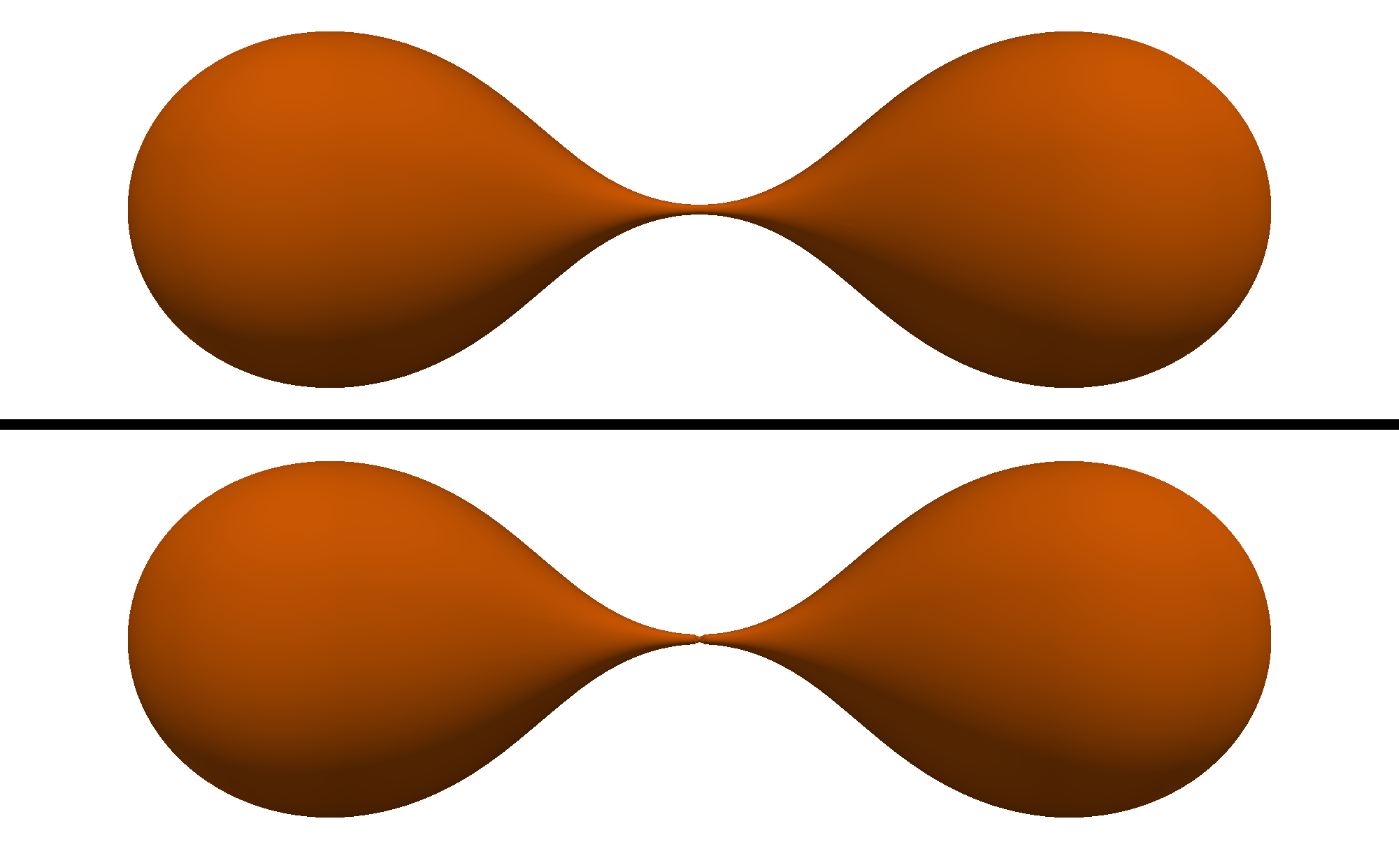
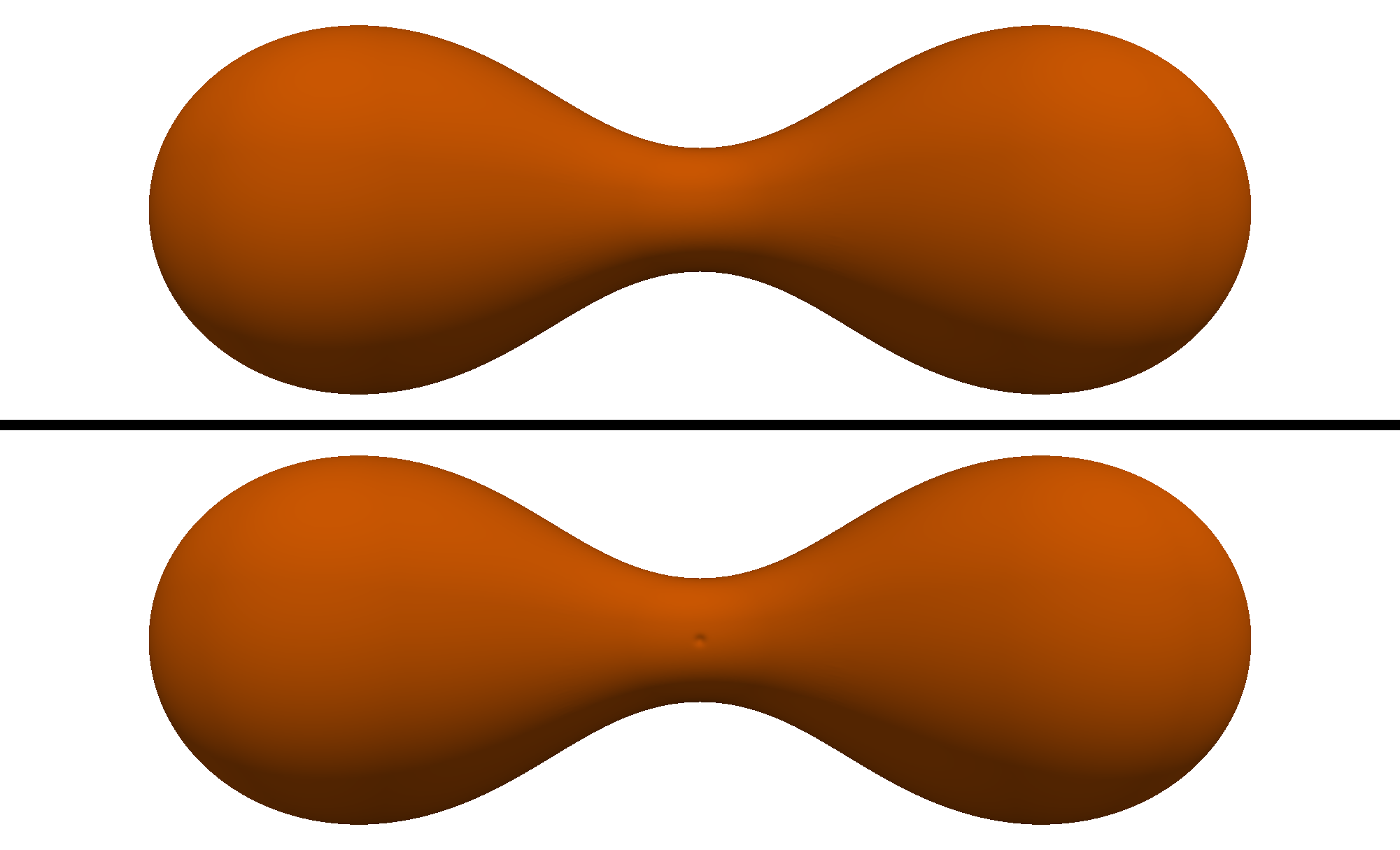
Figure 8 shows the event horizon surface before, during, and after the black hole merger. The parameters of the coordinate transformation are labeled Case B in Table 1. The event horizon in these two coordinate systems looks virtually indistinguishable because the spatial scale of the coordinate transformation is small compared to the scale of the figure. Topologically, both coordinate systems are identical. We have one spherical surface for each event horizon () in panel (a). After all the future generators join the EH, the horizon transitions into a single shown in panel (b) and remains that way.
 |
 |
 |
 |
| (a) | (b) | (c) | (d) |
Figure 9 shows spatial slices through the mirror symmetry plane. The top row shows the event horizon in the slicing used for the SpEC BBH spacetime evolution and the bottom row the transformed slicing. These slices look similar to slices of the spherical model shown in Fig. 7, where the coordinate slice in the top row remains a circle and generators on the circle join the horizon simultaneously through a caustic.
Just as in the spherical model, we cannot alter the relative timing of when the generators join the horizon in this slice, since these generators meet at a single event in spacetime, and coordinate transformations preserve events. We perform a reslicing anyway to illustrate the point and to test our code. In the bottom row of Fig. 9, we see small scale deformations along the top and bottom of the ring. Because of the coordinate transformation in Eq. 1b, generators in regions where is relatively large are delayed in the slicing, causing the small bumps in panels (a) and (d). The caustic event where generators join the horizon occurs in panel (c), showing that the caustic is preserved by the coordinate transformation. No hole in this event horizon could possibly exist because of the lack of a crossover surface.
Independent of the slicing of the spacetime, the head-on binary starts as a set of spheres and transitions to a single sphere. These results are consistent with the findings in Massó et al. (1999); Lehner et al. (1999); Husa and Winicour (1999), as well as the spherical model in Section III.1. The highest resolution of the SpEC BBH evolution was used for these figures, but the topological structure is the same in all three resolution levels of the SpEC evolution.
III.3 Ellipsoidal model
The prediction of Siino Siino (1998b) and Husa and Winicour Husa and Winicour (1999) is that toroidal event horizons should appear in generic BBH mergers, where there is no axis of symmetry. We analyze in this section an ellipsoidal wavefront, identical to the oblate spheroid model in Shapiro et al. (1995); Siino (1998a), that provides a more generic caustic and crossover distribution than the spherical wavefront model in Section III.1. The appearance of both caustics and crossovers makes this model illustrative for generic BBH mergers, such as the equal mass inspiral featured in the following section.
The initial data for the generator evolution is similar to the spherical model, but we place generators normal to the ellipsoid
| (7) |
shown in Fig. 10. Figure 11 shows this ellipsoidal horizon on a few time slices using the same color scheme and layout as Fig. 6. In agreement with Shapiro et al. Shapiro et al. (1995), the first generators to join the horizon join at the origin through crossover points in the top row of panel (c). The horizon is smooth everywhere, apart from a one-dimensional ring around the outside of the horizon where generators continue to join through crossover points. If we connect these crossover events to form a surface, we obtain a two-dimensional spacelike hypersurface in the equatorial plane (the -plane). Much later, the last future generators join the horizon along the outside ring in the equatorial plane, forming a one-dimensional ring of caustic events. This slicing therefore shows only a spherical topology.
 |
 |
 |
 |
| (a) | (b) | (c) | (d) |
The bottom row of Fig. 11 shows the horizon after the coordinate transformation in Eq. 1b with parameters identical to those used in the spherical model (case A of Table 1). While applying coordinate transformations will ensure that spacetime events such as caustic or crossover points are preserved, the relative time between neighboring caustic or crossover points can be altered. This coordinate transformation is sufficient to obtain a horizon that initially appears with a toroidal topology as shown in the bottom row of panel (c). The horizon is smooth apart from two one-dimensional rings where crossover generators continue to join the surface. One ring is on the outside of the torus and the other is on the inside. Shortly after the torus forms, the hole in the horizon closes, leaving the same spherical topology as seen in the top row of panel (c).
As we did for the spherical model, in Fig. 12 we take a slice through the horizon along the -axis to learn why it was possible to apply a coordinate transformation and obtain a torus. The spatial and temporal scales are magnified in this figure compared to Fig. 11 to showcase how the generators join the surface in both coordinate systems.
Panel (a) of Fig. 12 shows a slice of future generators with a quite different shape compared to what is seen in the spherical model. In the top row of panel (b), generators begin to join the horizon through crossover points, where generators from the top half of the slice meet the bottom half. The horizon instantaneously appears as an . In the slicing of the bottom row, the generators in the middle of the slice are delayed relative to their neighbors because of the positive Gaussian in the coordinate transformation. The delay is sufficient to cause the first generators that join the horizon to be spatially separated on the slice as seen in panel (c). After rotating about the vertical axis of symmetry, the surface initially appears with a toroidal topology. Finally, in the bottom row of panel (d), the interior region has closed to yield an topology. We have thus found a coordinate transformation that cuts a hole out of the spacelike crossover surface along the inseam.
III.4 Equal mass inspiral
The primary reason that the equal mass head-on merger did not yield a toroidal event horizon is the rotational symmetry of the system causing all the future generators to join the horizon through caustics. A binary black hole system in a quasi-circular orbit removes this rotational symmetry. We expect to see a more generic distribution of caustics and crossover points similar to the ellipsoidal model, enabling us to reslice the EH into a torus. For simplicity, we analyze a pair of non-spinning black holes, initially in a quasi-circular orbit with a separation of .
 |
 |
 |
| (a) | (b) | (c) |
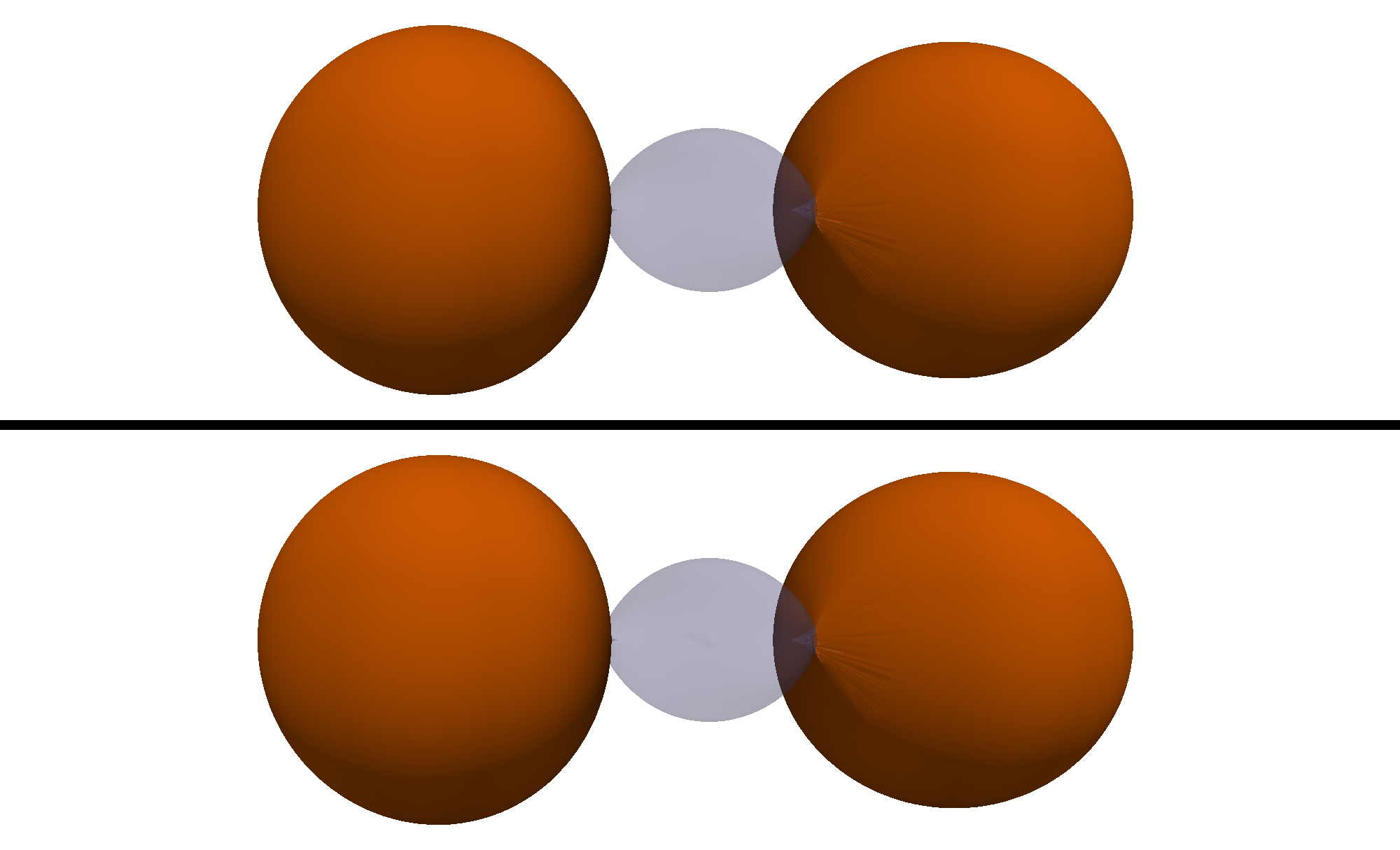
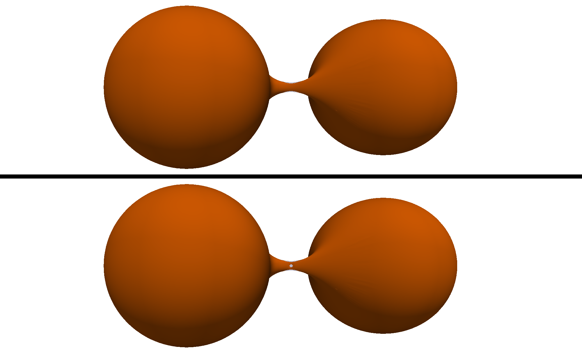
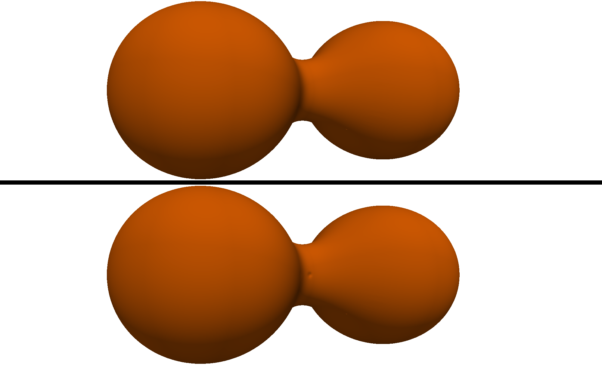
We show the event horizon surfaces in Fig. 13, where the camera is in the orbital plane and the orbital angular momentum of the system is pointing up. The coordinate transformation uses parameters with the label Case C in Table 1, and the amplitude is yet again quite small compared to the figure size. The time and space centers, and , are chosen to coincide with the location where the event horizons first meet. In this BBH, the neck joining the event horizons has an elliptical shape, similar to what was seen in the slices of the ellipsoidal model horizon. We learned from the ellipsoidal model that the direction of the major axis should be chosen roughly along the direction in which the crossover generators were traveling as they joined the horizon. The final parameter that is important to tune is the width of the Gaussian perpendicular to , , such that it is smaller than the width of the neck connecting the horizons.
 |
 |
| (a) pointing upward | (b) pointing out of the page |
Figure 14 shows a cartoon illustration of this coordinate transformation overlaid on the event horizon in barred coordinate system. The camera viewpoints are chosen such that in panel (a), is pointing up, and in panel (b), is pointing into the page. The major axis Gaussian width is not shown to scale in this figure, but the precise value of has little effect on the coordinate transformation once it is sufficiently large. In panel (a) the effect of the coordinate transformation is only to pinch the neck in the coordinate system in the region where the Gaussian is different than zero. The minor axis Gaussian width has most of the control over the size of the hole, where a smaller width causes a smaller (and thus harder to resolve numerically) hole. Smaller values of also result in sharper gradients of the function , which can cause the new lapse in Eq. 4 to become imaginary. However, a minor axis width that is too large gives a shallower gradient of the function , which could result in the lack of a toroidal horizon.
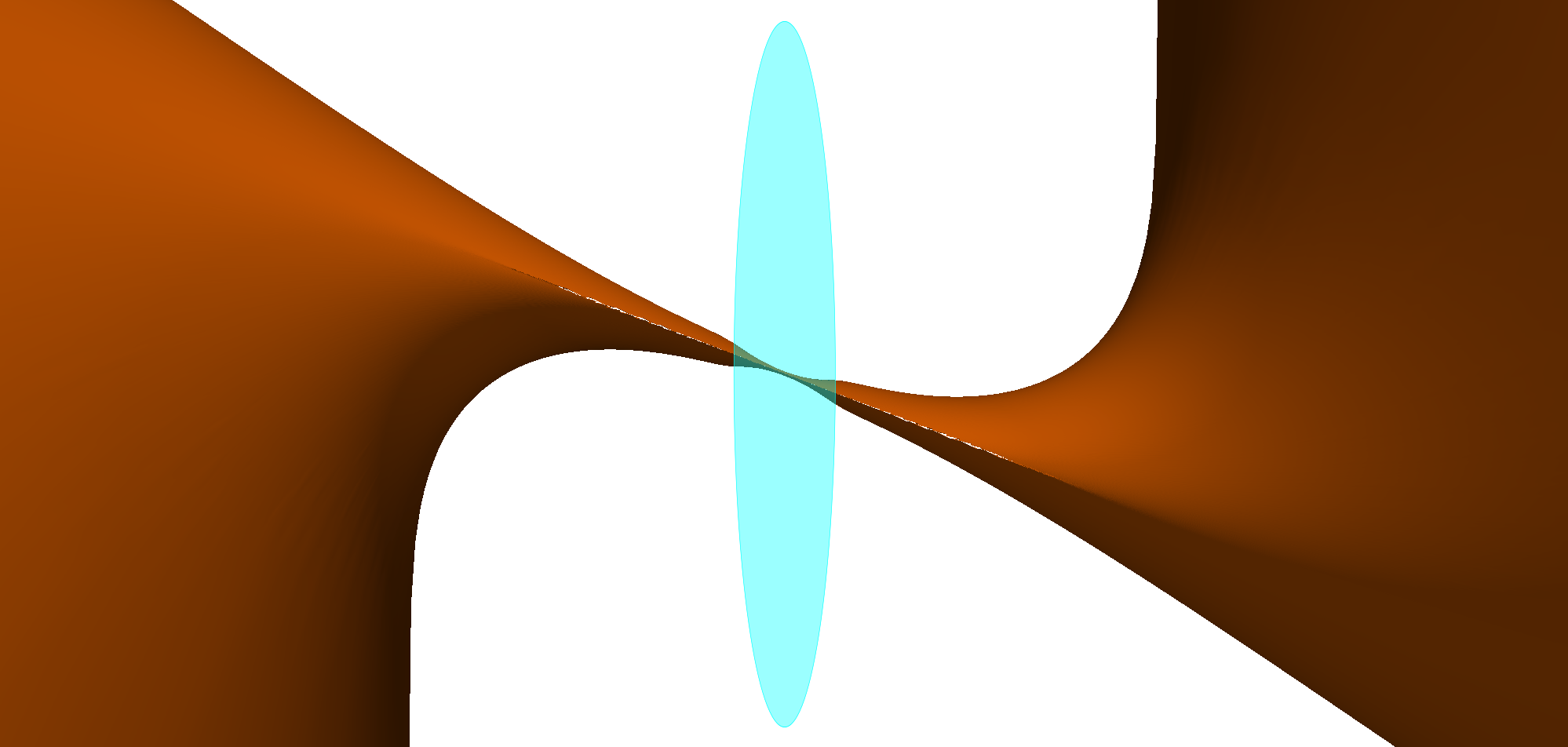
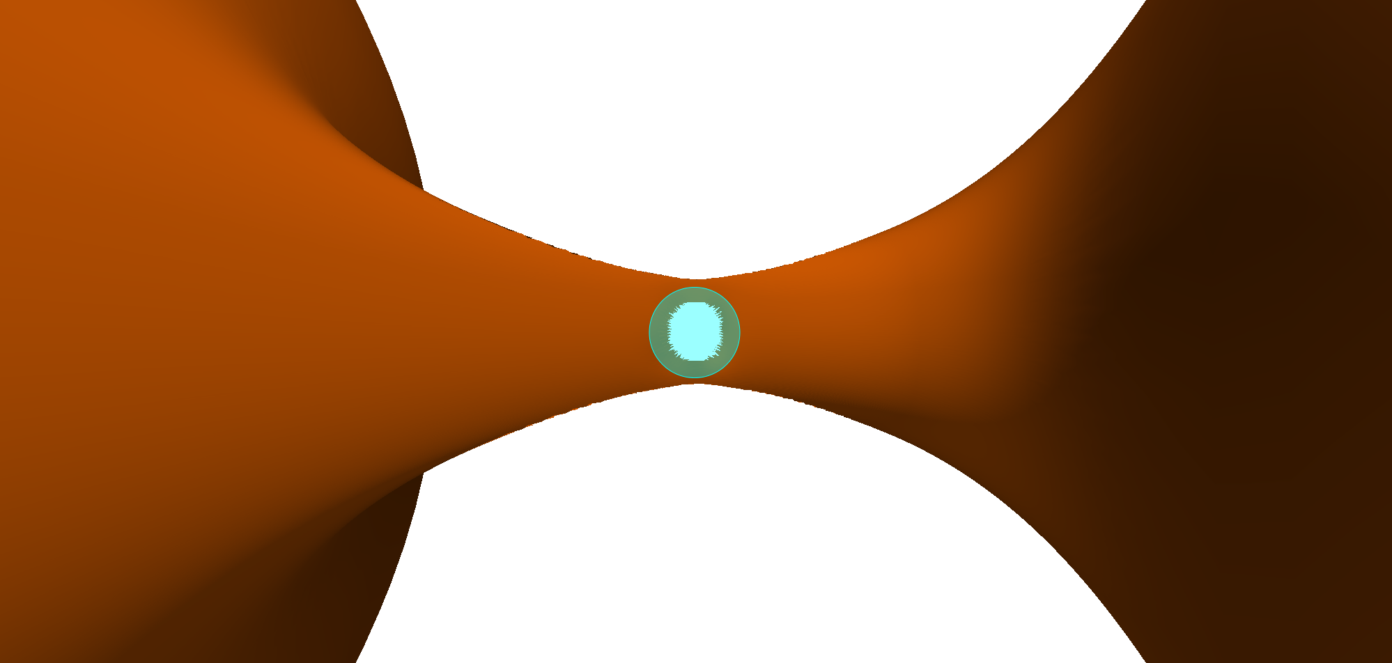
The torus is illuminated more clearly by taking spatial cuts through the EH surface in both coordinate systems as shown in Fig. 15. The vertical direction in the figure is parallel to . The slices in this figure bear a remarkable resemblance to the ellipsoidal model slices in Fig. 12, suggesting that the future generators join the horizon in a similar manner. In panel (b), the first generators to join the EH in the constant slicing join through crossover points. We are able to delay these generators such that the first generators to join the horizon in the constant slicing are spatially separated in the slice in panel (c). As time progresses forward, generators continue to join at the interfaces between future generators and event horizon regions in the slicing. Finally in panel (d), the two pieces of the horizon connect after all the remaining generators in the gap join the horizon.
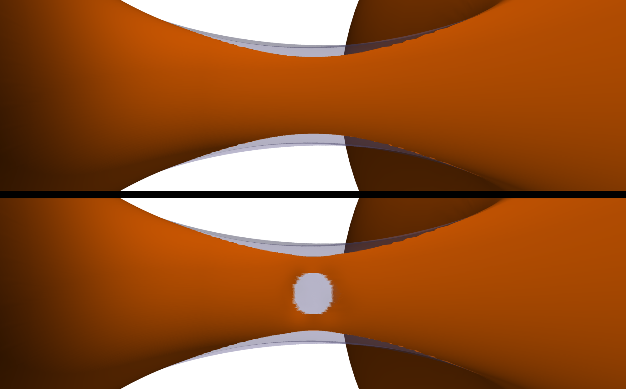
Figure 16 shows up close what the hole in the horizon looks like. The top and bottom rows are constant and constant slices. We are showing both the full generator surface as well as the same spatial slice as seen in panel (c) of Fig. 15. The constant slice shows clearly that there is a hole in the event horizon surface, so the EH has a toroidal topology. For the hole in the horizon, the EH surface pinches off along a one-dimensional non-smooth ring where event horizon generators will continue to join through crossover points. The left and right edges of the event horizon surface shown in orange are also not smooth, where generators continue to join through crossover points. The final generators to join the event horizon surface do so through caustic events, just as seen in the ellipsoidal model (Fig. 12). This torus is seen in all three refinement levels of the SpEC BBH evolution.
 |
 |
 |
 |
| (a) | (b) | (c) | (d) |
The coordinate transformation used does not guarantee that constant hypersurfaces are spacelike. We therefore must check that the new lapse is well behaved by evaluating Eq. 4 in the region where differs from , that is, where is non-negligible. We construct a grid of points centered about and to evaluate the new lapse in the range of
| (8a) | ||||
| (8b) | ||||
where and are unit vectors perpendicular to each other and perpendicular to . Beyond this range, the Gaussian function is vanishingly small () for our purposes.
We use a grid of points with points distributed in each dimension of the four-dimensional space defined by Eq. 8b to calculate the new lapse and check that it is real. Because the new lapse is a function of the metric in the SpEC coordinate system, we must interpolate the metric to the location in space and time where is to be calculated. These interpolations are performed the same way as is done during the generator evolution, described in the companion paper Bohn et al. (2016).

Figure 17 shows the lapse squared in both the SpEC coordinate system () and in the new coordinate system () using a grid with evenly distributed points over the Gaussian. At each of the times, we calculate the square of the lapse on spatial points and plot the maximum and minimum found in both coordinate systems. This plot shows that the constant hypersurfaces are indeed spacelike, because is positive at all times. It should be noted that we could not check the lapse at all points on this wide grid, since some of the points live off the SpEC evolution domain because of the excision region inside the black holes; However, these locations are guaranteed to be inside the event horizon and so do not affect the event horizon. All other points in the SpEC domain and in the space defined by Eq. 8b contribute to Fig. 17. The large spike in the minimum lapse squared in both coordinate systems is an expected feature from how the excision surfaces in SpEC change during the BBH merger phase.
III.5 Baby event horizons
To obtain toroidal event horizons, we used a positive amplitude Gaussian in our coordinate transformation in Eq. 1b to delay generators in a small region around where the event horizons merge. We now consider the effect of a negative amplitude Gaussian that will advance generators in a small region.
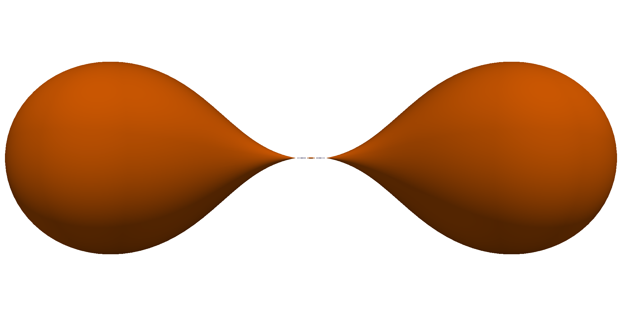
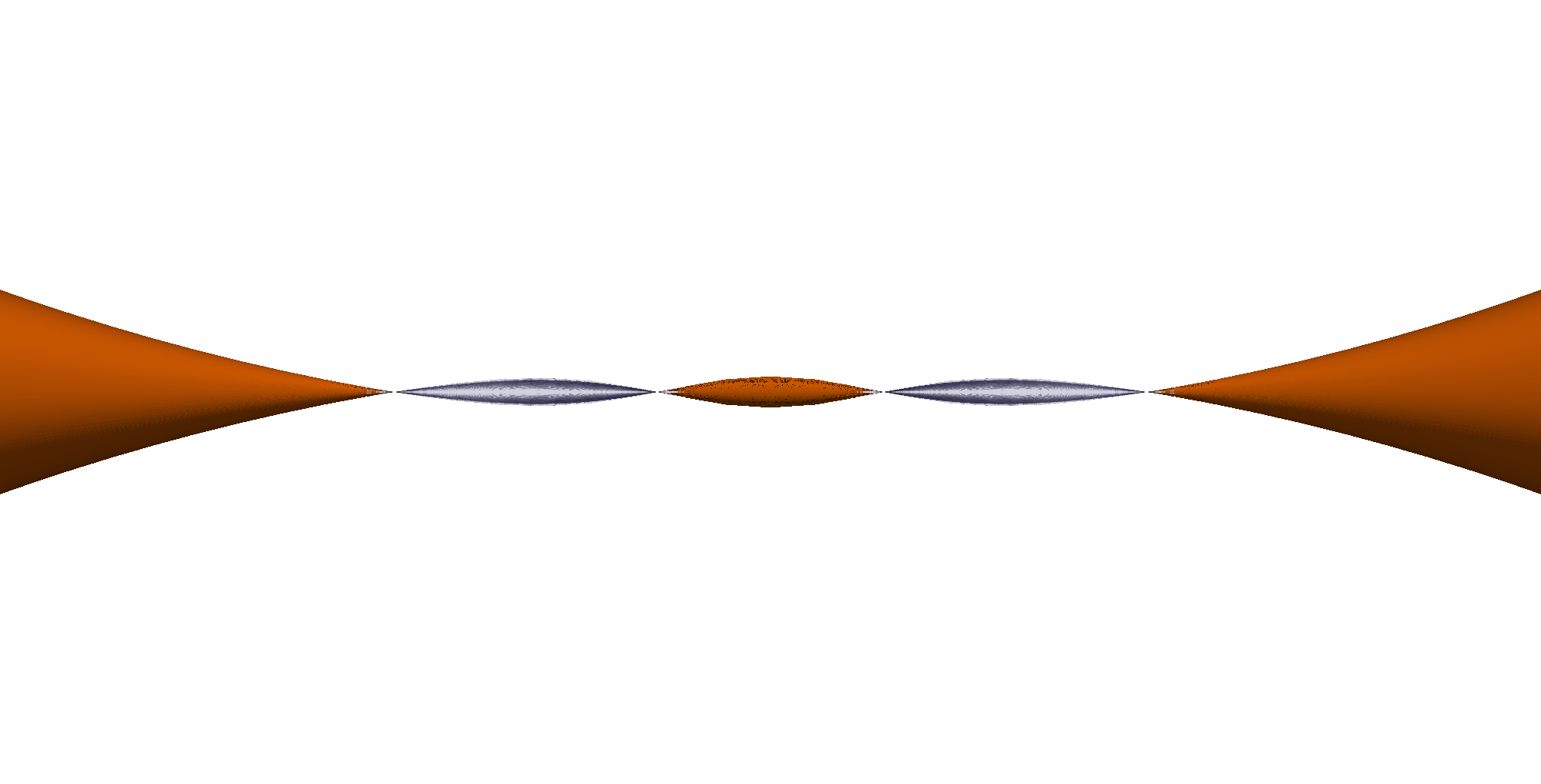
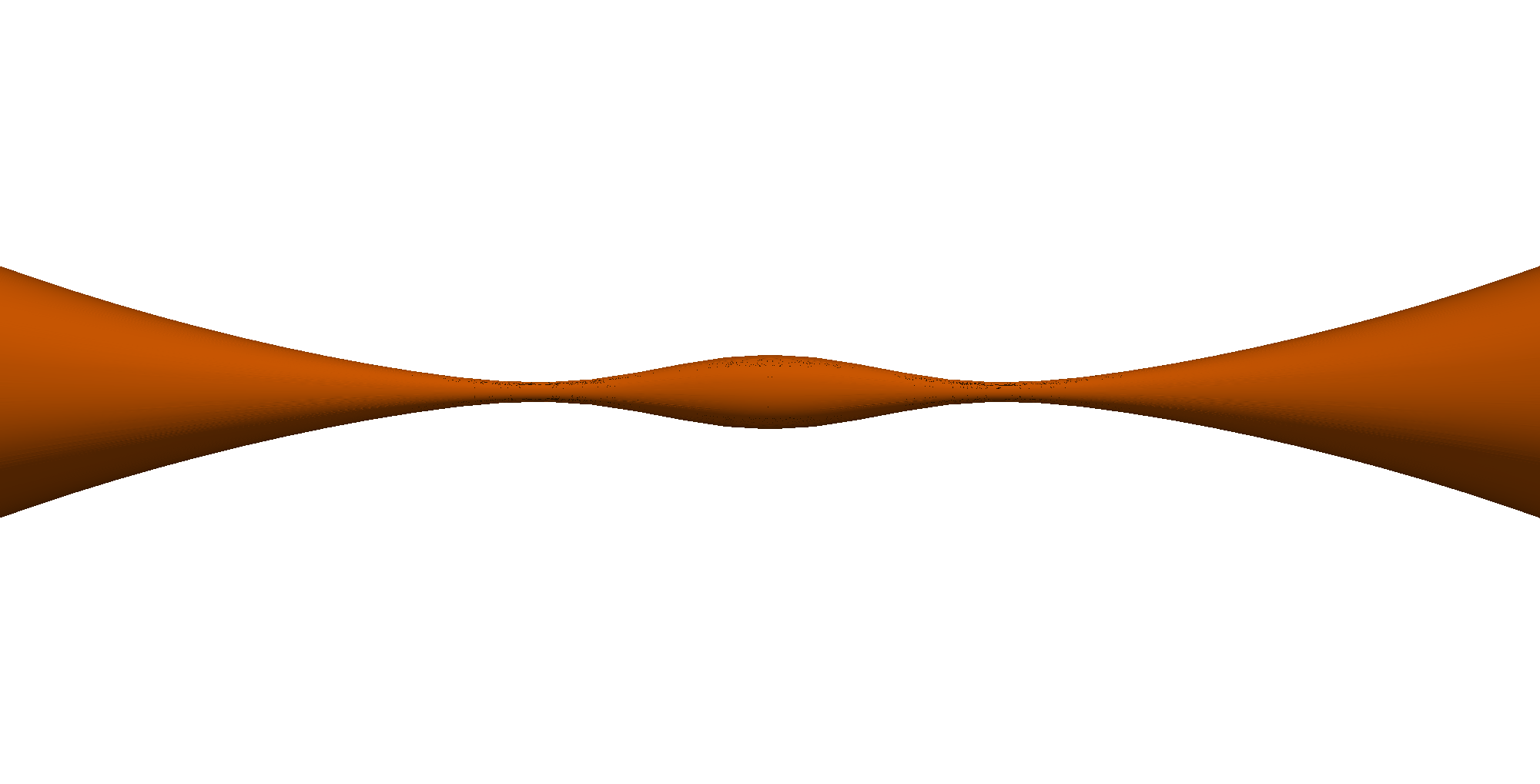
The head-on BBH event horizon from Section III.2 has all the future generators joining through caustics that form a one-dimensional spacelike line along the inseam of the pair of pants diagram. If we advance generators in a small region near this line, we can push the time slice across this spacelike line in a small region. The event horizon on the new time slice would have the topology of three spheres instead of before the merger. In theory, we could make our time slicing cross the spacelike line of caustics as many times as we would like to create a topology of , a possibility proved by Siino Siino (1998b) in corollary III.8. This is directly demonstrated in Fig. 18. We have also created an additional “baby” event horizon in more generic mergers such as the binary in Fig. 1, where there are not only caustics but also crossover points.
 |
 |
 |
| (a) : Zoomed out | (b) | (c) |
Similarly, when we can reslice an event horizon to produce a torus with one hole, we can reslice into a torus with holes. The crossover surface is spacelike, so we can construct a slicing that intersects this crossover surface an arbitrary number of times.
IV Conclusions
Siino Siino (1998b) and Husa and Winicour Husa and Winicour (1999) expected that merging black hole event horizons should generically have a brief toroidal topology. While simulations of rotating collapsing matter have shown event horizons that appear initially with a toroidal topology, the toroidal BBH event horizon has remained hidden during numerical simulations. While the -dimensional event horizon hypersurface itself does not depend on the spacetime foliation, the choice of spacetime foliation does affect the topology of the EH on the slice. For the case of the inspiral and merger of two equal mass non-spinning black holes, we find the event horizon topology transitions directly from two spheres to one sphere in the SpEC coordinate slicing. However, we show directly that a toroidal event horizon is possible through the use of a specially constructed coordinate transformation. The topology of the event horizon in the new coordinate system transitions from two spheres to a short-lived torus before transitioning finally to one sphere. No event horizons of merging black holes prior to this paper have yielded a toroidal topology Cohen et al. (2012, 2009); Diener (2003); Ponce et al. (2011).
We believe that our reslicing method can be applied to the merger of any black holes with sufficient asymmetry (i.e., not including a head-on merger of black holes where the symmetry prevents the possibility of a torus). Previous work has numerically found a surface of crossover points during the merger, where generators meet non-neighboring generators as they join the EH surface. Because this surface of crossover points is spacelike, we can apply our coordinate transformation to “cut a hole” through the crossover surface, while keeping the hypersurfaces of constant time spacelike. We therefore agree with Siino Siino (1998b) and Husa and Winicour Husa and Winicour (1999) that merging black holes should, in general, briefly have a toroidal event horizon topology, with the caveat that the torus may only exist in some foliations of the spacetime. It is interesting that Siino and Husa and Winicour predict tori generically, and expect slicings where there is no torus to be an exception to the rule. It is therefore somewhat surprising that in the time slicing used in SpEC and all other numerical codes, it appears that slicings with a toroidal event horizon are the exception to the rule.
As for topological censorship, because we are explicitly converting a spherical event horizon into a toroidal event horizon with our coordinate transformation, we are satisfying topological censorship by construction. That is, we can trivially reslice the event horizon back into a spherical topology, removing the topological torus, implying that the hole in the event horizon closes faster than the speed of light. Therefore a photon that appears to probe the topology of the spacetime by passing through the hole in the EH in one foliation of the spacetime will simply pass between the event horizons before they merge in another foliation. We note that while it is true one can always reslice a topological-censorship-satisfying torus into a sphere, the reverse is not always true.
Acknowledgements.
We thank Aaron Zimmerman for the suggestion of using a negative amplitude Gaussian to create a baby event horizon, and for helpful dialogues regarding topologies of event horizon surfaces. For ongoing feedback and suggestions for finding toroidal event horizons over the past few years, we thank Jeffrey Winicour. We also thank Michael Boyle for useful conversations about topologies of event horizon surfaces and useful paper comments. We thank Leo C. Stein for verifying the effects of coordinate transformations and useful paper comments. For keeping the SpEC code from changing under us while we were locating event horizons, we thank Daniel A. Hemberger. We are grateful to Jordan Moxon, Nils Deppe, and François Hébert for time slicing conversations and useful comments during the editing phase of this paper. We also thank Harald Pfeiffer for providing the BBH simulation with parameters similar to the system detected by Advanced LIGO. For helping smooth the visualization of event horizon surfaces, we thank Curran D. Muhlberger. We gratefully acknowledge support for this research at Cornell from the Sherman Fairchild Foundation and NSF grants PHY-1306125 and AST-1333129. Calculations were performed on the Zwicky cluster at Caltech, which is supported by the Sherman Fairchild Foundation and by NSF award PHY-0960291; on the NFS XSEDE network under grant TG-PHY990007N; at the GPC supercomputer at the SciNet HPC Consortium Loken et al. (2010); SciNet is funded by: the Canada Foundation for Innovation (CFI) under the auspices of Compute Canada; the Government of Ontario; Ontario Research Fund (ORF) – Research Excellence; and the University of Toronto. All the surface visualizations were done using Paraview par . The line plots were produced using the Matplotlib Hunter (2007) library with Python.References
- Hawking and Ellis (1973) S. W. Hawking and G. F. R. Ellis, The Large Scale Structure of Space-time (Cambridge University Press, Cambridge, England, 1973).
- Hawking (1972) S. W. Hawking, Commun. Math. Phys. 25, 152 (1972).
- Chrusciel and Wald (1994) P. T. Chrusciel and R. M. Wald, Class. Quantum Grav. 11, L147 (1994).
- Gannon (1976) D. Gannon, Gen. Relativ. Gravit. 7, 219 (1976).
- Friedman et al. (1993) J. L. Friedman, K. Schleich, and D. M. Witt, Phys. Rev. Lett. 71, 1486 (1993), erratum: Friedman et al. (1995).
- Galloway (1995) G. J. Galloway, Class. Quantum Grav. 12, L99 (1995).
- Jacobson and Venkataramani (1995) T. Jacobson and S. Venkataramani, Class. Quantum Grav. 12, 1055 (1995).
- Siino (1998a) M. Siino, Progress of Theoretical Physics 99, 1 (1998a).
- Siino (1998b) M. Siino, Phys. Rev. D 58, 104016 (1998b).
- Hughes et al. (1994) S. A. Hughes, C. R. Keeton, P. Walker, K. T. Walsh, S. L. Shapiro, and S. A. Teukolsky, Phys. Rev. D 49, 4004 (1994).
- Shapiro et al. (1995) S. L. Shapiro, S. A. Teukolsky, and J. Winicour, Phys. Rev. D 52, 6982 (1995).
- Husa and Winicour (1999) S. Husa and J. Winicour, Phys. Rev. D 60, 084019 (1999), gr-qc/9905039 .
- Hatcher (2001) A. Hatcher, Algebraic Topology, 1st ed. (Cambridge University Press, New York, NY, 2001).
- Cohen et al. (2012) M. I. Cohen, J. D. Kaplan, and M. A. Scheel, Phys. Rev. D 85, 024031 (2012), arXiv:1110.1668 [gr-qc] .
- Diener (2003) P. Diener, Class. Quantum Grav. 20, 4901 (2003).
- Ponce et al. (2011) M. Ponce, C. Lousto, and Y. Zlochower, Class. Quantum Grav. 28, 145027 (2011), arXiv:1008.2761 [gr-qc] .
- Abbott et al. (2016) B. P. Abbott et al. (Virgo, LIGO Scientific), Phys. Rev. Lett. 116, 061102 (2016), arXiv:1602.03837 [gr-qc] .
- Penrose (1968) R. Penrose, pp 121-235 of Battelle Rencontres. DeWitt, Cecile M. (ed.). New York W. A. Benjamin, Inc. (1968).
- Wald (1984) R. M. Wald, General Relativity (University of Chicago Press, Chicago, IL, 1984).
- Anninos et al. (1995) P. Anninos, D. Bernstein, S. Brandt, J. Libson, J. Massó, E. Seidel, L. Smarr, W.-M. Suen, and P. Walker, Phys. Rev. Lett. 74, 630 (1995).
- Shapiro and Teukolsky (1980) S. L. Shapiro and S. A. Teukolsky, Astrophys. J. 235, 199 (1980).
- Libson et al. (1996) J. Libson, J. Massó, E. Seidel, W.-M. Suen, and P. Walker, Phys. Rev. D53, 4335 (1996).
- Cohen et al. (2009) M. Cohen, H. P. Pfeiffer, and M. A. Scheel, Class. Quantum Grav. 26, 035005 (2009), arXiv:0809.2628 .
- Lehner et al. (1999) L. Lehner, N. Bishop, R. Gomez, B. Szilágyi, and J. Winicour, Phys. Rev. D 60, 044005 (1999), arXiv:9809034 [gr-qc] .
- Browdy and Galloway (1995) S. Browdy and G. Galloway, J. Math. Phys. 36, 4952 (1995).
- (26) http://www.black-holes.org/SpEC.html.
- Szilágyi et al. (2009) B. Szilágyi, L. Lindblom, and M. A. Scheel, Phys. Rev. D 80, 124010 (2009), arXiv:0909.3557 [gr-qc] .
- Hemberger et al. (2013) D. A. Hemberger, M. A. Scheel, L. E. Kidder, B. Szilágyi, G. Lovelace, N. W. Taylor, and S. A. Teukolsky, Class. Quantum Grav. 30, 115001 (2013), arXiv:1211.6079 [gr-qc] .
- SXS (a) http://www.black-holes.org/waveforms (a).
- Lindblom et al. (2006) L. Lindblom, M. A. Scheel, L. E. Kidder, R. Owen, and O. Rinne, Class. Quantum Grav. 23, 447 (2006), gr-qc/0512093 .
- Bohn et al. (2016) A. Bohn, L. E. Kidder, and S. A. Teukolsky, (2016).
- (32) K. Thorne, Suggestion to the authors of Anninos et al. (1995); Libson et al. (1996) that the locus of all event horizon generators forms at all times a smooth and sometimes self-intersecting surface.
- SXS (b) “Simulating eXtreme Spacetimes,” (b), http://www.black-holes.org/.
- (34) “Website with supplementary event horizon topology videos,” https://www.black-holes.org/for-researchers/event-horizon-topologies.
- Massó et al. (1999) J. Massó, E. Seidel, W.-M. Suen, and P. Walker, Phys. Rev. D 59, 064015 (1999).
- Loken et al. (2010) C. Loken, D. Gruner, L. Groer, R. Peltier, N. Bunn, M. Craig, T. Henriques, J. Dempsey, C.-H. Yu, J. Chen, L. J. Dursi, J. Chong, S. Northrup, J. Pinto, N. Knecht, and R. V. Zon, J. Phys.: Conf. Ser. 256, 012026 (2010).
- (37) “ParaView - open source scientific visualization,” http://www.paraview.org/.
- Hunter (2007) J. D. Hunter, Comput. Sci. Eng. 9, 90 (2007).
- Friedman et al. (1995) J. L. Friedman, K. Schleich, and D. M. Witt, Phys. Rev. Lett. 75, 1872 (1995).


