RCFD: A Frequency–Based Channel Access
Scheme
for
Full–Duplex
Wireless Networks
Abstract
Recently, several working implementations of in–band full–duplex wireless systems have been presented, where the same node can transmit and receive simultaneously in the same frequency band. The introduction of such a possibility at the physical layer could lead to improved performance but also poses several challenges at the MAC layer. In this paper, an innovative mechanism of channel contention in full–duplex OFDM wireless networks is proposed. This strategy is able to ensure efficient transmission scheduling with the result of avoiding collisions and effectively exploiting full–duplex opportunities. As a consequence, considerable performance improvements are observed with respect to standard and state–of–the–art MAC protocols for wireless networks, as highlighted by extensive simulations performed in ad hoc wireless networks with varying number of nodes.
I Introduction
The currently employed channel access strategies in wireless networks provide good performance, namely high data rates and low latency, while ensuring acceptable fairness to all the users. However, they still suffer from some issues, such as the hidden and exposed terminal problems. One of the most important limitations of wireless networks, with respect to wired solutions, is the so–called “half–duplex constraint,” i.e., the impossibility to transmit and receive in the same frequency band at the same time. The main challenge in obtaining full–duplex (FD) communication is the self–interference (SI) that affects the receive chain when transmission and reception occur simultaneously. The power of the signal emitted by a given node at its own receiver is much higher than that received from any other node, simply because the former comes from a much nearer source, with the result of completely destroying the signal of interest and prevent its successful decoding.
Recently, many research groups reported different implementations of self–interference cancellation schemes [1, 2], in order to eliminate the impact of the SI signal on the receiver and enable simultaneous transmission and reception in the same frequency band. These findings opened the way for a new branch of research, concerned with redesigning the higher layers of wireless networks in order to fully exploit these new FD capabilities. In particular, the definition of MAC layer strategies able to take advantage of such new features is a topic of great interest. Although numerous schemes have already been proposed, for a variety of network architectures [3, 4, 5], all of them present specific benefits and drawbacks and no proposal has emerged as the leading one for the definition of a future FD MAC layer protocol. It has to be remarked that the possibility for a node to receive and transmit at the same time, although allowing a potential doubling of the network capacity, increases the nodes exposition to interference and considerably complicates the scheduling of transmissions. The study of channel access schemes capable of efficiently exploiting the FD capabilities and producing significant performance gains compared to current wireless systems is, consequently, a very important research topic.
Another direction of research that aims at overcoming the limitations of standard, time–domain based, distributed channel access schemes for wireless networks relies on the idea of moving the entire channel contention procedure to the frequency domain [6]. The proposed solution exploits the availability of multiple subcarriers (SCs), derived from the common adoption of Orthogonal Frequency–Division Multiplexing (OFDM) modulation in modern wireless networks, and lets the nodes contend for the channel by randomly selecting one of these SCs. This innovative approach allows to solve contention in a short amount of time compared to traditional time–domain schemes, such as the Carrier Sense Multiple Access with Collision Avoidance (CSMA/CA) adopted in IEEE 802.11 networks. However, it faces some limitations and, in particular, appears to be unsuitable for the realistic case of a network with multiple contention domains. With the term collision (or contention) domain of a node, we refer to the set of nodes in the network that are within its coverage area. In a network with a single collision domain, the coverage area of each node includes all the other nodes in the network, whereas in the case of multiple collision domains, nodes have different coverage areas.
In this paper, we revisit the frequency–domain contention approach and propose a new channel access algorithm able to efficiently schedule transmissions in a context where nodes are equipped with FD capabilities. The scheme works in general ad hoc wireless networks, is fully distributed, preserves the desired randomness thus ensuring fairness among different nodes, and is not affected by the presence of several contention domains. Indeed, multiple contention rounds in the frequency domain, each corresponding to an OFDM symbol, are used to advertise the transmission intentions of the nodes and to select the pair of nodes that will actually perform a data exchange within a single collision domain. Since this approach resembles the Request To Send/Clear To Send (RTS/CTS) scheme designed for IEEE 802.11 networks [7], we called the new MAC layer scheme as RTS/CTS in the Frequency Domain (RCFD). Such an approach eliminates some of the problems that traditionally affect wireless networks, for example the hidden terminal (HT) issue.
The rest of the paper is organized as follows. Section II presents the state–of–the–art on the topics discussed in this paper and introduces some general concepts. The structure of the proposed RCFD MAC protocol is given in Section III, together with some examples of operations. The validation of this strategy against other MAC layer schemes is provided in Section IV through simulation results. Finally, Section V concludes the paper.
II Background and Related Works
In this Section, we discuss some preliminary concepts and refer to several contributions that appeared in the scientific literature concerned with both full–duplex wireless communication and frequency–based channel access, whose combination is the focus of this paper.
II-A Full–duplex Wireless
In the last decade, several researchers have worked on different techniques to cope with SI and enable FD wireless, until 2010 when some research groups independently presented the first functioning prototypes [1, 2, 8].
An exhaustive summary about in–band FD wireless can be found in [9], [10]. These works present in detail the various available PHY layer methods to suppress SI, as well as the main challenges and research opportunities in this field, and specifically discuss the research issues at the MAC layer.
Full–duplex MAC protocols have been designed for both infrastructure and ad hoc wireless networks. In the infrastructure configuration, some schemes have been developed for the case of asymmetric traffic, such as [11], [4], that do not consider any interference between nodes, or [5], that takes this issue into account and proposes a centralized scheduler. More strategies are available for ad hoc networks, e.g., [12], which proposes a distributed scheduling protocol aimed at enhancing fairness, or [3, 13], which make use of RTS/CTS packets. Other works propose solutions to enhance the end–to–end performance of multi–hop FD networks, such as [14], where the use of directional antennas is addressed, [15], where frequency reuse to enhance outage probability is investigated, and [16], that proposes asynchronous channel access.
II-B Frequency–based Channel Access
The concept of moving channel contention to the frequency domain was first introduced in [6]. The authors proposed a simple scheme for OFDM–based systems: the channel access procedure starts with a contention round in which each contending node randomly selects an SC among those available and transmits a symbol only on that portion of the spectrum, while listening to the whole band. If the chosen SC is the first one111In this paper we refer to the “first” subcarrier as the one with the lowest frequency. that carries a signal, the node grabs the channel and is allowed to transmit, whereas the other nodes (that have chosen other SCs) remain silent. A similar strategy was discussed in [17], where the set of available SCs is divided in two subsets, one used for random contention and the other for node identification.
III The RCFD Full–duplex MAC Protocol
The proposed RCFD algorithm is a frequency–based channel access scheme, in which not only the medium contention, but also transmission identification and selection are performed in the frequency domain, similar to the RTS/CTS procedure usually performed in the time domain.
III-A Preliminaries
The proposed protocol relies on some assumptions that ensure its correct behavior.
RCFD is designed for a general ad hoc wireless network, formed by independent nodes that have the same priority. It is a distributed scheme where no central coordination is required.
Each node is assumed to have FD capabilities. In this work, we do not consider any residual effect of SI, since we assume that an advanced FD terminal is adopted, able to reduce the SI level to the noise floor for the frequency bands of interest [18]. We also suppose, for the sake of clarity and only in this first description, that all the nodes try to access the channel simultaneously and a non–empty subset of them has data to send.
The communication channel is assumed ideal (no external interference, fading or path loss), so that each node can hear every other node within its coverage range. There can be multiple collision domains, i.e., the communication range of a node may not include all the nodes in the network.
The most important assumption is that a unique association between each node and two OFDM subcarriers is initially established at network setup and maintained fixed throughout all operations. More specifically, defining as the set of available SCs, we split it in two non–overlapping parts and . Taking as the set of network nodes, a unique mapping is defined by the two functions
| (1) |
that link each node with two subcarriers in and uniquely associated to it. Specifically, we must have and for any . As an example, the simplest implementation of such a mapping is obtained if we take , and define .
The partition of the available SCs into two subsets is required since, during the contention procedure, every node should advertise two different information, namely its ID and the ID of its receiver, as will be better detailed in the rest of this Section. It should be noted that the assumed subcarrier mapping actually imposes a constraint on the number of nodes in the network. Indeed, since each node must be uniquely associated with two OFDM SCs, the total number of nodes has to be less than or equal to . The impact of this assumption and how it could be relaxed are discussed in Section III-D.
III-B Channel Contention Scheme
The channel access procedure is composed of three contention rounds in the frequency domain. The first round starts after each node has sensed the channel and found it idle for a certain period of time . Each round involves the transmission of an OFDM symbol and its duration is set to to accommodate for signal propagation, which takes a time [19]. Therefore, the channel access procedure takes a fixed time . As an example, in IEEE 802.11g networks standard values are 28 s (a Distributed Inter–Frame Space interval), 4 s, 1 s, thus obtaining 46 s.
In the following, we outline the steps performed by every node in each contention round.
III-B1 First round - randomized contention
Every node that has data to send and has found the channel idle for a period randomly selects an SC from the whole set and transmits a symbol only on that SC, while listening to the whole band. It is worth noting that also simple HD nodes can listen to the whole channel while transmitting on a single SC, but the listening procedure is affected by SC leakage, that makes it difficult to detect signals received on SCs adjacent to the one selected for transmission [19]. Conversely, an FD terminal can be much more precise in that it can cancel the effect of a transmission limited to an SC on the receive path, thus eliminating the SC leakage. We denote with the SC chosen by node , where if node does not have data to send. We also indicate with the set of SCs that actually carried a symbol during the first contention round, as perceived by node .
Node is defined as primary transmitter (PT) if and only if the following condition holds
| (2) |
i.e., the first SC carrying data is the one chosen by the node itself. It has to be remarked that, in the realistic scenario of multiple collision domains, several nodes in the network can be selected as PTs. Moreover, it can also happen that multiple nodes in the same collision domain pick the same SC. In this case, they are both selected as PTs and the following rounds will be used to select the actual transmitter.
III-B2 Second round - transmission advertisement (RTS)
In the second round, nodes selected as PTs in the first round will advertise their transmission intentions. This is the so–called Request–To–Send (RTS) part of the algorithm.
A PT node that has data for node transmits a symbol on two SCs, namely and . In this way, informs its neighbors that it is a PT and has a packet for .
All the nodes in the network, including the other PTs, listen to the whole band during the second round. We denote as and the sets of SCs that carried a symbol during the second contention round, as perceived by a generic node .
Node is defined as RTS receiver (RR) if and only if the following condition holds
| (3) |
i.e., another node, who has been selected as a PT, informed that it has a packet for . There can be multiple RRs in the network, but a node cannot be both PT and RR at the same time, since, in order to be a PT, all the nodes within its coverage range must not be PTs, therefore they could not send an RTS.
III-B3 Third round - transmission authorization (CTS)
In the third round, nodes selected as RR in the second round will grant or refuse the permission to transmit. This is the so–called Clear–To–Send (CTS) part of the algorithm.
An RR node will send the CTS to node
| (4) |
i.e., among the nodes that have sent an RTS to , it selects the one with the first associated SC in . Node then transmits a symbol on two SCs, namely and . In this way, informs that its transmission is authorized. All the nodes in the network, including the RRs, listen to the whole band during the third contention round and we denote as and the sets of SCs that carried a symbol during the third contention round, as perceived by a generic node .
At the end of the third round, each node that has data to send needs to decide whether to transmit or not, according to the information gathered in the three rounds. Here it is worth stressing that not only the nodes selected as PTs during the first round may be granted access to the channels, but also an RR can transmit, provided that some conditions are verified. This possibility is the key to enable FD transmission: a node that has a packet for another node from which it has received an RTS can send it together with the main transmission.
Specifically, assuming a generic node which has a packet for node , three cases can be distinguished. If is a PT, it transmits if and only if both these conditions are verified
| (5) |
i.e., the intended receiver (node ) has sent a CTS and this is the only CTS heard within the contention domain of node . Else, if is an RR, it transmits if and only if both these conditions are verified
| (6) |
i.e., only the intended receiver has sent an RTS and no other neighboring node has sent a CTS (except node itself). Finally, if is neither a PT nor an RR, it does not transmit.
As a final consideration, it is worth highlighting that full–duplex wireless and frequency–based channel access are strongly related in this protocol. On the one hand, FD capabilities are crucial to achieve an accurate simultaneous transmission and reception on different SCs, thereby enabling the proposed contention mechanism. On the other hand, this mechanism enables secondary transmissions concurrent to primary ones, thus allowing to fully exploit FD capabilities.
III-C Examples of operation
For a better understanding of how the proposed MAC strategy works, we provide here a couple of examples, for a simplified system with nodes and OFDM subcarriers. The simplest scheme for SC mapping is adopted, i.e. , , .
Fig. 1 and Fig. 2 show the contention rounds for two different scenarios, respectively, while Fig. 3 reports the network topology and the transmission intentions. In both scenarios, node is within the transmission range of nodes and that, however, cannot sense each other (two collision domains). In the first scenario, nodes and both intend to send a packet to , resembling a typical hidden terminal situation. In the second one, nodes and have a packet for each other, opening the way for FD communications.
As reported in Fig. 1 for Scenario 1, in the first round the two nodes randomly select two SCs and suppose that and , with the result that both and are selected as PTs, since they can not sense each other’s transmissions. Consequently, in the second round they both transmit, causing to hear signals on SCs , and . According to Eq. (3), is selected as RR and transmits, during the third round, on SCs and . Finally, according to Eq. (5), node is allowed to transmit, whereas the transmission by node is forbidden, since and . It can be observed that the HT problem has been identified and solved thanks to the RCFD strategy.
In Scenario 2, as depicted in Fig. 2, nodes and participate in the first contention round, randomly selecting and , therefore only is selected as PT. In the second round, transmits on SCs and , thus node is selected as RR. Finally, in the third round transmits on SCs and , providing a CTS to node . Since the conditions in Eq. (5) are verified for and those in Eq. (6) are fulfilled for , both nodes are cleared to transmit, thus enabling full–duplex transmission. We note that if node had been selected as PT in the first round, the final outcome would have been the same ( selected as RR and subsequently cleared to transmit).
III-D Points of Discussion and Enhancements
We recall from Section III-A that the subcarrier mapping imposes a constraint on the number of nodes in the network, which has to be less than or equal to . However, it is worth stressing that the trend in wireless networks based on the IEEE 802.11 standard is to use wider channels, that offer an ever increasing number of SCs. As an example, IEEE 802.11ac introduces 80 MHz channels, that can accomodate 256 SCs, and allow up to 128 nodes. Moreover, given a certain number of subcarriers , we can do better than allowing only users if we plan to exploit the information carried in each SC. Indeed, in the presented algorithm only the presence or absence of data on an SC was taken into account, whereas a more refined version can be implemented by taking the transmitted symbols in each SC into consideration. With this in mind, a more complex mapping between nodes and SCs can be performed that allows up to users, since each SC can carry bits if an -ary modulation is used. As an example, if SCs are available and a BPSK modulation is employed, the system can host up to 64 users.
Another issue with the implementation of the RCFD protocol arises when asynchronous channel access is considered. As a matter of fact, in real networks nodes often generate packets and therefore try to access the channel in an independent manner. As a consequence, with the proposed algorithm implemented in a network with multiple collision domains, it could happen that a node starts a contention procedure while another node within its coverage range is receiving data, thus causing a collision. Indeed, the scanning procedure performed before the contention rounds is only capable of determining if a node within that range is transmitting, not if it is receiving.
To cope with this issue, we can make a simple yet effective modification to the algorithm, so that an idle node (which does not have a packet to send) that has already heard a CTS, refrains from accessing the channel until the end of the transmission is advertised through an ACK packet. To prevent freezing (in case the ACK is lost), a timeout can be started upon CTS detection and the node can again access the channel after its expiration.
IV Performance Evaluation
The proposed RCFD protocol is evaluated and compared to other, standard and state–of–the–art, MAC layer protocols through a network simulator developed in Matlab,222Further simulations based on ns3 are available in an extended version of this work [20]. able to mimic the exchange of packets in a full–duplex ad hoc wireless network. Specifically, the Distributed Coordination Function (DCF) presented in the IEEE 802.11 standard [7] is regarded as the baseline MAC strategy, also considering its version with the RTS/CTS option enabled. Among the various MAC proposals for full–duplex wireless networks discussed in Section II-A, we selected the FD MAC strategy of [3] since it is one of the most general approaches and does not require assumptions on network topology, traffic pattern or PHY configuration. Finally, the BACK2F scheme [19] has been chosen as an example of protocols that perform channel contention in the frequency domain.
IV-A Simulation Setup
Tab. I presents the values of all the parameters adopted in the simulations.
| Parameter | Description | Value |
|---|---|---|
| Number of nodes in the network | ||
| Source rate of each node | 10 Kbit/s | |
| Average payload size | bits | |
| PHY layer transmission rate | Mbit/s | |
| Number of OFDM subcarriers | ||
| Number of different network realizations | 100 | |
| Duration of each simulation | 10 s |
We simulated a network of nodes randomly deployed over a unit square according to a uniform distribution. Each node has a coverage radius of 333This value is chosen in order to guarantee that the network is connected with high probability [21]., and can transmit only to, and overhear any transmission by, nodes within this range.
Packets are generated at each node according to a Poisson process, whose arrival rate is computed based on two simulation parameters, namely the source rate (expressed in bit/s) and the average payload size in bits . All nodes have FD capabilities, adopt an IEEE 802.11g PHY layer and transmit the data with the same PHY transmission rate .
For the frequency–domain based algorithms, we have considered OFDM subcarriers. In the specific case of the RCFD algorithm, we implemented the more sophisticated mapping mentioned in Section III-D to allow a maximum number of users equal to (adopting BPSK). We have also implemented the deferring scheme discussed in the same Section, since in the simulations nodes access the channel asynchronously.
For each choice of the number of nodes , a total of simulations were performed, each with a different node distribution and a specific realization of the packet generation processes. The operations of the five MAC algorithms have been compared over the same set of packets and node distribution for a total time s, during which hundreds of thousands of packets were generated. Results have then been averaged over all simulations.
As to the performance metrics, we have first considered the system throughput , expressed as the ratio between the sum of the payload lengths of all packets successfully delivered and the time needed for the generation and transmission of all the packets. Specifically, we considered the normalized throughput, expressed as
| (7) |
which represents the fraction of the generated traffic which is actually delivered.
The average delay has also been taken into account, defined as the average time elapsed between the generation of a packet and the instant in which it is successfully delivered or permanently discarded.
IV-B Simulation Results
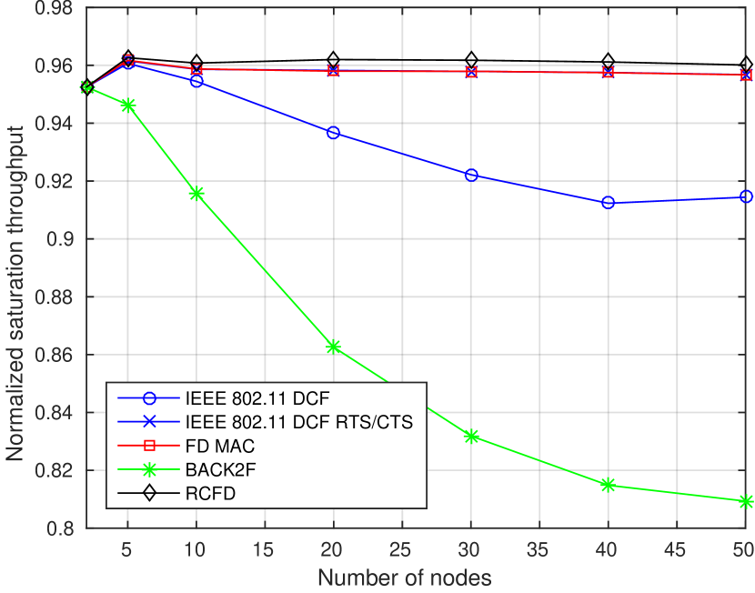
We have evaluated two different scenarios in our network simulations. In each scenario, the aforementioned performance metrics for the considered MAC algorithms have been evaluated for a different number of nodes in the network. The scenarios differ for the average duration of the data transmission, expressed as the ratio between the average payload size and the data transmission rate .
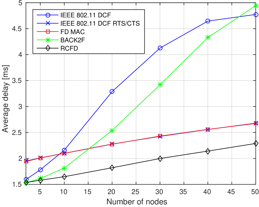
The results are reported in terms of normalized system throughput and average delay in Fig. 4 for the case of long average data transmission time, i.e., bits and Mbit/s, yielding an average data transmission time of 1 ms. It can be noticed that the RCFD algorithm provides the best performance in terms of both throughput and delay. As far as throughput is concerned, the performance of RCFD does not degrade when the number of nodes in the network increases. The same behavior can be observed for the two algorithms based on time–domain RTS/CTS (FD MAC and IEEE 802.11), which provide a normalized throughput almost equal to that of RCFD. Conversely, both standard IEEE 802.11 DCF and BACK2F decrease their performance as the network becomes denser, with the latter suffering nearly a 15 throughput degradation for a large network size. A similar situation can be observed when taking average delay into account. Indeed, RCFD yields the lowest delay, outperforming the two strategies based on time–domain RTS/CTS by roughly 33 as for all of them the delay increases linearly with the number of nodes. On the contrary, the average delay in IEEE 802.11 and BACK2F increases much more significantly with the network size, especially for the case of large network size, where the average delay is more than doubled with respect to RCFD.
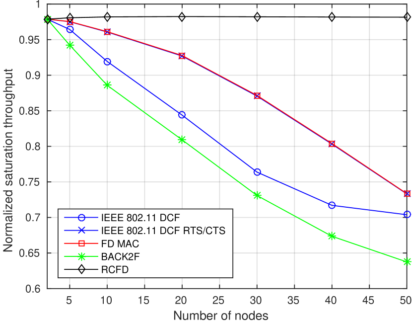
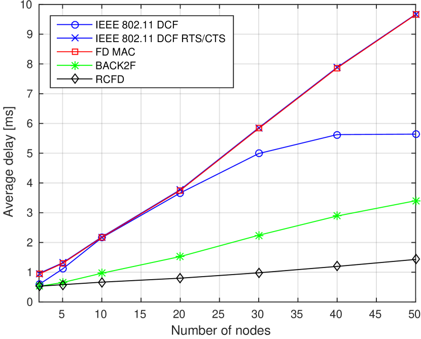
The outcomes for the other scenario are reported in Fig. 5, for an average payload length of bits and a raw data rate of Mbit/s, thus yielding a packet transmission time of 3.7 s. With respect to the previous scenario, in this case the strategies based on time–domain RTS/CTS (FD MAC and IEEE 802.11) perform significantly worse, since the impact of the overhead caused by additional frame exchanges is much more significant. Indeed, looking at the throughput in Fig. 5a, it can be observed that in these two strategies the performance significantly degrades when the network size increases, with a decrease of more than 20 for a large number of nodes. As far as the average delay is concerned, the performance degradation is even more evident, as the two time–domain strategies offer the worst performance among all the considered MAC algorithms. Conversely, our proposed RCFD algorithm is able to guarantee an almost constant normalized throughput (close to 1) regardless of the network size, and to ensure a very low average delay, always smaller than 2 ms. This is by far the best performance compared to all the other MAC layer algorithms considered.
V Conclusions
In this paper we proposed RCFD, a full–duplex MAC protocol based on a frequency–domain channel access procedure. We showed through simulation that this strategy provides excellent performance in terms of both throughput and delay, also in the case of dense networks with a large number of nodes, compared to other standard and state–of–the–art MAC layer schemes.
A natural, though challenging, extension of this work is the experimental validation of the proposed MAC layer protocol on devices capable of FD operations and able to transmit OFDM symbols using only some specific subcarriers. A theoretical analysis of the proposed scheme can also be envisioned, following the analytical approaches that have been used to study traditional MAC protocols for wireless networks. Finally, the impact of a non–ideal channel must be investigated, especially for the case of impairments that may occur during the channel contention phase.
References
- [1] J. I. Choi, M. Jain, K. Srinivasan, P. Levis, and S. Katti, “Achieving Single Channel, Full Duplex Wireless Communication,” in Proceedings of the 16th ACM Annual International Conference on Mobile Computing and Networking (MobiCom), September 2010, pp. 1–12.
- [2] M. Duarte and A. Sabharwal, “Full-duplex wireless communications using off-the-shelf radios: Feasibility and first results,” in Proceedings of the 44th Asilomar Conference on Signals, Systems and Computers (ASILOMAR), November 2010.
- [3] M. Duarte, A. Sabharwal, V. Aggarwal, R. Jana, K. Ramakrishnan, C. Rice, and N. Shankaranarayanan, “Design and Characterization of a Full-Duplex Multiantenna System for WiFi Networks,” IEEE Transactions on Vehicular Technology, vol. 63, no. 3, pp. 1160–1177, March 2014.
- [4] A. Sahai, G. Patel, and A. Sabharwal, “Pushing the limits of full-duplex: Design and real-time implementation,” Rice University Technical Report TREE1104, 2011.
- [5] J. Y. Kim, O. Mashayekhi, H. Qu, M. Kazandjieva, and P. Levis, “Janus: A novel MAC protocol for full duplex radio,” Stanford University, Computer Science Technical Reports (CSTR), July 2013.
- [6] S. Sen, R. R. Choudhury, and S. Nelakuditi, “Listen (on the frequency domain) before you talk,” in Proceedings of the 9th ACM SIGCOMM Workshop on Hot Topics in Networks, October 2010.
- [7] IEEE Standard for Information technology–Telecommunications and information exchange between systems–Local and metropolitan area networks–Specific requirements. Part 11: Wireless LAN Medium Access Control (MAC) and Physical Layer (PHY) Specifications, IEEE Std., March 2012.
- [8] B. Radunovic, D. Gunawardena, P. Key, A. Proutiere, N. Singh, V. Balan, and G. Dejean, “Rethinking Indoor Wireless Mesh Design: Low Power, Low Frequency, Full-duplex,” in Proceedings of the IEEE International Conference on Sensing, Communication and Networking (SECON), June 2010.
- [9] A. Sabharwal, P. Schniter, D. Guo, D. Bliss, S. Rangarajan, and R. Wichman, “In-Band Full-Duplex Wireless: Challenges and Opportunities,” IEEE Journal on Selected Areas in Communications, vol. 32, no. 9, pp. 1637–1652, September 2014.
- [10] D. Kim, H. Lee, and D. Hong, “A Survey of In-band Full-duplex Transmission: From the Perspective of PHY and MAC Layers,” IEEE Communications Surveys and Tutorials, vol. 17, no. 4, pp. 2017–2046, October 2015.
- [11] M. Jain, J. I. Choi, T. Kim, D. Bharadia, S. Seth, K. Srinivasan, P. Levis, S. Katti, and P. Sinha, “Practical, Real-time, Full Duplex Wireless,” in Proceedings of the 17th ACM Annual International Conference on Mobile Computing and Networking (MobiCom), September 2011.
- [12] N. Singh, D. Gunawardena, A. Proutiere, B. Radunović, H. V. Balan, and P. Key, “Efficient and fair MAC for wireless networks with self-interference cancellation,” in Proceedings of the IEEE International Symposium on Modeling and Optimization of Mobile, Ad Hoc, and Wireless Networks (WiOpt), May 2011, pp. 94–101.
- [13] W. Cheng, X. Zhang, and H. Zhang, “RTS/FCTS mechanism based full-duplex MAC protocol for wireless networks,” in Proceedings of the IEEE Global Communications Conference (GLOBECOM), December 2013, pp. 5017–5022.
- [14] K. Miura and M. Bandai, “Node architecture and MAC protocol for full duplex wireless and directional antennas,” Proceedings of the IEEE International Symposium on Personal, Indoor and Mobile Radio Communications (PIMRC), pp. 369–374, September 2012.
- [15] A. Sadeghi, S. Mosavat-Jahromi, F. Lahouti, and M. Zorzi, “Multi-hop wireless transmission with half duplex and imperfect full duplex relays,” in Proceedings of the 7th IEEE International Symposium on Telecommunications (IST), September 2014, pp. 1026–1029.
- [16] K. Tamaki, A. Raptino H., Y. Sugiyama, M. Bandai, S. Saruwatari, and T. Watanabe, “Full Duplex Media Access Control for Wireless Multi-Hop Networks,” Proceedings of the 77th IEEE Vehicular Technology Conference (VTC), June 2013.
- [17] J. Zhang and Q. Zhang, “Use your frequency wisely: Explore frequency domain for channel contention and ACK,” in Proceedings of the IEEE International Conference on Computer Communications (INFOCOM), March 2012, pp. 549–557.
- [18] D. Bharadia, E. McMilin, and S. Katti, “Full Duplex Radios,” in Proceedings of the ACM Special Interest Group on Data Communication Conference (SIGCOMM), August 2013, pp. 375–386.
- [19] S. Sen, R. Roy Choudhury, and S. Nelakuditi, “No time to countdown: migrating backoff to the frequency domain,” in Proceedings of the 17th ACM Annual International Conference on Mobile Computing and Networking (MobiCom), September 2011, pp. 241–252.
- [20] M. Luvisotto, A. Sadeghi, F. Lahouti, S. Vitturi, and M. Zorzi, “RCFD: A Novel Channel Access Scheme for Full-Duplex Wireless Networks Based on Frequency Domain Contention,” Arxiv, Feb. 2016. [Online]. Available: http://arxiv.org/
- [21] P. Gupta and P. Kumar, “The capacity of wireless networks,” IEEE Transactions on Information Theory, vol. 46, no. 2, pp. 388–404, Mar 2000.