Multi-scale Full-orbit Analysis on Phase-space Behavior of Runaway Electrons in Tokamak Fields with Synchrotron Radiation
Abstract
In this paper, the secular full-orbit simulations of runaway electrons with synchrotron radiation in tokamak fields are carried out using a relativistic volume-preserving algorithm. Detailed phase-space behaviors of runaway electrons are investigated in different dynamical timescales spanning 11 orders. In the small timescale, i.e., the characteristic timescale imposed by Lorentz force, the severely deformed helical trajectory of energetic runaway electron is witnessed. A qualitative analysis of the neoclassical scattering, a kind of collisionless pitch-angle scattering phenomena, is provided when considering the coupling between the rotation of momentum vector and the background magnetic field. In large timescale up to one second, it is found that the initial condition of runaway electrons in phase space globally influences the pitch-angle scattering, the momentum evolution, and the loss-gain ratio of runaway energy evidently. However, the initial value has little impact on the synchrotron energy limit. It is also discovered that the parameters of tokamak device, such as the toroidal magnetic field, the loop voltage, the safety factor profile, and the major radius, can modify the synchrotron energy limit as well as the strength of neoclassical scattering. The maximum runaway energy is also proved to be lower than the synchrotron limit when the magnetic field ripple is considered.
I Introduction
As a typical multi-scale process, the dynamics of runaway electrons in tokamak has emerged as an important topic in the study of magnetic confined fusion devices. During tokamak experiments, many operation phases, such as fast shutdown, disruptions, and strong current drive, are accompanied by the generation of runaway electrons Yoshino et al. (1997); Jaspers et al. (1996); Helander et al. (2000, 2002); Fülöp et al. (2009); Gill et al. (2000); Jaspers et al. (1993); Nygren et al. (1997); Parks et al. (1999); Rosenbluth and Putvinski (1997); Yoshino and Tokuda (2000); Tamai et al. (2002); Lehnen et al. (2008); Finken et al. (2007); Fisch (1987). The collisional friction from the background plasma cannot prevent the acceleration of these energetic electrons if the inductive loop electric field is larger than a critical value Dreicer (1959); Connor and Hastie (1975). Through the acceleration by the electric field, the velocity of runaway electrons can be sped up to nearly the light speed. Runaway electrons carrying energies from 10 to 100 MeVs have been observed in different experiments Bartels (1994); Kawamura et al. (1989); Bolt et al. (1987); Jaspers et al. (2001). Once hitting the plasma-facing components (PFCs), these energetic electrons can damage the tokamak devices badly. Because of the strong relativistic effect, the synchrotron radiation becomes an important ingredient of runaway electron physics. For extremely energetic runaway electrons, their synchrotron radiation loss could be strong enough to balance out the acceleration by the loop electric field. The radiation dissipation then provides runaway electrons an upper bound of energy, i.e., the synchrotron energy limit Martín-Solís et al. (1998, 1999); Liu et al. (2014); Guan et al. (2010). The typical duration for a runaway electron with low energy (1keV-1MeV) to reach the energy limit has the order of magnitude of one second while the smallest timescale of Lorentz force is Liu et al. (2014, 2016), which means the dynamical behavior of runaway electrons spans about 11 orders of magnitude in timescale. The multi-scale character poses great difficulty to a satisfying physical treatment of runway dynamics.
Through averaging out the gyro-motion, the gyro-center theory can reduce the span of timescales by about three orders and is used widely in dealing with runaway electron dynamics. Fruitful results of this theory have been accomplished. Considering the gyro-center approximation regardless of the toroidal geometry, one can transfer the full-orbit dynamical equations of runaway electrons to a set of relaxation equations which are much easier to solve theoretically and numerically Liu et al. (2014). By use of relaxation equations, the momentum evolution structure as well as energy limit has been studied in detail under several kinds of dissipations, such as collision, synchrotron radiation, and bremsstrahlung radiation Martín-Solís et al. (1998, 1999); Bakhtiari et al. (2005). Meanwhile, the restriction effect of magnetic ripple on the maximum energy has also been discussed in this way Martín-Solís et al. (1999). If involving the toroidal geometry, some extra geometry-related phenomena arise, often dubbed neoclassical effects. The Ware-pinch effect shows an inward drift of trapped orbit Ware (1970); Guan et al. (2010); Fisch and Karney (1981), while the neoclassical drift provides an outward radial drift velocity of transit runaway orbits Qin et al. (2011). Both of these phenomena reflect the conservation of the toroidal canonical angular momentum. Recently, gyro-center simulations have been equipped with structure-preserving discrete methods and shown better long-term numerical accuracy than traditional methods Guan et al. (2010); Liu et al. (2014); Zhang et al. (2014).
Unlike gyro-center theory, the full-orbit analysis can keep entire physical information covering all timescales of runaway dynamics. Especially, a recent full-orbit simulation on runaway electrons has shown that the assumption of gyro-center theory no longer holds in tokamak magnetic field if the runaway electrons are accelerated to several tens of MeVs Liu et al. (2016). Because of the high energy, the change of background magnetic field direction encountered by runaway electrons is significant even within one gyro-period. The violent change of magnetic field causes a full-orbit effect, the collisionless neoclassical pitch-angle scattering, which arises from the toroidal geometry and causes a violent momentum exchange between parallel and perpendicular directions. It also leads to a drift in momentum space and the significant run-up of perpendicular momentum, which provides a new picture of runaway momentum structure. The energy limit is also found to be higher when the full-orbit effect is considered. Therefore, the full-orbit dynamical analysis is vital to obtain reasonable descriptions on runways.
In this paper, we discuss the detailed full-orbit runaway dynamics in views of both small (-) and large (-) timescales and analyze the influences of tokamak design parameters on the long-term motion of runaway electrons. A throughout simulation of the multi-timescale behavior of runways requires more than time steps, which is an astronomically big number and cannot be properly implemented by traditional numerical methods. To tackle the global accumulation of coherent errors for such long-term simulation, we follow the method in Ref. Liu et al. (2016) and use a relativistic volume-preserving algorithm (VPA) Zhang et al. (2015). As a geometric algorithm, the relativistic VPA possesses long-term numerical accuracy and stability Guan et al. (2010); He et al. (2015a); Xiao et al. (2013); Liu et al. (2014); Qin et al. (2013); Qin and Guan (2008); Zhang et al. (2014, 2015); He et al. (2015b, 2016); Qin et al. (2015); Xiao et al. (2015a, b). The secular full-orbit dynamics of runaway electrons is obtained through directly solving the Lorentz force equations. The synchrotron radiation is included in the physical model, when the collisional force is ignored.
The characteristic timescale imposed by magnetic force reflects the smallest timescale of runaway dynamics, which can be defined as the gyro-period
| (1) |
where is the Lorentz factor, is the rest mass of electron, is the unit charge, and denotes the strength of magnetic field. Although gyro-center theory breaks down for energetic runaways in toroidal geometry, the gyro-period can still be used as an available characteristic parameter for the small timescale. This is because that the failure of the gyrocenter condition is mainly due to the rapid change of the direction of the magnetic field, while doesn’t vary a lot during each gyro-period. The practicability of can also be analyzed in the view of the rotation operator. We will show that in the gyro-period timescale the trajectory of an energetic runaway electron is elongated both toroidally and poloidally, and the corresponding will increase to about one twentieth of the transit period. As a result, the local magnetic field witnessed by an energetic runaway electron rotates rapidly, and the norm of magnetic rotation axial vector, namely, , becomes comparable with , which leads to the collisionless neoclassical pitch-angle scattering. A qualitative description of the collisionless scattering is given through the coupling between the rotations of momentum and magnetic vector. The momentum drift caused by the long-term accumulation of collisionless scattering effect is analyzed. To be specific, the perpendicular momentum of a runaway electron increases in the direction of which is approximately in the direction of z-axis.
The long-term evolution of momentum and energy are investigated for runaways with different initial conditions in phase space. Four main characteristics of the momentum evolution structure are discussed: (a) the zero-point position of perpendicular momentum, (b) the oscillation amplitude when reaching energy limit, (c) maximum parallel momentum, and (d) maximum perpendicular momentum. Among these four characteristics, (a) and (b) correspond to the fine oscillating structures of runaway orbit, meanwhile (c) and (d) are related closely to the synchrotron energy limit Liu et al. (2016). It will be shown that the zero-point of perpendicular momentum and the amplitude of oscillation are impacted significantly by the initial pitch-angles. Larger initial perpendicular momentum will cause larger zero-point position and stronger oscillation in small timescale. However, the initial momentum samplings have little influence on the energy limit. The impact of the initial configuration position on the long-term momentum evolution is also negligible. For a deeper insight, we define two quantities to describe the long-term integral behavior of runaway energies, i.e., the energy loss-gain ratio and the energy balance time. The energy loss-gain ratio is defined as the ratio of the total energy loss through radiation to the energy gained from the loop electric field. This ratio is influenced by the initial runaway momentum significantly but is nearly independent of the initial position. The evolutions of energy loss-gain ratio under different initial phase space samplings have similar behaviors in the vicinity of the energy limit. The energy balance time describes the time required for a new-born runaway electron to run up to its energy limit, which is approximately independent of its initial values in the phase space.
Finally, in order to describe tokamak experimental research on runaways, the influences of tokamak parameters, including the loop electric field, the background magnetic field, the major radius, and the safety factor , on both the energy limit and the strength of neoclassical pitch-angle scattering are analyzed. Large loop inductive electric field can impel runaways with high energy in short time. On the other hand, the strength of magnetic field mainly contributes to the neoclassical effects. Smaller magnetic field will stall for the energy balance time but bump up the perpendicular momentum more significantly. As a key parameter of tokamaks, the major radius affects the energy limit and the balance time through changing the power of radiation. Smaller major radius results in stronger radiation and shorter balance time. The strength of neoclassical scattering decreases slightly as the growth of major radius. The influence of safety factor is also discussed. Involving several different effects, the maximum energy, the balance time, and the maximum perpendicular momentum roughly depend on the safety factor linearly. When is small, the dependence of momentum oscillation on is more sensitive. When is larger than 2, the amplitude of oscillation approaches to a constant approximately. Lastly, we also study the effect of magnetic field ripple due to the finite number of toroidal coils. The energy limit is proved to be lower than the synchrotron limit when magnetic ripple exists, which is consistent with the theoretical analysis in Ref. Laurent and Rax (1990).
This article is organized as follows. Section II gives an introduction of the physical model and the algorithm used in the numerical research. In Sec. III, the full-orbit behavior of a runaway electron is analyzed in the timescale of . The long-term evolution behaviors of momentum and energy are studied under different initial phase space samplings in Sec. IV and Sec. V respectively. Section VI focuses on how the parameters of tokamak affect the energy limit and the neoclassical pitch-angle scattering of runaway electrons. And Sec. VII concludes this paper and our future plans.
II Physical Model and numerical method
The first-principle physical model of runaway electron is the solution of relativistic Lorentz force equations. The synchrotron radiation is included as the dominate channel of runaway energy dissipation. The collisional resistance is neglected because its effect is small enough compared with the collisionless pitch-angle scattering Liu et al. (2016). Consequently, we describe the runaway electrons by use of the following equations,
| (2) |
| (3) |
| (4) |
where , , are respectively position, momentum, and velocity of a runaway electron, and denote electric and magnetic field. The radiation force is defined as Liu et al. (2016)
| (5) |
where is the radiation power determined by Jackson (1962)
| (6) |
Here, denotes the permittivity in vacuum, is the speed of light in vacuum, and is the acceleration vector.
The full-orbit simulation of Eqs. 2-6 is essentially a multi-scale numerical problem. To achieve the omni-timescale dynamics of runaway electron, the minimum time resolution should be less than , which is typically around . However, since the timescale of acceleration process of runaway electrons is one second, hundreds of billions of steps are needed in numerical calculation. Traditional algorithms, such as the fourth-order Runge-Kutta method, can only restrict one-step numerical error. So the global coherent accumulation of numerical errors from such a large number of simulation steps will go far beyond the tolerance of numerical accuracy. To solve the numerical error problem for long-term simulations, we deal with the problem by use of a relativistic volume-preserving algorithm Zhang et al. (2015). The long-term numerical stability and accuracy of the relativistic VPA has been verified. According to the construction of relativistic VPA, the motion equations of runaway electrons are discretized as
| (7) |
| (8) |
| (9) |
| (10) |
| (11) |
| (12) |
| (13) |
where the subscript, , denotes the -th step, is the time interval, is defined as
| (14) |
and the symbol denotes the Cayley transform Zhang et al. (2015). The radiation force is treated as an effective electric field in the discrete equations. In this paper, a typical configuration for tokamak field is used, i.e.,
| (15) |
| (16) |
Here we use the cylindrical coordinate system . In Eqs. 15 and 16, and are respectively the toroidal and poloidal unit vectors, is the major radius, denotes safety factor, is the strength of loop electric field, and is the magnitude of background magnetic field. The time step of simulation is set as , which is about 1% of .
III Runaway dynamics in -timescale
In this section, we offer a straightforward full-orbit picture of runaway electron dynamics in -timescale. Because it has been proved that the gyro-center model breaks down for the dynamics of energetic runaway electrons Liu et al. (2016), the motion of runaways in -timescale looks quite different from the gyro-center picture. Here we set calculation parameters based on a typical tokamak, that is , , , , and . The initial position is chosen as , , and the initial parallel and perpendicular momentums are set as and respectively.
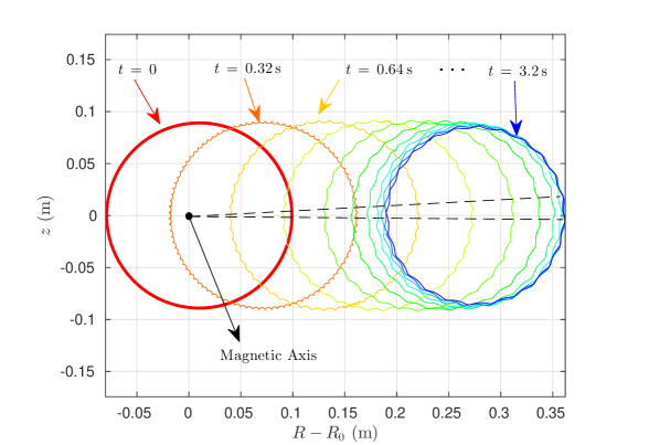
Figure 1 depicts snapshots of poloidal projection of runaway orbits at different moments. Besides the outward neoclassical drift orbit similar to the results from the gyrocenter code Guan et al. (2010); Qin et al. (2011), it can also be observed that there exist ripple structures superimposed on each circle orbit. These fine ripple structures, which cannot be recovered by gyro-center models, correspond to the runaway motion in -timescale and become more obvious as time going. Accompanying the increase of runaway energy, both the velocity and of runaway electrons grows. The runaway orbit during each is elongated both toroidally and poloidally. As shown in Fig. 1, the ripple structure becomes more and more evident due to the enhance of the orbit elongation. Because one circular orbit projected in the poloidal plane actually corresponds to a transit period , the decrease of the ripple structure number with energy increase implies the decrease of and hence the increase of . For example, at , there are only about 24 ripples during one poloidal period, which means there are 24 s in one transit period.
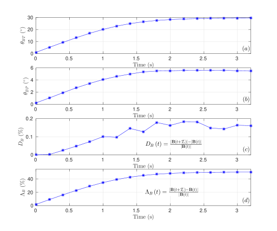
The change of magnetic field witnessed by the runaway electron within one gyro-period has a close relation to the deformation of runaway orbit. The variance of the background magnetic field during at different time is plotted in Fig. 2, indicated by the toroidal rotation angle of magnetic field , the poloidal rotation angle of magnetic field , the change rate of magnetic strength , and the relative increment of magnetic vector . The definition reflects relative change of magnetic strength within one gyro-period. The relative increment of magnetic vector during one gyro-period is defined as , which includes the change of direction of the magnetic field. According to Fig. 2c, during each gyro-period the increment of the magnetic strength , which reflects the small radial size of the ripple structure, is rather small compared with . The poloidal and toroidal rotation angles of magnetic field, and , can be approximately expressed by the poloidal and toroidal angles spanned by a single ripple structure. The dashed lines in Fig. 1 shows that the maximum poloidal angle spanned by a ripple is about , which is consistent with the result in Fig. 2b. Compared with , is significantly larger, see Fig. 2a. The runaway electron runs about in the toroidal direction and in the poloidal direction within one transit period if . Then at , 24 ripples appearing in one transit period means that each ripple structure covers about in the toroidal direction, which is consistent with the maximum in Fig. 2a. Therefore, we can conclude that the violent change of magnetic field in timescale is dominated by its toroidal rotation.
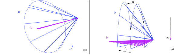
When analyzing the dynamics in the momentum space, one can treat the effect of magnetic field as a rotation operation due to the formation of Lorentz force He et al. (2015a). The unit magnetic vector determines the axis of instantaneous momentum rotation, while the magnetic strength reflects the velocity of rotation as well as the value of . If is approximately a constant in , the track of spans a symmetric cone around , see Fig. 3a. However, if the characteristic variation time of is comparable with , the rotations of and are coupled, see Fig. 3b, where , satisfying , denotes the rotation axial vector of . Therefore, the runaway’s pitch-angle undergoes significant change even in the timescale of . In Fig. 3b, and are marked using black arrows, where the dot on physical quantities denotes total derivative with respect to time. For runaway electrons carrying negative electric charge, always rotates counterclockwise with respect to . The purple trails of in Fig. 3b establish the rotation plane of . It is readily to see that the value of is positive above the plane and negative under the plane. The coupling between the rotations of and results in asymmetric distribution of perpendicular momentum on two sides of magnetic rotation plane, namely, the average of perpendicular momentum is larger when . Equivalently, the rotating momentum can be regarded as being tilting towards the direction of , i.e., the average always increases, where is the direction of rotation axial vector, and the bracket denotes the averaging operation over . On the contrary, a runaway positron carrying positive electric charge always rotates around clockwise. Consequently, the runaway positron’s momentum tilts towards the direction of , namely increases. In the case of our simulation, the toroidal component of magnetic field directs to . Therefore, if neglecting the poloidal component of , which is relative small, we have approximately. Then the average value of -component of perpendicular momentum keeps growing. This effect is enhanced when the rotation of becomes more rapid within one gyro-period. This theoretical analysis agrees with the numerical results in Ref. Liu et al. (2016) and offers a direct description of the origin of collisionless pitch-angle scattering.
IV Secular Evolution of runaway Momentum
Due to the collisionless neoclassical scattering, the temporal evolution of runaway momentum shows strong oscillation in small timescale and bumps up in large timescale. The structure of momentum evolution exhibits complex multi-scale characteristics, which is different from the results of gyro-center model. In this section, we aim to find the dependence of the long-term momentum structure on the initial conditions of runaway electrons in the phase space. The setup of tokamak parameters are the same as those in Sec. III.
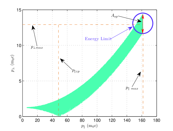
A typical momentum evolution structure is plotted in the momentum space, where the abscissa is the parallel momentum and the ordinate is the perpendicular momentum , see Fig. 4. The runaway electron starts from and . In the beginning , the oscillation amplitude increases significantly. Then the perpendicular momentum touches at a zero-point due to the oscillation broadening. After passing the zero-point, the global evolution of the momentum curve inclines to the ordinate, which means the rapid increase of the perpendicular momentum. Finally, once the loop electric field is balanced out by the radiation, the momentum band ceases near , with obvious oscillation in and negligible oscillation in . The marked by the purple circle in Fig. 4 corresponds to the synchrotron energy limit. According to Fig. 4, the complete momentum-space structure of runaway evolution can be basically established by four principal parameters, that is the zero-point value of parallel momentum , the oscillation amplitude of perpendicular momentum near the energy limit , the maximum parallel momentum , and the average maximum perpendicular momentum . Among them, and reflects the nature of momentum oscillation and collisionless pitch-angle scattering, and and provide the information of the energy limit Liu et al. (2016).
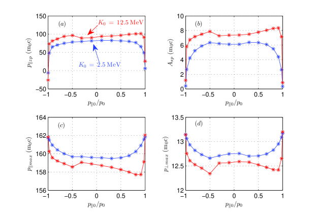
Different initial conditions of runaway electrons in the momentum space mainly alter the position of zero-point and the amplitude of oscillation, i.e., the properties of the neoclassical scattering, but have little impact on the maximum momentum and energy limit. In Fig. 5, we calculate the dependencies of key momentum structure parameters, i.e., (a) , (b) , (c) , and (d) , on initial conditions in the momentum space, under different initial kinetic energies and initial pitch-angles. The two sampling initial kinetic energy values are chosen as and . The initial pitch-angles are uniformly sampled from to in the range . The negative value of means that the runaway electron initially travels opposite to the electric acceleration direction, i.e., the backward runaways Fisch (1987); Karney and Fisch (1986). The effect of initial gyro-phase is not counted in considering the gyro-symmetry in the low energy range. According to Fig. 5a, the value of parallel momentum at zero-point is sensitive to the initial pitch-angle. It is readily to see that the value of parallel momentum at zero-point tends to its initial value, i.e., , in the small pitch-angle limit . With the increase of , or the decrease of , the value of parallel momentum at zero-point moves toward the positive direction of . On the other hand, higher results in larger . The oscillation amplitude of the momentum structure is also closely related to initial momentum, see Fig. 5b. The amplitude grows with the decrease of absolute value of and the increase of initial energy. Especially, if the initial pitch-angle is large enough, the oscillation amplitude may catch up to one half of the maximum perpendicular momentum, see Fig. 5b and Fig. 5d. Conversely, as shown in Fig. 5c and Fig. 5d, the initial momentum has relatively little effect on and . The relative variations resulted from different or are only about 5% or less.
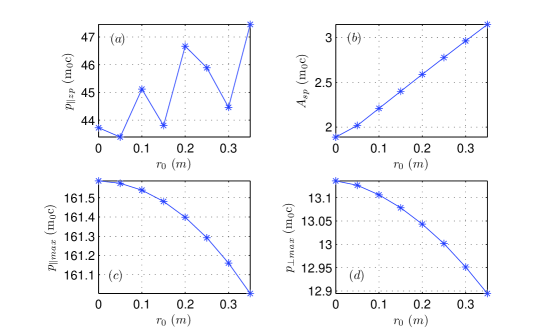
The influence of initial positions in the configuration space on the momentum evolution is negligible, as shown in Fig. 6. Since the initial position samplings possess approximate symmetry in both toroidal and poloidal directions, the initial positions of runaway electrons are sampled densely on radial positions. Here denotes the radial component of toroidal coordinates. The relative variation of is less than 6% for different initial radial positions in the range . For larger , both the electric field and the magnetic field witnessed by a runaway electron are smaller when the transit orbit drifts away from the magnetic axis. So less energy is delivered to runaway electrons from electric field with the increase of . We can see from Figs. 6c and 6d that and decrease slightly when gets larger, but their relative variations are small. At the same time, because smaller magnetic field implies stronger collisionless scattering Liu et al. (2016), the oscillation amplitude of momentum is proportional to , which is reflected in the plot of in Fig. 6b.
V Integral Attributes of Energy Evolution
In this section, we focus on two important attributes of energy evolution, namely, the energy loss-gain ratio and the energy balance time. The energy loss-gain ratio of runaway electrons is defined as the ratio of the energy dissipation through radiation to the energy gained from the loop electric field. The energy balance time describes the time required by a low-energy runaway electron from its birth to reaching the energy limit. Unlike the energy limit, which can be analyzed through the stable point of a dynamical system, the energy loss-gain ratio and the energy balance time involves integral quantities over full orbits. Since it is too difficult to analytically calculate the integrations for multi-timescale dynamics of runaway electrons in tokamak fields, long-term numerical integration turns out to be the only practical way to achieve the accurate loss-gain ratio and energy balance time. The parameters of tokamak we use in this section are the same as those in Sec. III.
V.1 Energy loss-gain ratio
The energy loss-gain ratio is defined as
| (17) |
where is the energy loss from the synchrotron radiation, and is the net runaway energy gained from electric field. After a runaway electron reaches its energy limit, becomes a constant which is expressed using the symbol . Therefore, the energy loss-gain ratio has a simple form at energy limit, namely,
| (18) |
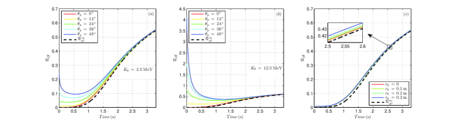
In Fig. 7, the evolution of is plotted with different initial pitch-angles, kinetic energy, and radial positions. From Fig. 7a and Fig. 7b, we can see that the initial pitch-angle and energy mainly influence at the early stage of acceleration. Larger pitch-angle means smaller parallel velocity, which hence results in weaker electric acceleration power and stronger radiation through perpendicular motion. The increase of initial energy will enhance the radiation. Therefore, grows together with the increase of and . On the other hand, according to Fig. 7c, the impact of initial radial position on the behavior of is very weak. All the curves in Fig. 7 asymptotically approach to the reference line of after . Therefore the initial position and momentum of runaways has little effect on the energy loss-gain ratio after reaching the energy limit, when about 55% of the electric energy has been radiated.
V.2 Energy balance time
We now focus on how long it takes for a runaway electron to reach its energy limit, i.e., the energy balance time . To calculate , the start point and end point of acceleration process should be determined. The end point is defined as the moment when the loop electric field is balanced by the synchrotron radiation. At this time, because of the neoclassical pitch-angle scattering, physical quantities, such as momentum, electric acceleration power, and radiation power, show strong oscillations in the gyro-period timescale. The electric field is balanced out by the radiation loss only in the sense of long-term average. Therefore, we define the average loss-gain power ratio as
| (19) |
where is the radiation power, is the electric acceleration power and the bracket means the average over a transit period. Then it is convenient to define the end point of as the moment when . The end point of can also be inferred from the relative behavior of and . Because the evolutionary trend of becomes the same as that of after reaching energy limit, the moment when the curves of and begin to overlap also indicates the finish of acceleration.
The settlement of the start point of , however, is more complex since runaway electrons are born with different phase-space states and origins. There is even not a clear criterion for the emergence of a single runaway electron because of its statistical essence. Fortunately, it can be verified that different initial energies matters little to the energy balance time for runaways under several MeVs. The typical electric field can accelerate a low-energy runaway electron to several MeVs within 10% Liu et al. (2016). In this paper, we set the start-up energy of a runaway electron as . The arbitrariness of the setup of the start-up energy has small impact on the value of within the range of several MeVs. According to Fig. 7, it can also be observed that different initial samplings in phase space has little effect on .
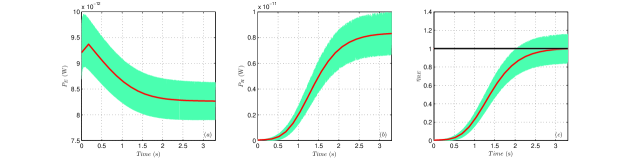
The typical evolutions of , , and are plotted in Fig. 8. All of these curves show strong oscillations. The transit-period average values are plotted using the red curves. The power of electric acceleration increases at the beginning because of the growth of runaway velocity. Once the runaway speed is close enough to , the electric acceleration power is dominated by the strength of the loop electric field. Since the electric field is inversely proportional to radial position, decreases accompanied by the outward drift of runway transit orbits, see Fig. 8a. The radiation power monotonously increases with the runaway energy accompanied by stronger oscillations, see Fig. 8b. The red curve in Fig. 8c is a typical evolution of , which reflects that the loss-gain rate power ratio climbs steeply in the midterm of runaway acceleration. The energy balance time is around in this case.
VI Influences of tokamak Device Parameters
Many experiments have confirmed the existence of runaway electrons with energies ranging from - in tokamak devicesGill (1993); Jarvis et al. (1988); Wongrach et al. (2014). To describe and further understand the experimental results, it is necessary to study the dependence of runaway dynamical properties on the device parameters. In this section several characteristics of runaways, which may be experimentally diagnosed directly or indirectly, such as the maximum energy , the energy balance time , the oscillation amplitude of perpendicular momentum near the energy limit , and the average maximum perpendicular momentum , are discussed. The influences from three key tokamak device parameters are considered, including the strength of tokamak field, the major radius, and the safety factor. The impact of magnetic field ripple is also studied through full-orbit simulations.
As vital design parameters, the intensities of equilibrium tokamak fields are reflected in and . The toroidal curvature of fields is determined by the major radius , while the poloidal curvature is reflected in the safety factor . All these parameters influence the energy limit and collisionless pitch-angle scattering by stepping in different aspects of runaway dynamics, such as the acceleration, the synchrotron radiation, and the change rate of magnetic field during each gyro-period. Larger leads to stronger acceleration, while increasing results in the mitigation of collisionless pitch-angle scattering. The increase of magnetic curvature corresponds to the enhancement of radiation and toroidal effect. Considering the loop electric field and toroidal magnetic decreases radially, the neoclassical drift velocity, approximately given by Guan et al. (2010); Qin et al. (2011), also interferes the energy limit rule and the neoclassical scattering process. The change of one single device parameter thus may affect the runaway dynamics in several interactional mechanisms. On the other hand, the magnetic field ripple can also impose stochastic instability to runaway dynamics through the nonlinear resonance, which restricts the maximum runaway energy below the synchrotron limit Laurent and Rax (1990). In this section, the initial conditions are sampled in the phase space the same as in Sec. III.
VI.1 Influences of field strength
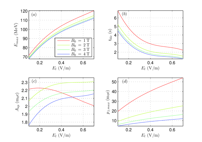
Figure 9 summarizes the influences from and on , , , and . Curves with different colors correspond to different central magnetic field strength. The major radius is set as and the safety factor is . In tokamak experiments, the loop electric field has the strongest impact on the runaway energy limit. During disruptions the energy of plasma is released through a strong inductive loop electric field. According to Figs. 9a and 9b, the runaways can reach higher energy limits in shorter time when the loop electric field increases, thus posing more severe threat in major disruption.
On the other hand, the energy limit also depends on the magnetic field significantly. From Fig. 9a, we can see that the energy limit is higher for smaller . It can be noticed that the increment of due to the drop of is smaller than the result in Ref. Liu et al. (2016) which assumes a uniformly distributed electric field in the radial direction. The difference is caused by the neoclassical drift and radial distribution of electric field. For smaller , as the neoclassical drift is faster, the electric field witnessed by runaway electrons decreases faster. Therefore, the energy limit is reduced by several MeVs compared with that in the uniform electric field distribution. This mechanism also results in longer balance time, see Fig. 9b.
The strength of tokamak fields has small effects on the oscillation amplitude in small timescale, see Fig. 9c. The largest relative change of oscillation amplitude caused by tokamak field is about 10%. However, according to Fig. 9d, the ramp-up of perpendicular momentum in large timescale can be altered significantly by adjusting the strength of tokamak field. The growth rate of versus loop electric field becomes much larger for smaller magnetic field. This embodies stronger accumulation of neoclassical pitch-angle scattering on perpendicular runaway momentum, also more violent deviation from gyro-center model, for smaller magnetic field and large electric field.
VI.2 Influences of Major Radius
Next-generation tokamak devices possess larger major radius to achieve higher operation parameters. For example, the major radius of ITER is designed to be . Larger tokamaks have better confinement on fusion plasma as well as runaway electrons. More energy may release through runaway currents during major disruptions. It is obvious that runaway electron can gain more energy from the stronger electric field. On the other hand, we will show that, even with the same strength of electric field, the change of major radius will influence the energy limit rule and the neoclassical pitch-angle scattering directly. In this part, the tokamak field is set as and , and the safety factor is 2.
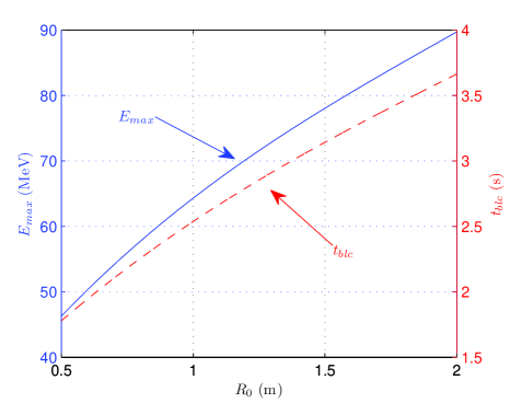
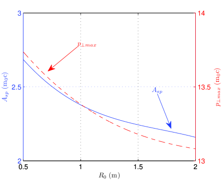
Figure 10 plots the energy limit and the balance time against different major radius. We can see that both the maximum energy and balance time increase proportional to the major radius approximately, because the synchrotron radiation closely depends on the curvature of the runaway orbit Martín-Solís et al. (1998). Smaller brings larger toroidal curvature and thus stronger radiation power. The runaway electrons have stronger synchrotron dissipation in small devices. As a result, their energy limit is lower and energy balance time is shorter.
The curvature of tokamak field reflects the significance of toroidal geometry. So the major radius also affects the collisionless pitch-angle scattering evidently. For devices with smaller major radius and larger toroidal curvature, the same distance traveled in toroidal direction brings more variation of the magnetic field direction. Consequently, the assumption of gyro-center model breaks down easier in smaller devices. As expected, the magnitude of oscillation at energy limit and the maximum perpendicular momentum drop with the increase of , see Fig. 11.
VI.3 Influences of safety factor
The safety factor is another important parameter of tokamaks, which reflects the geometric character of magnetic surface. Smaller corresponds to stronger poloidal magnetic field and more poloidal periods the magnetic line winding during each toroidal cycle. The curvature of magnetic line is determined toroidally by the major radius and poloidally by . Therefore, dynamical processes related to geometry configurations, such as synchrotron radiation and the neoclassical pitch-angle scattering, will be influenced by . Larger poloidal field also brings more difficult for electric field to accelerate the runaway electrons toroidally. Meanwhile, the value of also influence the neoclassical drift and thus the change of the local strength of electric field. Generally speaking, the safety factor has compound impacts on runaway dynamics, which makes its consequences vague by analyzing any individual factor. During disruptions, large portion of the poloidal magnetic field is induced by the runaway current. So the profile in major disruption involves self-consistent evolution of runway electrons. In this part, we use the parameters , , and , while the value of is sampled from 0.2 to 10.
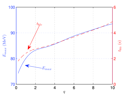
Figure 12 plots the energy limit and the energy balance time against the safety factor . Both and increases as becomes larger. This phenomenon comes from two main reasons. Firstly, for smaller , the poloidal field is stronger. Therefore, the toroidal acceleration of electric field is hindered. Secondly, when the toroidal curvature determined by the major radius keeps unchanged, smaller corresponds to larger poloidal curvature and thus stronger synchrotron radiation. Even though the neoclassical drift velocity is proportional to and the electric field decreases faster for larger due to its radial distribution, the numerical results in Fig. 12 imply that the effect of safety factor by modifying the neoclassical drift is weaker than the above two effects.
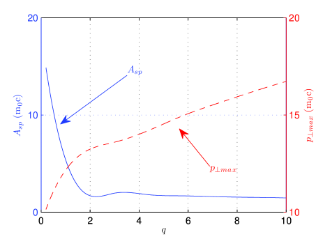
The influences of on collisionless pitch-angle scattering and maximum perpendicular momentum are plotted in Fig. 13. When the safety factor is less than 2, the amplitude of perpendicular momentum oscillation drops evidently with the increase of . Under this condition, the neoclassical scattering is extremely strong, and it is much easier for an energetic runaway electron to move cross magnetic surfaces. The rotation of magnetic field witnessed by runaway electrons becomes fast at the same time. The oscillation amplitude even exceeds the maximum perpendicular momentum at energy limit when is small enough. When is larger than 2, the geometric effects mainly come from the toroidal field. The dependence of on is not notable. On the other hand, the plot of shows the similar trend to that of , which increases monotonously with .
VI.4 Influence of magnetic field ripples on energy limit
In tokamaks, the toroidal magnetic fields are induced by toroidal coils with finite coil number, which leads to magnetic field ripples in experiments. According to L. Laurent and J. M. Rax’s paper in 1990, the stochastic instability caused by the nonlinear cyclotron resonances with magnetic field ripples can transfer the parallel energy to perpendicular direction and thus restrict runaway energy limit far below the synchrotron energy limit Laurent and Rax (1990). In this subsection, utilizing full-orbit simulations, we study the impacts of magnetic field ripples on the runaway energy limit. Besides the equilibrium electromagnetic field given by Eqs. 15 and 16, there also exist the radial perturbation of magnetic ripple , expressed by
| (20) |
| (21) |
where, , , and are three components of the toroidal coordinates, is the number of toroidal field coils, and and denote respectively the toroidal and poloidal harmonics. Following the discussion in Ref. Laurent and Rax (1990), we consider only the terms with in Eq. 21. The amplitude of perturbation magnetic field is given by the analytical approximation for small , namely,
| (22) |
where, is the radius of toroidal coils. Based on the Tore Supra tokamak Laurent and Rax (1990), we set the simulation parameters as , , , , , , and . The initial condition of the runaway electron is given by , , , and .
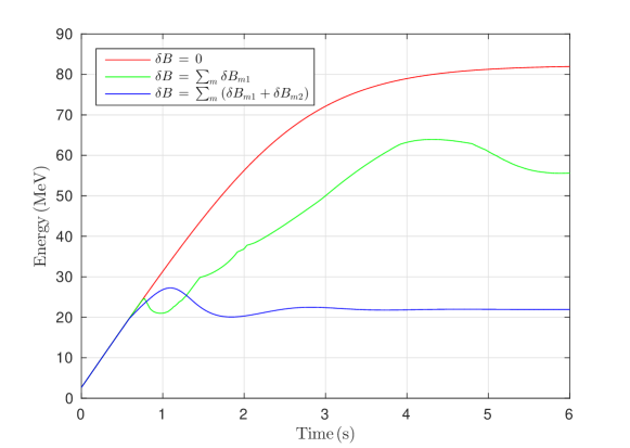
Figure 14 depicts the energy evolution of a runaway electron affected by different harmonics of magnetic ripple. Indicated by the red curve in Fig. 14, without the magnetic field ripple, the synchrotron energy limit is about . When considering the components of ripple field, and , the maximum runaway energy decreases to about approximately, see the green curve in Fig. 14. The restriction of the components of ripple field on runaway energy is more significant. As shown by the blue curve, if we add the components of , namely, and , the energy limit is reduced to . The results in Fig. 14 exhibit that the magnetic ripples can limit the maximum runaway energy far below the synchrotron limit, which is consistent with the results in Ref. Laurent and Rax (1990).
VII Conclusions
In this paper, the multi-timescale runaway dynamics in tokamak field is comprehensively exposed. The physical pictures in different timescales, from to , have been fully exhibited. The utilization of the relativistic volume-preserving algorithm is vital to this study, because the long-term numerical accuracy and stability of VPA ensures the accomplishment and correctness of the secular numerical results. In the physical model, the toroidal configuration of tokamak field and the synchrotron radiation are considered. Correspondingly, the key role of geometric effects and coupling of multi-timescale runaway dynamical processes are perfectly captured.
In small timescale imposed by Lorentz force, unlike the common wisdom, the helical trajectory of energetic runaway electrons is elongated both toroidally and poloidally so much that the collisionless neoclassical scattering rises. A theoretical description of the neoclassical scattering is provided through the coupling between the rotations of magnetic field and momentum. The drift in momentum space is also analyzed based on the rotation vector of magnetic field. The micro timescale dynamics discussed in this paper has established a comprehensive picture of runaway motion. More importantly, our results have shown that the coupling between and transit period plays an important role for energetic runaways.
In large timescale up to several seconds, the long-term structure of momentum evolution is portrayed by four characteristic quantities. To find out the secular integral laws, we also studied the energy gain-loss ratio and the energy balance time. The initial condition is proved to have significant effects on small timescale momentum oscillation but little influence on the long-term integral behaviors, such as energy limit and energy balance time. Meanwhile, the dynamics of runaways can also be impacted by tokamak parameters. The electromagnetic field, major radius, and safety factor have different influences on both the energy limit and the neoclassical scattering process through altering different aspects of runaway dynamics. It is also proved that the existence of magnetic field ripple can reduce the maximal runaway energy.
Considering the complex influences from many different physical processes in real tokamak discharges, we will study other factors on the energy limit of runaway electrons, such as different instabilities and resonance magnetic perturbations, in the future dynamical analysis of runaway electrons. Meanwhile, the observed runaway effects in experiments are generally collective behaviors of large amounts of runaway electrons. Therefore, the statistical treatment of runaway evolution with large samplings in the phase space will be carried out to obtain macroscopic results, which is convenient for experimental observation and verification.
Acknowledgements.
This research is supported by National Magnetic Confinement Fusion Energy Research Project (2015GB111003, 2014GB124005), National Natural Science Foundation of China (NSFC-11575185, 11575186, 11305171), JSPS-NRF-NSFC A3 Foresight Program (NSFC-11261140328), and the GeoAlgorithmic Plasma Simulator (GAPS) Project.References
- Yoshino et al. (1997) R. Yoshino, T. Kondoh, Y. Neyatani, K. Itami, Y. Kawano, and N. Isei, Plasma Phys. Control. Fusion 39, 313 (1997).
- Jaspers et al. (1996) R. Jaspers, N. L. Cardozo, F. Schuller, K. Finken, T. Grewe, and G. Mank, Nucl. Fusion 36, 367 (1996).
- Helander et al. (2000) P. Helander, L.-G. Eriksson, and F. Andersson, Phys. Plasmas 7, 4106 (2000).
- Helander et al. (2002) P. Helander, L. Eriksson, and F. Andersson, Plasma Phys. Contr. Fusion 44, B247 (2002).
- Fülöp et al. (2009) T. Fülöp, H. Smith, and G. Pokol, Phys. Plasmas 16, 022502 (2009).
- Gill et al. (2000) R. Gill, B. Alper, A. Edwards, L. Ingesson, M. Johnson, and D. Ward, Nucl. Fusion 40, 163 (2000).
- Jaspers et al. (1993) R. Jaspers, K. Finken, G. Mank, F. Hoenen, J. Boedo, N. L. Cardozo, and F. Schuller, Nucl. Fusion 33, 1775 (1993).
- Nygren et al. (1997) R. Nygren, T. Lutz, D. Walsh, G. Martin, M. Chatelier, T. Loarer, and D. Guilhem, J. Nucl. Mater. 241, 522 (1997).
- Parks et al. (1999) P. Parks, M. Rosenbluth, and S. Putvinski, Phys. Plasmas 6, 2523 (1999).
- Rosenbluth and Putvinski (1997) M. Rosenbluth and S. Putvinski, Nucl. Fusion 37, 1355 (1997).
- Yoshino and Tokuda (2000) R. Yoshino and S. Tokuda, Nucl. Fusion 40, 1293 (2000).
- Tamai et al. (2002) H. Tamai, R. Yoshino, S. Tokuda, G. Kurita, Y. Neyatani, M. Bakhtiari, R. Khayrutdinov, V. Lukash, and M. Rosenbluth, Nucl. Fusion 42, 290 (2002).
- Lehnen et al. (2008) M. Lehnen, S. Bozhenkov, S. Abdullaev, and M. Jakubowski, Phys. Rev. Lett. 100, 255003 (2008).
- Finken et al. (2007) K. Finken, S. Abdullaev, M. Jakubowski, R. Jaspers, M. Lehnen, R. Schlickeiser, K. Spatschek, A. Wingen, and R. Wolf, Nucl. Fusion 47, 91 (2007).
- Fisch (1987) N. J. Fisch, Rev. Mod. Phys. 59, 175 (1987).
- Dreicer (1959) H. Dreicer, Phys. Rev. 115, 238 (1959).
- Connor and Hastie (1975) J. Connor and R. Hastie, Nucl. Fusion 15, 415 (1975).
- Bartels (1994) H.-W. Bartels, Fusion Eng. Des. 23, 323 (1994).
- Kawamura et al. (1989) T. Kawamura, H. Obayashi, and A. Miyahara, Fusion Eng. Des. 9, 39 (1989).
- Bolt et al. (1987) H. Bolt, A. Miyahara, M. Miyake, and T. Yamamoto, J. Nucl. Mater. 151, 48 (1987).
- Jaspers et al. (2001) R. Jaspers, N. L. Cardozo, A. Donne, H. Widdershoven, and K. Finken, Rev. Sci. Instrum. 72, 466 (2001).
- Martín-Solís et al. (1998) J. Martín-Solís, J. Alvarez, R. Sánchez, and B. Esposito, Phys. Plasmas 5, 2370 (1998).
- Martín-Solís et al. (1999) J. Martín-Solís, B. Esposito, R. Sánchez, and J. Alvarez, Phys. Plasmas 6, 238 (1999).
- Liu et al. (2014) J. Liu, H. Qin, N. J. Fisch, Q. Teng, and X. Wang, Phys. Plasmas 21, 064503 (2014).
- Guan et al. (2010) X. Guan, H. Qin, and N. J. Fisch, Phys. Plasmas 17, 092502 (2010).
- Liu et al. (2016) J. Liu, Y. Wang, and H. Qin, Nucl. Fusion 56, 064002 (2016).
- Bakhtiari et al. (2005) M. Bakhtiari, G. Kramer, and D. Whyte, Phys. Plasmas 12, 102503 (2005).
- Ware (1970) A. Ware, Phys. Rev. Lett. 25, 15 (1970).
- Fisch and Karney (1981) N. J. Fisch and C. F. Karney, Phys. Fluids 24, 27 (1981).
- Qin et al. (2011) H. Qin, X. Guan, and N. J. Fisch, Report No. PPPL-4639, Princeton Plasma Physics Laboratory (PPPL), Princeton, NJ (United States) (2011).
- Zhang et al. (2014) R. Zhang, J. Liu, Y. Tang, H. Qin, J. Xiao, and B. Zhu, Phys. Plasmas 21, 032504 (2014).
- Zhang et al. (2015) R. Zhang, J. Liu, H. Qin, Y. Wang, Y. He, and Y. Sun, Phys. Plasmas 22, 044501 (2015).
- He et al. (2015a) Y. He, Y. Sun, J. Liu, and H. Qin, J. Comput. Phys. 281, 135 (2015a).
- Xiao et al. (2013) J. Xiao, J. Liu, H. Qin, and Z. Yu, Phys. Plasmas 20, 102517 (2013).
- Qin et al. (2013) H. Qin, S. Zhang, J. Xiao, J. Liu, Y. Sun, and W. M. Tang, Phys. Plasmas 20, 084503 (2013).
- Qin and Guan (2008) H. Qin and X. Guan, Phys. Rev. Lett. 100, 035006 (2008).
- He et al. (2015b) Y. He, H. Qin, Y. Sun, J. Xiao, R. Zhang, and J. Liu, Phys. Plasmas 22, 124503 (2015b).
- He et al. (2016) Y. He, Y. Sun, J. Liu, and H. Qin, J. Comput. Phys. 305, 172 (2016).
- Qin et al. (2015) H. Qin, J. Liu, J. Xiao, R. Zhang, Y. He, Y. Wang, Y. Sun, J. W. Burby, L. Ellison, and Y. Zhou, Nucl. Fusion 56, 014001 (2015).
- Xiao et al. (2015a) J. Xiao, J. Liu, H. Qin, Z. Yu, and N. Xiang, Phys. Plasmas 22, 092305 (2015a).
- Xiao et al. (2015b) J. Xiao, H. Qin, J. Liu, Y. He, R. Zhang, and Y. Sun, Phys. Plasmas 22, 112504 (2015b).
- Laurent and Rax (1990) L. Laurent and J. Rax, Europhys. Lett. 11, 219 (1990).
- Jackson (1962) J. D. Jackson, Classical electrodynamics, vol. 3 (Wiley New York etc., 1962).
- Karney and Fisch (1986) C. F. F. Karney and N. J. Fisch, Physics of Fluids 29, 180 (1986).
- Gill (1993) R. Gill, Nucl. Fusion 33, 1613 (1993).
- Jarvis et al. (1988) O. Jarvis, G. Sadler, and J. Thompson, Nucl. Fusion 28, 1981 (1988).
- Wongrach et al. (2014) K. Wongrach, K. Finken, S. Abdullaev, R. Koslowski, O. Willi, and L. Zeng, Nucl. Fusion 54, 043011 (2014).