Abstract
We present a scheme for cavity-assisted generation of hybrid entanglement between a moving mirror belonging to an optomechanical cavity and a single trapped ion located inside a second cavity. Due to radiation pressure, it is possible to entangle the states of the moving mirror and the corresponding cavity field. Also, by tuning the second cavity field with the internal degrees of freedom of the ion, an entangled state of the cavity field/ion can be independently generated. The fields leaking from each cavity may be then combined in a beam-splitter, and following the detection of the outgoing photons by conveniently placed photodetectors, we show that it is possible to generate entangled states of the moving mirror and the single trapped ion’s center-of-mass vibration. In our scheme the generated states are hybrid entangled states, in the sense that they are constituted by discrete (Fock) states and continuous variable (coherent) states.
Generation of hybrid entanglement between a mirror and a trapped ion
Clóvis Corrêa and A. Vidiella-Barranco 111vidiella@ifi.unicamp.br
Instituto de Física “Gleb Wataghin” - Universidade Estadual de Campinas
13083-859 Campinas SP Brazil
1 Introduction
The two fast growing fields of cavity optomechanics [1] and trapped ions [2] have been opening new avenues for the investigation of quantum phenomena. In particular, one may consider the confinement of a trapped ion in a cavity [3] which would allow, for instance, the coupling of the quantized cavity field with the trapped ion itself [4, 5, 6]. This forms a bipartite quantum system constituted by a massive particle (ion) and the electromagnetic field. Among the possible applications related to the trapped ion system, we could cite proposals for quantum information processing, e.g., quantum computing using laser driven trapped ions [7], as well as cavity-assisted quantum computing [8]. Needless to say that a high degree of control over the ionic dynamics has been achieved, allowing the generation of nonclassical states [9] as well as the reconstruction of the density matrix [10]. Another interesting massive system is the one involving a “macroscopic” object (mirror) interacting with the electromagnetic field. In fact, in such an optomechanical cavity, it is possible to couple the moving mirror (via radiation pressure) with the cavity field [11, 12]. Considering the trapped ion-field and mirror-field systems independently, the involved interactions naturally lead, on one side, to the entanglement between the vibrating ion and the field (cavity ) [3, 13] and on the other side, the entanglement between the oscillating mirror and the field (cavity ) [14, 15]. We could thus think about the feasibility of generating entanglement between the (microscopic) ionic subsystem and the (macroscopic) mirror via the fields. Regarding the optomechanical cavities, we should point out that there are already proposals for the generation of entanglement in a system involving two cavities; more specifically, between two moving mirrors belonging to distinct cavities [16, 17, 18]. In particular, we highlight a scheme of entanglement generation involving two optomechanical cavities in the realm of the single-photon regime [18].
Here we would like to discuss the possibility of entangling the moving ion located within cavity , with the moving mirror in cavity , also in the single-photon regime [18], using an interferometry-based scheme of the outgoing fields similar to the one presented in [19]. We show that the generation of ion-mirror entanglement may be achieved under certain conditions, and that the resulting entangled states have component states involving (discrete) Fock and (continuous variable) coherent states, i.e., they are hybrid entangled states [20]. The concept of hybrid entanglement is also relevant for quantum information processing purposes. For instance, we may find in the literature proposals of quantum gates [21] as well as quantum repeaters [22, 23] based on hybrid (discrete/continuous variable) states. We should mention the existence of previous (but different) works presenting proposals for generating entanglement between trapped ions and mechanical oscillators. For instance, schemes based on electrostatic coupling are presented in [24, 25]. Other possibilities are also discussed in the review paper [26]; we highlight a proposal involving the coupling of an atom with a mechanical oscillator in a cavity [27]. However in those proposals the atom (or ion) and the mechanical oscillator must be very close, while in our light-mediated scheme the corresponding quantum systems may be located in cavities which are far apart. Note that an indirect coupling should also be suitable for entangling sub-systems having a considerable mass difference [26], e.g., a trapped ion and a mirror. Our paper is organized as follows: in Section 2 we review the dynamics of the ion trapped in a cavity as well as the optomechanical cavity; in Section 3 we present our scheme for the ion-mirror entanglement, and in Section 4 we discuss the amount of entanglement in the generated states. In Section 5 we summarize our conclusions.
2 Models for the trapped ion and the optomechanical systems
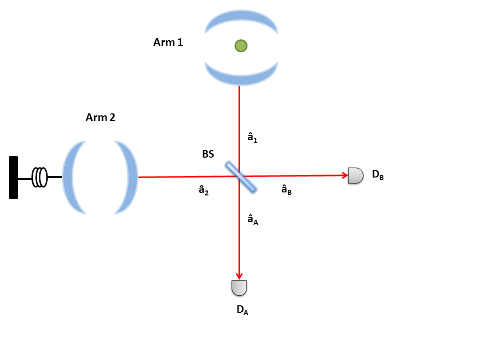
We consider, as shown in Fig. (1), an interferometer having two arms; a cavity containing a single (two-level) ion confined inside a Paul trap is positioned in arm 1 and an optomechanical cavity with a moving mirror is placed in arm 2. Firstly we are going to describe the preparation of the ionic and optomechanical systems, which consists in the independent preparation of an entangled state of the ion with the field in cavity 1, and the preparation of an entangled state involving the moving mirror with the field in cavity 2.
2.1 Trapped ion in a cavity
The Hamiltonian describing the dynamics of the quantized cavity field coupled to the ion (vibrational motion + internal electronic states) may be written as [3, 13]
| (1) |
where () denotes the annihilation (creation) operator of the cavity field (with frequency ), () is the annihilation (creation) operator of the vibrational degree of freedom of the center-of-mass of the ion (with frequency ), it is the atomic frequency, is the ion-field coupling constant, and is the Lamb-Dicke parameter; being the characteristic amplitude of the ion’s harmonic motion and is the wavelength of the cavity field. The Hamiltonian above may be linearized if the ion is confined in a region typically much smaller than the wavelength of light, or (Lamb-Dicke regime).
2.1.1 Trapped ion with quantum jumps: first red sideband case
An adequate way of treating the photon leaking process (from the cavities) is via the quantum jump formalism [19, 28, 29, 30]. The effective Hamiltonian of the cavity (having decay rate ) with a trapped ion governing the evolution while there is no photon detection, is given by
| (2) |
If we tune the system to the first red sideband (), we obtain, in the interaction picture,
| (3) |
Thus the associated non-Hermitian evolution operator is
| (4) |
We may choose the initial joint ion-cavity state as being
| (5) |
where e are the cavity field state (arm 1) and the vibrational ionic state, respectively, prepared in their vacuum states. We remark that in order to generate an entangled (ion + field) state, the ion’s electronic states must be prepared in a superposition of the “ground” state and the “excited” state [13], which could be done by applying convenient Raman pulses to the ion [2]. Nevertheless, it is required a simple preparation of both the ionic motion [2] and the cavity; they just need to be cooled down to their ground states.
The evolution of initial state in Eq.(5) under (4) followed by a suitable measurement of the ion’s electronic state results in (see Appendix A)
| (6) |
where is a normalizing constant. We may calculate the probability that there is no photodetection during the evolution, which alows the generation of the state in Eq.(6), or
| (7) | |||||
2.1.2 Trapped ion with quantum jumps: first blue sideband case
The ion-field detuning may also be adjusted to the first blue sideband, (), leading to the following interaction picture Hamiltonian (with quantum jump),
| (8) |
having the corresponding evolution operator
| (9) |
The cavity should be initially cooled to its vacuum state , but contrarily to the previous case (first red sideband), the ion should be initially prepared in its first excited state, or [2]. Thus
| (10) |
Following the same steps as in the red sideband case, we obtain (see Appendix A)
| (11) |
being a normalizing constant.
2.2 Optomechanical cavity
Now we turn our attention to arm 2, which contains the optomechanical cavity with a moving mirror. The Hamiltonian for such a system is given by [15]
| (12) |
Here , are the annihilation operator of the cavity field and the moving mirror (modeled as a simple harmonic oscillator), respectively, and is the moving mirror-cavity field coupling constant, , being the length of the cavity and the mirror’s mass.
2.2.1 Optomechanical cavity with quantum jumps
For an optomechanical cavity (decay rate ), the effective Hamiltonian in the quantum jump formalism will read
We assume the following specific initial state for the optomechanical system
| (15) |
where and are the initial cavity field (superposition) state and the initial (coherent) state of the moving mirror, respectively. Such an initial state could be prepared in the following way; the mirror should be first cooled down to its ground state [31, 32]. Then a coherent state of the oscillating mirror may be generated via the application of a light pulse (displacement) [1, 33]. The field of the corresponding cavity has to be prepared in a superposition of the vacuum state and the one-photon state, or . We find in the literature various proposals of generation of such cavity superposition states, for instance, using travelling atoms, as discussed in [34].
Thus the evolved optomechanical state vector will read
| (16) | |||||
with , , , and is a normalizing constant.
Now for , we obtain
| (17) |
which corresponds to the preparation of the optomechanical cavity prior to the detection stage.
3 Generation of hybrid entanglement between the ionic and optomechanical systems
In order to establish entanglement between the ion and the moving mirror subsystems, the fields from each cavity are combined in a beam-splitter [19, 29], as shown in Fig.(1). After impinging the beam splitter, photons may be detected by the photocounters or .
3.1 Ion-mirror entanglement: first red sideband case
Firstly we are going to consider the first red sideband preparation for the ionic system. If no photons are detected by (or ), the joint state in the beginning of the detection stage will be the product of state , the ionic-cavity field state (arm 1) in Eq.(6) and state , the mirror-cavity field (arm 2) in Eq.(17). Naturally it is required a synchronization of the actions during the process. We assume a finite detection time , and thus for the system’s joint state may be written as
| (18) |
where
| (19) | |||||
and
After the fields from each cavity cross the beam-splitter, if a photon is detected by , (field state projected onto ), we obtain
| (21) |
with
| (22) |
and
| (23) |
Now if a photon is detected by (field state projected onto ), the resulting state is
| (24) |
We have therefore demonstrated the possibility of generation of hybrid entangled states (Fock/coherent) in subsystems belonging to spatially separated cavities.
3.2 Ion-mirror entanglement: first blue sideband case
In what follows we discuss the first blue sideband case for the ionic system, with the optomechanical cavity having the same preparation as in the previous case [see Eq. (17)]. Analogously to the red sideband case, we obtain from Eq. (11)
| (25) | |||||
After the fields cross the beam-splitter, the subsequent detection of a photon by will result in the following state
| (26) |
where
| (27) |
and
| (28) |
If a photon is detected by , we obtain
| (29) |
Again, we have shown that entangled states of the hybrid type may be generated also for a different choice of frequency detunings.
4 Degree of Entanglement
An interesting peculiarity of the entangled states above is that, even if the mirror is initially just cooled down to its ground vibrational state (), the resulting states will be entangled. For instance,
| (30) |
for the red sideband case, and
| (31) |
for the blue sideband case. We also note that if , the generated states will be of the type
| (32) |
which are entangled states relevant for quantum computation purposes [35, 36, 37]. Now we would like to discuss the degree of entanglement, for instance, of the state generated in the red sideband case [Eq. (21)]. Firstly we define an orthogonal basis for the continuous variable sub-space (via Gram-Schmidt process) as
| (33) |
and
| (34) |
Where . We may rewrite the state in Eq. (21) in terms of the states above as
| (35) |
The negativity of the state above may be calculated via the usual definition [38]
| (36) |
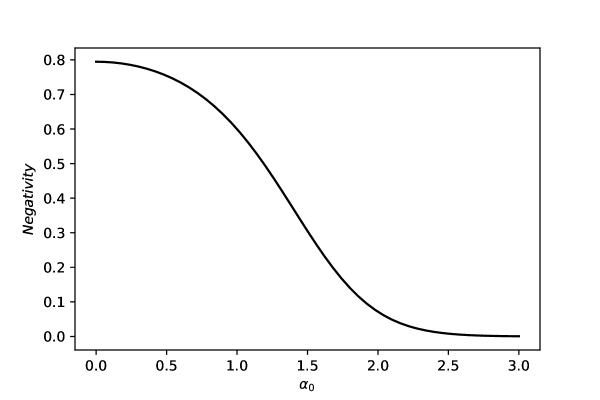
being the negative eigenvalues of the partial transpose of the density matrix associated to the state (35). In Fig. (2) we plot the negativity as a function of the coherent amplitude . In this specific case, for which , it is clear that the state has maximum entanglement for . As expected, for larger values of , the ion-mirror state becomes separable.
5 Discussion and conclusions
We have presented a scheme for entanglement generation between a moving mirror and a trapped ion assisted by the quantized fields of two cavities. As a first step, the mirror as well as the ion should independently couple to the fields of their own cavities. After an adequate preparation of the initial states, the corresponding outgoing cavity fields are combined in a beam-splitter. Then a subsequent photodetection would collapse the global state, making possible the generation of entangled states of the ion and mirror subsystems. Note that in order to accomplish the entangled state generation, one should wait (finite time) for a single click in either detector A or detector B.
Concerning the time scales involved, despite of the fact that the quantum sub-systems we are dealing with are of a very different nature, namely, a “microscopic” ion and a “macroscopic” mirror, both of them could in principle have equal (or very close) oscillating frequencies, e.g., in the MHz range [1, 2, 26]. We would like to remark that, due to the large mass difference between the ion and the mirror, a sort of “impedance mismatch” occurs in schemes in which the ion is directly coupled to the mirror [26]. Nevertheless, such a shortcoming is avoided in our light-mediated proposal, as the quantum sub-systems (ion/mirror) are indirectly coupled via the electromagnetic fields.
Yet, there are sources of decoherence caused by dephasing in the ionic system, mechanical damping in the mirror as well as cavity losses. The mechanical damping (mirror) and the dephasing (ion) rates are much smaller than the cavity damping rate, . Thus, in order to keep the integrity of the involved quantum states, we should have generation times much shorter than typical decoherence times, or and . Although those are experimentally challenging conditions, we are witnessing recent significant advances in both ionic and optomechanical systems, even approaching the single-photon strong coupling regime in optomechanical systems [1, 39, 40].
Finally, an important point is related to the verification of the existence of the generated entangled state. A direct measurement of the entangled state may not be an easy task in general. As an alternative, we may envisage an entanglement witness, which could be implemented via local measurements. After accomplishing the generation of the entangled state in Eq. (21), for instance, we could carry out the following procedure: i) perform a projective measurement [41] corresponding to on the ionic vibrational state, thus collapsing the mirror’s state to ; ii) displace the mirror (via a classical light pulse) by an amplitude , which would bring the mirror to its ground (vacuum) state; iii) measure the mirror state [33] in order to check whether it is (or not) in its vacuum state. This would allows us to discriminate the entangled state in Eq. (21) from the pure product state , for instance.
It should be emphasized that entanglement herein involves three important features of the resulting entangled states: states are related to massive, although different physical systems, viz., a trapped ion and a vibrating mirror; the entangled states are constituted by discrete states (ionic vibration) and continuous variable states (moving mirror), i.e., it is accomplished hybrid entanglement in spatially separated cavities; states involve a microscopic system (ion) and a macroscopic system (mirror), also referred as a micro-macro entangled state.
Acknowledgements
We would like to thank CNPq (Conselho Nacional para o Desenvolvimento Científico e Tecnológico) and FAPESP (Fundação de Amparo à Pesquisa do Estado de São Paulo), Brazil, for financial support through the National Institute for Science and Technology of Quantum Information (INCT-IQ under grant 2008/57856-6) and the Optics and Photonics Research Center (CePOF under grant 2005/51689-2).
Appendix A Generation of ion-field states
For the first red sideband case, the quantum jump evolution will be
which results in
Now if the ion’s electronic state is projected (via fluorescence, formally by applying ), we obtain
For , we have
Analogously, in the first blue sideband case the quantum jump evolution will lead to
| (37) | |||||
If the electronic state is projected on , and at the resulting cavity-ion state will now read
| (38) |
References
- [1] M. Aspelmeyer, T.J. Kippenberg and F. Marquardt, Rev. Mod. Phys. 86, 1391 (2014).
- [2] D. Leibfried, R. Blatt, C. Monroe and D. Wineland, Rev. Mod. Phys. 75, 281 (2003).
- [3] V. Bužek, G. Drobný, M.S. Kim, G. Adam and P.L. Knight, Phys. Rev. A 56, 2352 (1997).
- [4] A.B. Mundt, A. Kreuter, C. Russo, C. Becher, D. Leibfried, J.Eschner, F. Schmidt-Kaler and R. Blatt, Appl. Phys. B: Lasers Opt. 76, 117 (2003).
- [5] A. Stute, B. Casabone, P. Schindler, T. Monz, P.O. Schmidt, B. Brandstätter, T.E. Northup and R. Blatt, Nature 485, 482 (2012).
- [6] A. Stute, B. Casabone, B. Brandstätter, K. Friebe, T.E. Northup, and R. Blatt, Nature Photonics 7, 219 (2013).
- [7] J.I. Cirac and P. Zoller, Phys. Rev. Lett. 74, 4091 (1995).
- [8] F.L. Semião, A. Vidiella-Barranco and J.A. Roversi, Phys. Lett. A 299, 423 (1999).
- [9] D.M. Meekhof, C. Monroe, B.E. King, W.M. Itano, and D.J. Wineland, Phys. Rev. Lett. 76, 1796 (1996).
- [10] D. Leibfried, D.M. Meekhof, B.E. King, C. Monroe, W.M. Itano, and D.J. Wineland, Phys. Rev. Lett. 77, 4281 (1996).
- [11] A.F. Pace, M.J. Collett and D.F. Walls, Phys. Rev. A 47, 3173 (1993).
- [12] E. Verhagen, S. Deléglise, S. Weis, A. Schliesser and T.J. Kippenberg, Nature 482, 63 (2012).
- [13] F.L. Semião, A. Vidiella-Barranco and J.A. Roversi, Phys. Rev. A 64, 024305 (2001).
- [14] S. Mancini, V.I. Man’ko and P. Tombesi, Phys. Rev. A 55, 3042 (1997).
- [15] S. Bose, K. Jacobs and P.L. Knight, Phys. Rev. A 56, 4175 (1997).
- [16] S. Mancini, V. Giovannetti, D. Vitali and P. Tombesi, Phys. Rev. Lett. 88, 120401 (2002).
- [17] G. Vacanti, M. Paternostro, G.M. Palma and V. Vedral, New J. Phys. 10, 095014 (2008).
- [18] J.-Q. Liao, Q.-Q. Wu and F. Nori, Phys. Rev. A 89, 014302 (2014).
- [19] S. Bose, P.L. Knight, M.B. Plenio and V. Vedral, Phys. Rev. Lett. 83, 5158 (1999).
- [20] K. Kreis and P. van Loock, Phys. Rev. A 85, 032307 (2012).
- [21] X. Wang, J. Phys. A: Math. Gen. 34, 9577 (2001).
- [22] P. van Loock, T.D. Ladd, K. Sanaka, F. Yamaguchi, Kae Nemoto, W. J. Munro and Y. Yamamoto, Phys. Rev. Lett. 96, 240501 (2006).
- [23] Y.-B. Sheng, L. Zhou and G.-L. Long, Phys. Rev. A 88, 022302 (2013).
- [24] L. Tian, P. Zoller, Phys. Rev. Lett. 93, 266403 (2004).
- [25] W.K. Hensinger, D.W. Utami, H.-S. Goan, K. Schwab, C. Monroe and G.J. Milburn, Phys. Rev. A 72, 041405(R) (2005).
- [26] D. Hunger, S. Camerer, M. Korppi, A. Jöckel, T.W. Hänsch and P. Treutlein, C.R. Physique 12, 871 (2011).
- [27] K. Hammerer, M. Wallquist, C. Genes, M. Ludwig, F. Marquardt, P. Treutlein, P. Zoller, J. Ye and H.J. Kimble, Phys. Rev. Lett. 103, 063005 (2009).
- [28] M.B. Plenio and P.L. Knight, Rev. Mod. Phys. 70, 101 (1998).
- [29] D.E. Browne, M.B. Plenio, and S.F. Huelga, Phys. Rev. Lett. 91, 067901 (2003).
- [30] S.B. Zheng, Commun. Theor. Phys. 49, 925 (2008).
- [31] J.D. Teufel, T. Donner, Dale Li, J.W. Harlow, M.S. Allman, K. Cicak, A.J. Sirois, J.D. Whittaker, K.W. Lehnert and R.W. Simmonds, Nature 475, 389 (2011).
- [32] J. Chan, T.P. Mayer Alegre, A.H. Safavi-Naeini, J.T. Hill, A. Krause, S. Gröblacher, M. Aspelmeyer and O. Painter, Nature 478, 89 (2011).
- [33] M.R. Vanner, I. Pikovski, G.D. Cole, M.S. Kim, Č. Brukner, K. Hammerer, G.J. Milburn, and M. Aspelmeyer, PNAS 108, 16182 (2011).
- [34] P. Domokos, M. Brune, J.M. Raimond, and S. Haroche, Eur. Phys. J. D 1, 1 (1998).
- [35] T.P. Spiller, K. Nemoto, S.L. Braunstein, W.J. Munro, P. van Loock and G.J. Milburn, New J. Phys. 8, 30 (2006).
- [36] P. van Loock, Laser Photonics Rev. 5, 167 (2011).
- [37] H. Jeong, A. Zavatta, M. Kang, S.-W. Lee, L.S.Costanzo, S. Grandi,T. C.Ralph, and M. Bellini, Nature Photon. 8, 564 (2014).
- [38] G. Vidal and R.F. Werner, Phys. Rev. A 65, 032314 (2002).
- [39] S. Gröblacher1, K. Hammerer, M.R. Vanner, and M. Aspelmeyer, Nature 460, 724 (2009).
- [40] U. Akram, N. Kiesel, M. Aspelmeyer and G.J. Milburn, New J. Phys. 12, 083030 (2010).
- [41] M. Um, J. Zhang, D. Lv, Y. Lu, S. An, J.-N. Zhang, H. Nha, M. S. Kim, and K. Kim, Nat. Commun. 7, 11410 (2016).