language=C,captionpos=b,tabsize=3,frame=lines,keywordstyle=,morekeywords=or, then, s, End, c, cr, cn, cfr, cfn, xs, l, f, clear, bpull ,numbers=left,showtabs=false,morecomment=[l]–,
breaklines=true,stringstyle=,
basicstyle=
language=C,captionpos=b,tabsize=2,frame=lines,keywordstyle=,morekeywords=MODULE, VAR, ASSIGN, SPEC, init, next, case,esac,IVAR,self,INVARSPEC,st,rsu,numbers=left,showtabs=false,morecomment=[l]–,commentstyle=,
breaklines=true,stringstyle=,showstringspaces=false,
basicstyle=
language=C,captionpos=b,tabsize=3,frame=lines,keywordstyle=,morekeywords=SUB,REFINEMENT,COMPONENT,system,
CONNECTION,INPUT,PORT,OUTPUT,INTERFACE,assume,CONTRACT,
guarantee,always,REFINEDBY,numbers=left,showtabs=false,morecomment=[l]–,commentstyle=,
breaklines=true,stringstyle=,
basicstyle=
language=C,captionpos=b,tabsize=2,frame=lines,keywordstyle=,morekeywords=front,G,status,proving,tisp,st,cmd,L_CS,rsu,Act,rtF,cr,cn,cdr,cdn,Tprogress,t1,t2,numbers=left,showtabs=false,morecomment=[l]–,commentstyle=,
breaklines=true,stringstyle=,
basicstyle=
11institutetext: Université catholique de Louvain, Louvain-La-Neuve, Belgium
11email: {quentin.cappart—christophe.limbree—charles.pecheur}@uclouvain.be
22institutetext: Fondazione Bruno Kessler, Trento, Italy
22email: tonettas@fbk.eu
Verification of railway interlocking - Compositional approach with OCRA
Abstract
In the railway domain, an electronic interlocking is a computerised system that controls the railway signalling components (e.g. switches or signals) in order to allow a safe operation of the train traffic. Interlockings are controlled by a software logic that relies on a generic software and a set of application data particular to the station under control. The verification of the application data is time consuming and error prone as it is mostly performed by human testers.
In the first stage of our research [my_2], we built a model of a small Belgian railway station and we performed the verification of the application data with the nusmv model checker. However, the verification of larger stations fails due to the state space explosion problem. The intuition is that large stations can be split into smaller components that can be verified separately. This concept is known as compositional verification. This article explains how we used the ocra tool in order to model a medium size station and how we verified safety properties by mean of contracts. We also took advantage of new algorithms (k-liveness and ic3) recently implemented in nuxmv in order to verify LTL properties on our model.
1 Introduction
In the railway domain, an interlocking is a signalling subsystem that controls the routes, the switches and the signals before allowing a train through a station. Computer-based interlockings are configured based on a set of application data particular to each station. The safety of the train traffic relies on the correctness of the application data. Usually, the application data are prepared manually and are thus subject to human errors. For example, some prerequisites to the clearance (e.g. green light) of the origin signal of a route can be missing. This kind of error can easily be discovered by a code review or by testing on a simulator. However, errors caused by concurrent actions (e.g. route commands) are much harder to find. In this case, the combination of possible concurrent actions explodes quickly and testing all possible combinations manually is impracticable. The goal of our research is to develop a method based on model checking in order to verify the application data. Especially, our approach must scale-up and allow the verification of real size interlocking areas.
In a previous work [my_2], we built a model of a small Belgian railway station and we performed the verification of the application data with the nusmv model checker. However the verification of larger stations fails due to the state space explosion problem: the models are too big so that the model checker does not give a result in reasonable time. In this paper, we therefore tackle the problem with a compositional approach. The intuition is that large stations can be split into smaller components that can be verified separately. We report on the usage of the ocra tool in order to model a medium size station and on how we verified safety properties by mean of contracts. We also took advantage of new algorithms (k-liveness and ic3) recently implemented in nuxmv in order to verify LTL properties on our model.
Outline
The paper is structured as follows. In Section 2, we give a brief overview of the formal techniques that have been used in the case study. In the Section 3, we describe our model and the new features that we have added compared to our first model. In Section 4, we explain our verification strategy for larger stations. In Section 5, we discuss the performance of our verification approach and show how counter examples are produced when we insert errors in the application data. References to related work are provided in Section 7.
2 Contract Based Verification
2.1 Symbolic Model Checking
Model checking [Clarke1999] is a method to formally verify that a system is correct. In symbolic model checking [McM93], a system is described by a finite set of variables, the initial states are represented by a formula over , while the transitions by a formula over the variables and , where represent the value of after a transition. In the scope of this paper, we consider finite-state systems. Thus, without loss of generality, we can consider as Boolean variables and formulas in propositional logic.
A state is an assignment to the variables in . An initial state is a state that satisfies . A transition is a pair of states that satisfy . A path is a sequence of states such that is an initial state () and, for every , is a transition (). A state is reachable if there is a path such that for some .
In this paper, we specify transition systems in SMV [McM93], the input language of different model checkers such as nusmv [nusmv] and nuxmv [nuxmv]. Safety properties have been formalized by invariants, i.e. formulas over that must be satisfied by all reachable states. Temporal properties have been formalized into LTL [Pnu-FOCS77], which uses temporal operators to specify the temporal evolution of the transition system. The typical LTL formula we consider is in the form , where and are state formulas over . It means that whenever is true along an execution, is true in a state that follows along the trace.
2.2 nuXmv: Verification of Components with K-Liveness and IC3
In the case study we use nuxmv to prove invariants and LTL properties. In particular, we use the IC3 algorithm to prove invariants and the k-liveness algorithm for LTL properties.
IC3 [bradley] is a SAT-based algorithm for the verification of invariant properties of transition systems. Very briefly, the idea of IC3 is to build iteratively a sequence of formulas such that i) , ii) for all , is a set of clauses, iii) , iv) , and v) for all , where is the property that we want to verify. The formulas are therefore over-approximations of the state space reachable in up to transitions. They are iteratively strengthened and extended by generalizing clauses while disproving candidate counterexamples. The procedure terminates when either a counterexample is found or when for some so that is an inductive invariant that proves .
In [CGMT-TACAS14], IC3 has been integrated with predicate abstraction (PA) [GS97]. The approach leverages Implicit Abstraction (IA) [fm09], which allows to express abstract transitions without computing explicitly the abstract system, and is fully incremental with respect to the addition of new predicates.
k-liveness [kliveness] reduces liveness to a sequence of invariant checking. It uses a standard approach to reduce LTL verification for proving that a certain signal is eventually never visited (). The key insight of k-liveness is that, for finite-state systems, this is equivalent to find a such that is visited at most times, which in turn can be reduced to invariant checking. k-liveness is therefore a simple loop that increases at every iteration and calls a subroutine safe to check the invariant. In particular, the implementation in [kliveness] uses IC3 as safe and exploits the incrementality of IC3 to solve the sequence of invariant problems in an efficient way.
2.3 OCRA: Contract-Based Compositional Approach
In this paper, we adopt a compositional contract-based approach and we use the framework supported by the ocra tool [CDT-ASE13]. In particular, we specify component interfaces in terms of Boolean data ports and LTL contracts.
The ocra input language is a component-based description of the system architecture where every component is associated with one or more contracts. Each contract consists of an assumption and a guarantee specified as LTL formulas. The assumption represents a requirement on the environment of the component. The guarantee represents a requirements for the component implementation to be satisfied when the assumption holds.
When a component is decomposed into subcomponents, the contract refinement ensures that the guarantee of is not weakened by the contracts of the subcomponents while its assumption is not strengthened. This is checked independently from the actual implementation of the components and is verified by means of a set of proof obligations in LTL, which are discharged with model checking techniques [CT-SCP15].
ocra allows to associate to a component a behavioral model representing its implementation. The language used for the behavioral model is SMV. ocra checks if the SMV model is a correct implementation of the specified component simply calling NuSMV to verify if the SMV model satisfies the implication for every contract of the component.
3 System and Model Description
In this section, we describe the station, the model, and two new features of our model that are the directional locking and the sequential release.
3.1 The Station
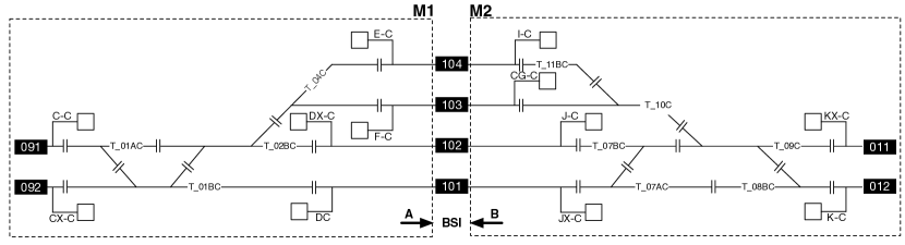
Braine l’Alleud station, shown in Fig. 1, is a medium size Belgian railway station comprising routes, switches, signals, and platforms (101-104). A platform is a section of pathway, alongside rail tracks at a railway station, metro station or tram stop, at which passengers may board. A route is a line of railway track between two signals on a rail system (e.g. route from signal CC to track 102 - signal JC). The station can be decomposed into two separate nearly symmetrical parts comprising routes each: and .
3.2 Composite System
The two parts of the station (i.e. and ) are not totally independent but have interfaces. These interfaces materialize a mutual exclusion mechanism preventing two trains to head for a platform in opposite direction at the same time (e.g. routes CC_101 and KC_101). Such routes are called conflicting routes. The exercise then consists in defining the system and its components, the interaction among the components, and try to prove some global properties on the system by making assumptions on the environment of each component.
The cuts (i.e. and ) are chosen so-that: 1) the number of interface variables is minimum, and 2) it sticks to the principle of distribution between interlockings applied in larger stations. The same principle will be applied to two interlockings sharing a section. As shown in Fig. 2, the system is made of three components: , , and . Partial Listing LABEL:lst:systRef shows how the components, and the interfaces are defined in ocra. The components: , , and are implemented in SMV language.
The components are defined by means of the keyword. The interfaces are defined as or (e.g. BSIB_101 is an output for and and an input for ). The and are connected by mean of the keyword.
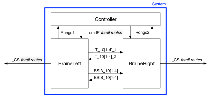
Figure 2 shows how the components are connected by interfaces. The L_CS OUTPUT variable (=TRUE) is an output of the system and states that the route is set and the origin signal at proceed aspect (e.g. the route is set and signal is green). The Controller outputs the cmdR variable stating that the controller has issued a route command. The Rongo{1,2} INPUT variable provides an acknowledgement that the route command has been properly processed by the interlocking. The two and interlocking components exchange the state of the platform track-circuits and the state of the BSI. A track-circuit is an electrical circuit that detects the presence of train in a block of track. The four track-circuits at the platform can be occupied by a train running in either , or . The BSI variable allows for mutual exclusion of conflicting routes leading to the same platform. The principle of functioning of the BSI is explained in Sect. 3.4.
3.3 and models
Figure 3 depicts the internal architecture of the M{1,2} component. Each component is implemented in an SMV model. All the modules represent a function achieved by the interlocking except for the train module. In fact the train module allows to simulate the interact of the interlocking with its environment.

The interlocking module is directly translated from the application data by mean of a translator tool described in [my_2] and models the routes and the locking logic of the switches. Upon a route request, the interlocking (1) verifies that the route can be set and then controls the track components accordingly. A proceed aspect (e.g. green) is sent to the origin signal of the route when the switches are locked in correct position and the track-circuits are clear (i.e. no other train is present on the route). Finally the interlocking detects the trains movement, releases the route and unlocks the resources used by the route. The track components (2) record the status of the track-side objects. For example: for a switch upon a command, the instance verifies that it is not locked before allowing the transition from one position to the other (e.g. left to right). The train modules (3) rely on the track layout of the station. When a signal is at proceed aspect, it simulates a train movement by actuation of the track components. This module is built independently of the application data by mean of a DSL (Domain Specific Language). The train module is local to M{1,2} as it is built based on the track layout of its component.
3.4 BSI Interface Explained
In order to prevent head to head train collisions, the interlocking use a locking mechanism (i.e. - Blocage du sens intermittent in French) that prevent two train to head for the same platform in opposite direction. Fig. 4 illustrates how the variables are actuated upon a route command.
For each platform, two locking variables are used (e.g. BSIA_102 and BSIB_102 for platform 2). When no route is set towards platform 102 , the two variables have a permissive value (Free). Upon a route command (e.g. ), the variable is set in a restrictive state (Locked). The routes in opposite direction (e.g. KC_102) are thereby blocked and the signal KC can never be commanded to a proceed aspect (e.g. green). The BSIA_102 variable regains its permissive value when the train has reached platform 102.
3.5 Sequential Release
When the interlocking grants access to a route, it locks all the resources that will be run through by the train: typically all the switches and the track-circuits. This prevents different routes that share those resources to be set at the same time. Such routes are called conflicting routes. Normally those resources are unlocked when the train has completely run through the route. They then become available for other routes. In large stations, it might be interesting to unlock the resources sequentially allowing them to be used by other routes before the train has totally run through. This contributes to improve the train traffic.
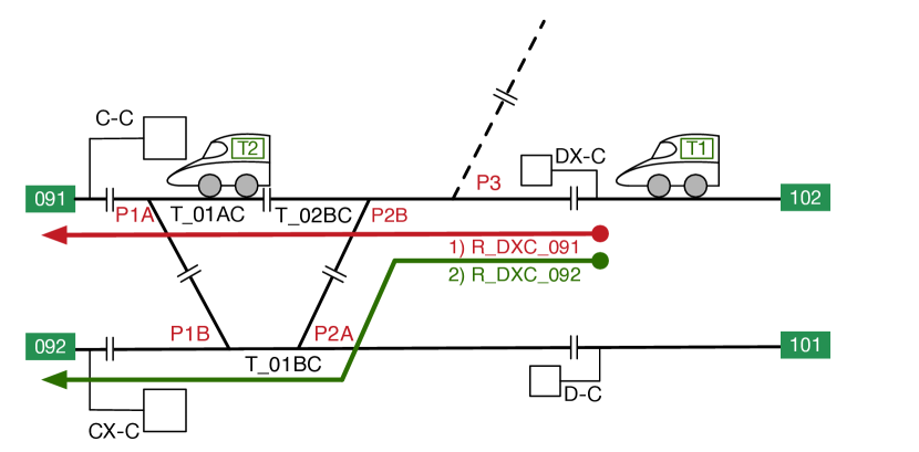
The principle of sequential release is illustrated in Fig. 5: the first route R_DXC_091 is set and prevents the second route R_DXC_092 to be set. The following switches are locked: P1A: left, P2B: right, and P3: right. According to the sequential release principle, the second route is set when the train is on the track-circuit T_01AC and when the track-circuit T_02BC is free.
4 Verification
The decomposition of one interlocking into several components allows to perform the verification on smaller models (one for each component) and thus limits the so-called state space explosion problem. Therefore we have used two different methods to verify the application data of Braine station: the first takes advantage of the ocra compositional verification tool and the second uses the nuxmv tool to verify local properties.
The compositional verification applies to the safety properties that imply an interaction between the two components. Those properties are expressed by mean of contracts. An example of contract is given in Listing LABEL:lst:cont1.
A second set of properties are verified straight on each component (i.e. and ) with nuxmv. Several instances of nuxmv can be started at the same time in order to reduce the computation time of the verification.
4.1 Compositional Verification
4.1.1 Conflicting Routes Controlled by Two Different Components
The routes R_CC_101 and R_KC_101 are conflicting because they share the same platform as a destination and the corresponding safety property is expressed by the formula: - in Listing LABEL:lst:cont1. Equation (4.1) shows how this property is verified by composition of the and modules. The first premise states that when the route R_CC_101 is set and origin signal is clear (i.e. R_CC_101_LCS is true), the mutual exclusion property (!BSIA_101 & BSIB_101) is true. The second premise states the same property () for the route R_KC_101. and are respectively CC_101_OK and KC_101_OK in Listing LABEL:lst:cont1. ocra performs the verification of these two properties with nuxmv. The third premise states that the first two premises entail the global property . Finally when all three premises are true, the composition of the components and verifies the global property .
In other words, if each component (i.e. and ) properly blocks the access to a shared platform when it controls a route, then the other component will not be able to control a conflicting route for the same platform.
Listing LABEL:lst:cont1 illustrates how the conflicting routes contract for the routes and is specified. First a top level contract (routesTowards_101) specifies that the two routes cannot be set at the same time. The top level contract is then refined by two contracts that apply on and : KC_101_OK and CC_101_OK respectively. These two contracts allow to verify that the and components handle the locking mechanism properly. The syntax of the language is given in ([OCRA_man]).
4.2 Local Safety Properties
The term Local Properties designates the properties that are not influenced by the environment of the component on which they are verified. Those properties are verified on each component SMV model with nuxmv. Due to the space limitation, those properties will not be explained in detail but examples are provided in Listing LABEL:lst:lProp. They are expressed in two different ways:
-
•
By mean of invariants (lines 1 to 5)
-
•
By mean of formulas and especially by using the ic3 algorithm (lines 6 and 7)
Explanation of the properties:
-
•
Line 1: the train never derails. A derailment happens when a train takes a trailing point in reverse direction.
-
•
Line 2: two trains never collide. This is done by verifying that their front never reaches the same track segment at the same time.
-
•
Line 3: a point never move when its home track-circuit is occupied.
-
•
Line 4: conflicting routes are not set at the same time. This formula verifies the same property as the contracts defined in ocra.
-
•
Line 5: the sub-routes are released in the correct sequence.
-
•
Line 6: a point never moves when its latching variable is in restrictive state. These formulas are checked by mean of k-liveness (see [klive1])
-
•
Line 7: signal replacement. The origin signal of a route is immediately commanded to red (replaced) when the train occupies the first track-circuit of the route and has triggered the first passage sensor. This prevents a second train to use the same authorization (i.e. signal green).
5 Results and Performance
In this section, we discuss the performance of our verification approach based on composition and local verification. We also illustrate how we validate the model and the properties by error seeding.
5.1 Performance
The tests were performed on 2.3 GHz i7 MacBookPro with 4 GB of RAM running under OS 10.11. Tables 1, 2, and 3 illustrate the results (in terms of computation time), which we achieve using different methods and different models. “BDD” refers to the fix-point algorithm using BDDs (see [Clarke1999]); “SAT(ic3)” refers to the ic3 algorithm using a SAT solver as backend (see [bradley]); “SMT(ic3)” refers to the ic3 algorithm integrated predicate abstraction using an SMT solver as back-end (see [CGMT-TACAS14]).
| Model | Tool | Method | Properties | Duration | |
|---|---|---|---|---|---|
| 1 | Monolithic model | NuSMV | BDD | Invariants | |
| 2 | Partial monolithic model | NuSMV | BDD | Invariants | |
| 3 | Monolithic model | NuXMV | SAT(ic3) | 10 Invariants | 123 sec |
| 4 | Monolithic model | NuXMV | SMT(ic3) | 10 Invariants | 80 sec |
Table 1 reports the performance of the verification of the application data for the station described in Section 3. Line 1 shows that nusmv could not terminate in one day. After reducing the size the state space by allowing only routes to be commanded, nusmv could build the reachable state space in days and verify invariants (line 2). One of the features of ocra is to allow to rebuild a monolithic ( routes) model based on the definition of the system. The verification of invariants is therefore possible. The results clearly show that ic3 with predicate abstraction performs better than plain ic3, and that both outperform the BDD-based algorithm on this case study.
| Model | Tool | Method | Properties | Duration | |
|---|---|---|---|---|---|
| 5 | Contract refinement | ocra | - | 4 Contracts | 7,34 sec |
| 6 | Implementation M1 | ocra | ic3 | 4 Contracts | 5,6 sec |
| 7 | Implementation M2 | ocra | ic3 | 4 Contracts | 14,94 sec |
| 8 | Composite monolithic | ocra | ic3 | 4 Contracts | 1242 sec |
Table 2 illustrates the performance of the verification of the contracts and their implementation. Line 5 corresponds to the verification of the premise 3 of Equation (4.1) (). Lines 6 and 7 are respectively related to the verification of the premisses 1 and 2 ( and ). The sum of the duration of these 3 tasks gives the time needed by ocra to check the coherence between the contracts and their implementation in the SMV models (i.e. 28 sec). This time is to be compared with the 1242 sec needed by ocra to verify the same contracts and implementations on a monolithic model.
| Model | Tool | Method | Properties | Duration | |
|---|---|---|---|---|---|
| 9 | M1 | NuXMV | BDD | 197 Invariants | 123 sec |
| 10 | M2 | NuXMV | BDD | 199 Invariants | 424 sec |
| 11 | M1 | NuXMV | SAT(ic3) | 12 LTL | 960 sec |
| 12 | M1 | NuXMV | SMT(ic3) | 12 LTL | 20 sec |
| 13 | M2 | NuXMV | SAT(ic3) | 12 LTL | 1036 sec |
| 14 | M2 | NuXMV | SMT(ic3) | 12 LTL | 740 sec |
Finally Table 3 illustrates the verification of the local safety properties on the and components. Two approaches are used: first some invariants are verified with nuxmv and the standard BDD and second 12 LTL properties are verified with the ic3 algorithm. An order file based on [WIN1] is used to optimize the BDD structure. ic3 with abstraction and the SMT MathSAT solver outperforms ic3 with MiniSAT in this context in an order of magnitude close to .
5.2 Error Seeding
In order to gain confidence in our model and properties, we have seeded errors in the model by removing some safety conditions in the route proving conditions111Conditions to give a proceed aspect on origin signal of the route.. As expected, ocra could not prove the safety property and produced a counterexample. Listing LABEL:lst:trace01 shows that the property is false (line 1) because the route R_KXC_101 is set (line 30) whereas the BSIB_101 is TRUE (line 5).
6 Related Work
Many works applied model checking to interlocking systems. One of the first work dates back to 1998 and is described in [Spin1]. However, as also concluded in [FMGF-FORMAT10], although small scale interlocking systems can be addressed by model checking, interlockings that control medium or large railway needs to tackle the state-space explosion problem. As shown also in [CCLNRRST-CAV12], a single approach is often not sufficient to prove all properties and sometimes a combination of approach may dramatically improve the performance.
Compositional approach is one method to reduce the complexity of the verification but is not the only one. For instance, Cappart et al. [cappart_simu] introduced a method based on discrete event simulations. The idea is to do not verify all the states but to limit the verification to a set of likely scenarios. However this method does not provide enough confidence that all the errors in the application data will be detected.
In [Winter1_1, Winter1], Winter shows how to compute optimized variable and transition orderings in order to speed-up the symbolic model checking of railway interlockings with NuSMV. She also reported on her findings on how to set the threshold for cluster.
In [WIN1], Winter et al. modelled the interlocking by means of the formal notation ASM that are more readable. The formal model is translated in NuSMV code and the Safety requirements are expressed in CTL.
In [IRSEProver], Peter Duggan (Siemens Rail Automation, UK) and Arne Borälv (Prover Technology AB, Sweden) have demonstrated that the Prover222http://www.prover.com tools were successfully used to generate and test the configuration data of a realistic size UK station.
In [LUX1], Haxthausen et al. detailed how they modelled an ETCS level 2 compatible Danish interlocking with the RT-Tester. The state space, the transition relation and the safety properties are efficiently evaluated by the SMT solvers that support bit vector and integer arithmetic. The model also include the sequential release feature.
In [RBCcompVerif], Xu et al. verifies hybrid safety properties of Automatic Collision Avoidance System (ACAS) in the European Train Control System (ETCS). They verify those properties using Compositional Verification rules based on weakly monotonic time extension.
In [SNCFpetri], Antoni et al. have developed a SIL4 interlocking that uses the Petri Nets as application data. In [rssrPetri], Dutilleul et al. have also used the Petri Nets in order to define a model pattern of railway interlocking.
7 Conclusions and Future Work
Conclusions
The verification of medium and large interlocking data is still a challenge due to the state space explosion problem affecting the model checking process. Our main contribution was to achieve the verification of the application data of a medium size railway interlocking by mean of compositional verification. In order to do that, we modelled our case study interlocking as a composite of smaller interlocking components in ocra and SMV language. The verification of the safety properties (expressed as contracts) was performed with ocra and nuxmv tools.
We have also added the sequential release functionality into our interlocking model. This functionality allows to increase the throughput of the railway network by releasing the route components earlier.
Finally, we have achieved the verification of LTL properties in efficient time thanks to the usage of the new ic3 algorithm implemented into nuxmv. The verification of the local components can be paralleled by running several instances of nuxmv at the same time.
Future work
In our future work, we will continue to refine the structure of the interlocking composite into adequate components (e.g. train). Our goal is to be able to verify safety properties on a network of interlockings by mean of compositional verification.
We will continue to develop the automatic translator tool in order to convert the application data of a network of interlockings into ocra language.
Another goal is to develop a model of an IL/ETCS installation in order to verify safety properties related to the train dynamic characteristics (i.e. speed and position). In order to do that we will extend our train module in order to make it continuous.